sensor DODGE CARAVAN 2008 5.G User Guide
[x] Cancel search | Manufacturer: DODGE, Model Year: 2008, Model line: CARAVAN, Model: DODGE CARAVAN 2008 5.GPages: 531, PDF Size: 7.72 MB
Page 177 of 531
WARNING!
Drivers must be careful when backing up even when
using the Rear Park Assist System. Always check
carefully behind your vehicle, and be sure to check
for pedestrians, animals, other vehicles, obstructions,
or blind spots before backing up. You are responsible
for the safety of your surroundings and must con-
tinue to pay attention while backing up. Failure to do
so can result in serious injury or death.
Before using the Rear Park Assist System, it is
strongly recommended that the ball mount and hitch
ball assembly be disconnected from the vehicle when
the vehicle is not used for towing. Failure to do so
can result in injury or damage to vehicles or obstacles
because the hitch ball will be much closer to the
obstacle than the rear fascia when the warning dis-
play turns the red LEDs on. Also, the sensors could
detect the ball mount and hitch ball assembly, de-
pending on its size and shape, giving a false indica-
tion that an obstacle is behind the vehicle.
CAUTION!
²To avoid vehicle damage the Rear Park Assist
System should only be used as a parking aid and
is unable to recognize every obstacle, including
small objects. Parking curbs might be temporarily
detected or not detected at all. Obstacles located
above or below the sensors will not be detected
when they are in close proximity to the rear of the
vehicle.
²To avoid vehicle damage the vehicle must be
driven slowly when using the Rear Park Assist
System to be able to stop in time when an obstacle
is detected. It is recommended that the driver look
over his/her shoulder when using the Rear Park
Assist System.
UNDERSTANDING THE FEATURES OF YOUR VEHICLE 175
3
Page 179 of 531
If(SERVICE PARK ASSIST SYSTEM(appears in the
Electronic Vehicle Information Center (EVIC), after mak-
ing sure the rear bumper is clean, please see your
authorized dealer.
Should this wrench symbol display with the
letterPnext to it, your Park Sense System
needs servicing. Contact your authorized
dealer.
Cleaning The Rear Park Assist System
Clean the Rear Park Assist Sensors with water, car wash
soap and a soft cloth. Do not use rough or hard cloths. Do
not scratch or poke the sensors, otherwise, you could
damage the sensors.
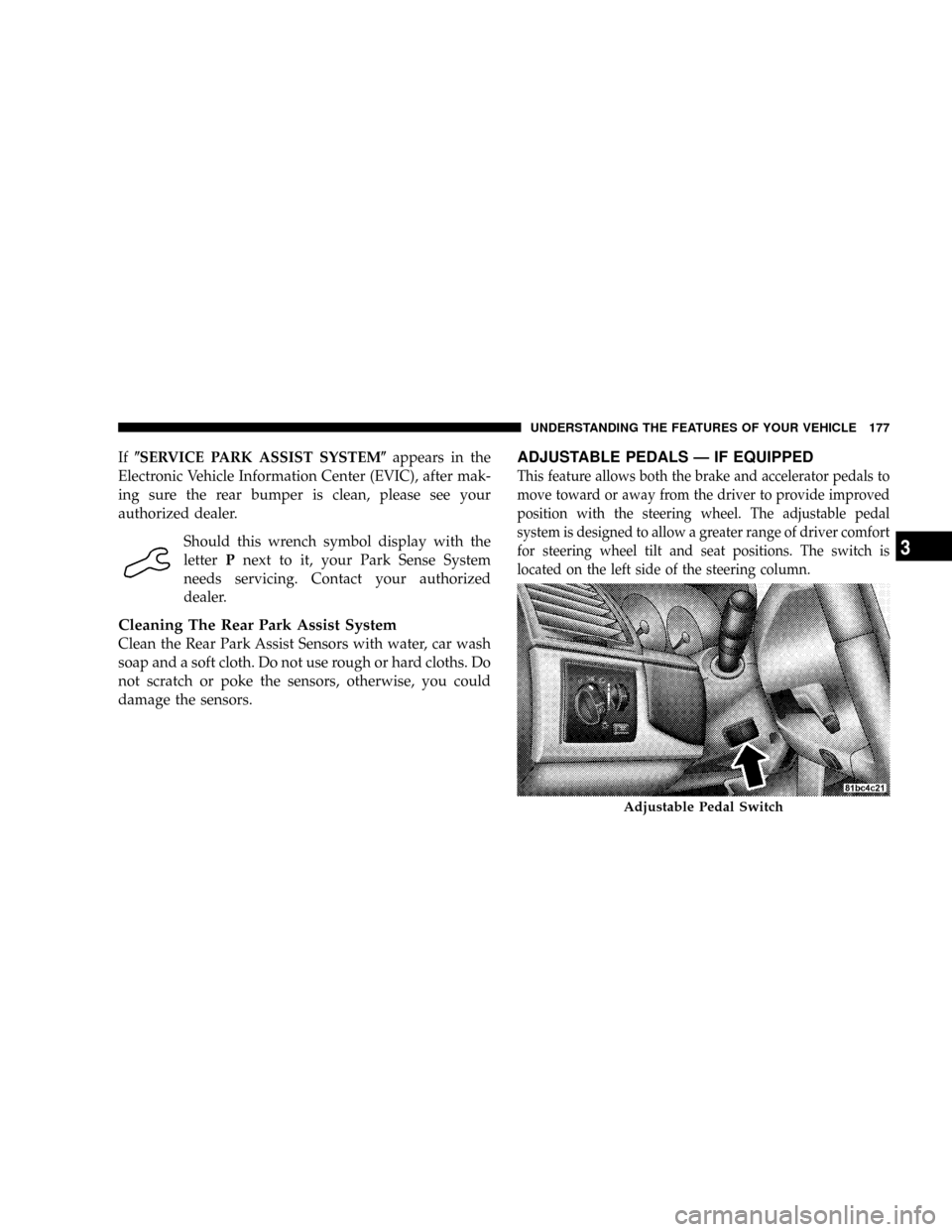
ADJUSTABLE PEDALS Ð IF EQUIPPED
This feature allows both the brake and accelerator pedals to
move toward or away from the driver to provide improved
position with the steering wheel. The adjustable pedal
system is designed to allow a greater range of driver comfort
for steering wheel tilt and seat positions. The switch is
located on the left side of the steering column.
Adjustable Pedal Switch
UNDERSTANDING THE FEATURES OF YOUR VEHICLE 177
3
Page 184 of 531
OVERHEAD CONSOLES
Front Overhead Console Ð If Equipped
Two versions of the overhead console are available. The
base front overhead console models feature fixed incan-
descent courtesy/reading lights, flip-down sunglass stor-
age and conversation mirror.
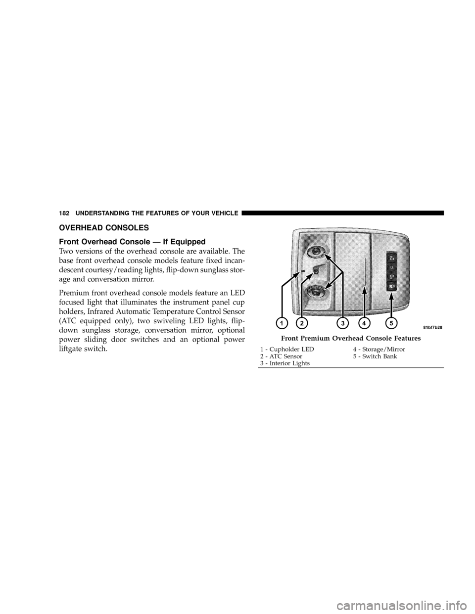
Premium front overhead console models feature an LED
focused light that illuminates the instrument panel cup
holders, Infrared Automatic Temperature Control Sensor
(ATC equipped only), two swiveling LED lights, flip-
down sunglass storage, conversation mirror, optional
power sliding door switches and an optional power
liftgate switch.
Front Premium Overhead Console Features
1 - Cupholder LED 4 - Storage/Mirror
2 - ATC Sensor 5 - Switch Bank
3 - Interior Lights 182 UNDERSTANDING THE FEATURES OF YOUR VEHICLE
Page 237 of 531
reduces fuel efficiency and tire tread life, and may affect
the vehicle's handling and stopping ability.
NOTE:Please note that the TPMS is not a substitute for
proper tire maintenance, and it is the driver 's responsi-
bility to maintain correct tire pressure, even if underin-
flation has not reached the level to trigger illumination of
the TPMS low tire pressure telltale.
Your vehicle has also been equipped with a TPMS
malfunction indicator to indicate when the system is not
operating properly. The TPMS malfunction indicator is
combined with the low tire pressure telltale. When the
system detects a malfunction, the telltale will flash for
approximately one minute and then remain continuously
illuminated. This sequence will continue upon subse-
quent vehicle start-ups as long as the malfunction exists.
When the malfunction indicator is illuminated, the sys-
tem may not be able to detect or signal low tire pressure
as intended. TPMS malfunctions may occur for a varietyof reasons, including the installation of replacement or
alternate tires or wheels on the vehicle that prevent the
TPMS from functioning properly.
NOTE:
Always check the TPMS malfunction telltale after
replacing one or more tires or wheels on your vehicle to
ensure that the replacement or alternate tires and wheels
allow the TPMS to continue to function properly.
CAUTION!
The TPMS has been optimized for the original
equipment tires and wheels. TPMS pressures and
warning have been established for the tire size
equipped on your vehicle. Undesirable system opera-
tion or sensor damage may result when using re-
placement equipment that is not of the same size,
type, and/or style. Aftermarket wheels can cause
sensor damage. Do not use aftermarket tire sealants
or balance beads if your vehicle is equipped with a
TPMS, as damage to the sensors may result.
UNDERSTANDING YOUR INSTRUMENT PANEL 235
4
Page 242 of 531
Compass/Temperature Display
Compass Variance
Compass Variance is the difference between magnetic
North and Geographic North. In some areas of the
country, the difference between magnetic and geographic
North is great enough to cause the compass to give false
readings. In order to ensure compass accuracy, the com-
pass variance should be properly set according to the
compass variance map zone that the vehicle is in.
NOTE:Magnetic materials should be kept away from
the top of the instrument panel. This is where the
compass sensor is located.
To Set the Variance
NOTE:Refer to the ªCompass Variance Mapº in the
following ªElectronic Vehicle Information Center
(EVIC)º section for your Zone Value.Start the engine, and leave the transmission gear selector
lever in the PARK position. Press and hold (approxi-
mately ten seconds) the CMTC reset button until the
current variance zone number is displayed. To change the
zone, press and release the CMTC reset button to incre-
ment the variance one step. Repeat as necessary, until the
desired variance is achieved.
NOTE:The factory default Zone is 8. During program-
ming, the zone value will wrap around from Zone 15 to
Zone 1.
Manual Compass Calibration
If the compass appears erratic, inaccurate or abnormal,
you may wish to calibrate the compass. Prior to calibrat-
ing the compass make sure the proper zone is selected.
1. Start the engine, and leave the transmission in the
PARK position.
240 UNDERSTANDING YOUR INSTRUMENT PANEL
Page 249 of 531
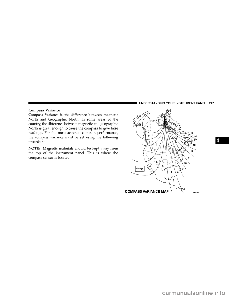
Compass Variance
Compass Variance is the difference between magnetic
North and Geographic North. In some areas of the
country, the difference between magnetic and geographic
North is great enough to cause the compass to give false
readings. For the most accurate compass performance,
the compass variance must be set using the following
procedure:
NOTE:Magnetic materials should be kept away from
the top of the instrument panel. This is where the
compass sensor is located.
UNDERSTANDING YOUR INSTRUMENT PANEL 247
4
Page 312 of 531
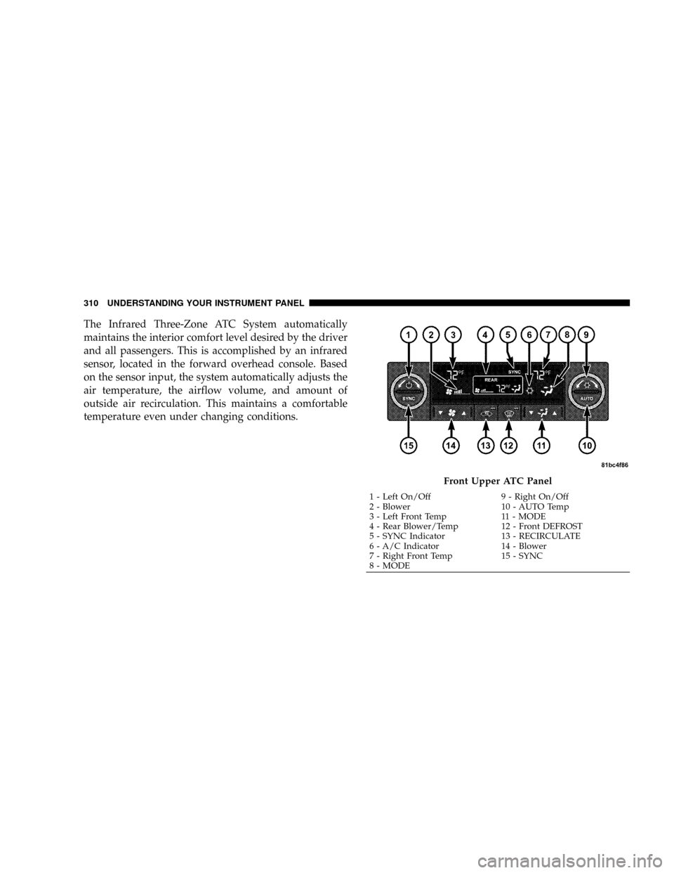
The Infrared Three-Zone ATC System automatically
maintains the interior comfort level desired by the driver
and all passengers. This is accomplished by an infrared
sensor, located in the forward overhead console. Based
on the sensor input, the system automatically adjusts the
air temperature, the airflow volume, and amount of
outside air recirculation. This maintains a comfortable
temperature even under changing conditions.
Front Upper ATC Panel
1 - Left On/Off 9 - Right On/Off
2 - Blower 10 - AUTO Temp
3 - Left Front Temp 11 - MODE
4 - Rear Blower/Temp 12 - Front DEFROST
5 - SYNC Indicator 13 - RECIRCULATE
6 - A/C Indicator 14 - Blower
7 - Right Front Temp 15 - SYNC
8 - MODE 310 UNDERSTANDING YOUR INSTRUMENT PANEL
Page 344 of 531
WARNING!
²BAS (Brake Assist System) cannot prevent the
natural laws of physics from acting on the vehicle,
nor can it increase the traction afforded by prevail-
ing road conditions.
²BAS cannot prevent accidents, including those
resulting from excessive speed in turns, driving on
very slippery surfaces, or hydroplaning. Only a
safe, attentive, and skillful driver can prevent
accidents.
²The capabilities of a BAS-equipped vehicle must
never be exploited in a reckless or dangerous
manner which could jeopardize the user's safety
or the safety of others.
Electronic Stability Program (ESP)
This system enhances directional control and stability of
the vehicle under various driving conditions. ESP cor-
rects for over/under steering of the vehicle by applying
the brake of the appropriate wheel to assist in counter-
acting the over/under steer condition. Engine power
may also be reduced to help the vehicle maintain the
desired path.
ESP uses sensors in the vehicle to determine the vehicle
path intended by the driver and compares it to the actual
path of the vehicle. When the actual path does not match
the intended path, ESP applies the brake of the appropri-
ate wheel to assist in counteracting the oversteer or
understeer condition.
²Oversteer - when the vehicle is turning more than
appropriate for the steering wheel position.
²Understeer - when the vehicle is turning less than
appropriate for the steering wheel position.
342 STARTING AND OPERATING
Page 372 of 531
increased to the recommended cold tire placard pressure
in order for the TPMS warning lamp to be turned off. The
system will automatically update and the TPMS warning
lamp will extinguish once the updated tire pressures
have been received. The vehicle may need to be driven
for up to 10 minutes above 15 mph (25 km/h) to receive
this information.
For example, your vehicle may have a recommended
cold (parked for more than three hours) tire pressure of
35 psi (241 kPa). If the ambient temperature is 68ÉF (20ÉC)
and the measured tire pressure is 30 psi (207 kPa), a
temperature drop to 20ÉF (-7ÉC) will decrease the tire
pressure to approximately 26 psi (179 kPa). This tire
pressure is sufficiently low enough to turn on the TPMS
Warning Light. Driving the vehicle may cause the tire
pressure to rise to approximately 30 psi (207 kPa), but the
TPMS Warning Light will still be on. In this situation, theTPMS Warning Light will turn off only after the tires
have been inflated to the vehicle's recommended cold tire
pressure value.
CAUTION!
The TPMS has been optimized for the original
equipment tires and wheels. TPMS pressures have
been established for the tire size equipped on your
vehicle. Undesirable system operation or sensor
damage may result when using replacement equip-
ment that is not of the same size, type, and/or style.
Aftermarket wheels can cause sensor damage. Do not
use aftermarket sealants or balance beads if your
vehicle is equipped with a TPMS, as damage to the
sensors may result.
370 STARTING AND OPERATING
Page 373 of 531
CAUTION!
After inspecting or adjusting the tire pressure always
reinstall the valve stem cap. This will prevent mois-
ture and dirt from entering the valve stem, which
could damage the TPMS SENSOR.
NOTE:
²The TPMS is not intended to replace normal tire care
and maintenance, or to provide warning of a tire
failure or condition.
²The TPMS should not be used as a tire pressure gauge
while adjusting your tire pressure.
²Driving on a significantly under-inflated tire causes
the tire to overheat and can lead to tire failure.
Under-inflation also reduces fuel efficiency and tire
tread life, and may affect the vehicle's handling and
stopping ability.
²The TPMS is not a substitute for proper tire mainte-
nance, and it is the driver's responsibility to maintain
correct tire pressure, using an accurate tire pressure
gage, even if under-inflation has not reached the level
to trigger illumination of the TPMS Warning Lamp.
NOTE:Seasonal temperature changes will affect tire
pressure, and the TPMS will monitor the actual tire
pressure in the tire.
BASIC TPMS WITHOUT EVIC Ð IF EQUIPPED
The TPMS uses wireless technology with wheel rim
mounted electronic sensors to monitor tire pressure lev-
els. Sensors, mounted to each wheel as part of the valve
stem, transmit tire pressure readings to the Receiver
Module.
NOTE:It is particularly important, for you to check the
tire pressure in all of your tires regularly and to maintain
the proper pressure.
STARTING AND OPERATING 371
5