engine DODGE CARAVAN 2010 Owner's Manual
[x] Cancel search | Manufacturer: DODGE, Model Year: 2010, Model line: CARAVAN, Model: DODGE CARAVAN 2010Pages: 530, PDF Size: 9.59 MB
Page 156 of 530
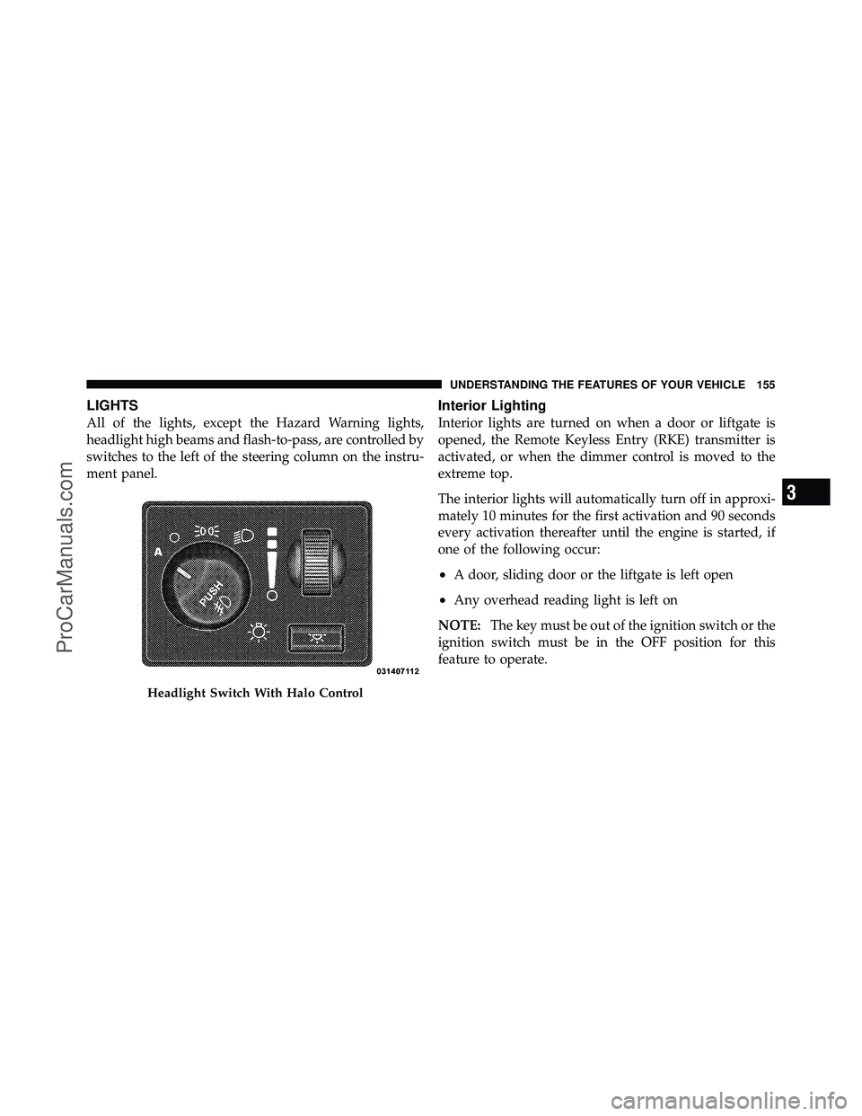
LIGHTS
All of the lights, except the Hazard Warning lights,
headlight high beams and flash-to-pass, are controlled by
switches to the left of the steering column on the instru-
ment panel.
Interior Lighting
Interior lights are turned on when a door or liftgate is
opened, the Remote Keyless Entry (RKE) transmitter is
activated, or when the dimmer control is moved to the
extreme top.
The interior lights will automatically turn off in approxi-
mately 10 minutes for the first activation and 90 seconds
every activation thereafter until the engine is started, if
one of the following occur:
•A door, sliding door or the liftgate is left open
•Any overhead reading light is left on
NOTE: The key must be out of the ignition switch or the
ignition switch must be in the OFF position for this
feature to operate.
Headlight Switch With Halo Control
3
UNDERSTANDING THE FEATURES OF YOUR VEHICLE 155
ProCarManuals.com
Page 159 of 530
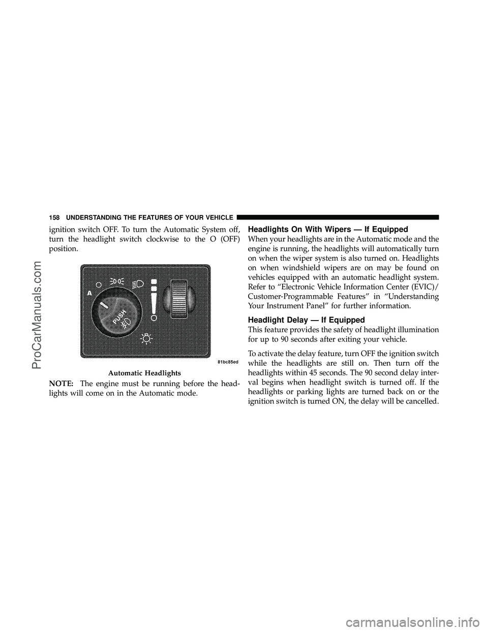
ignition switch OFF. To turn the Automatic System off,
turn the headlight switch clockwise to the O (OFF)
position.
NOTE:The engine must be running before the head-
lights will come on in the Automatic mode.Headlights On With Wipers — If Equipped
When your headlights are in the Automatic mode and the
engine is running, the headlights will automatically turn
on when the wiper system is also turned on. Headlights
on when windshield wipers are on may be found on
vehicles equipped with an automatic headlight system.
Refer to “Electronic Vehicle Information Center (EVIC)/
Customer-Programmable Features” in “Understanding
Your Instrument Panel” for further information.
Headlight Delay — If Equipped
This feature provides the safety of headlight illumination
for up to 90 seconds after exiting your vehicle.
To activate the delay feature, turn OFF the ignition switch
while the headlights are still on. Then turn off the
headlights within 45 seconds. The 90 second delay inter-
val begins when headlight switch is turned off. If the
headlights or parking lights are turned back on or the
ignition switch is turned ON, the delay will be cancelled.
Automatic Headlights
158 UNDERSTANDING THE FEATURES OF YOUR VEHICLE
ProCarManuals.com
Page 160 of 530
When exiting the vehicle the driver can choose to have
the headlights remain on for 30, 60 or 90 seconds or not
remain on. To change the timer setting, see your autho-
rized dealer.
The headlight delay time is programmable on vehicles
equipped with an EVIC. Refer to “Electronic Vehicle
Information Center (EVIC)/Customer-Programmable
Features” in “Understanding Your Instrument Panel” for
further information.
If the headlights are turned off before the ignition, they
will turn off in the normal manner.
NOTE:The headlights must be turned off within 45 sec-
onds of turning the ignition OFF to activate this feature.Lights-On Reminder
If the headlights or the parking lights are left on, or if the
dimmer control is in the extreme top position after the
ignition switch is turned OFF, a chime will sound when
the driver’s door is opened.
Daytime Running Lights — If Equipped
The headlights on your vehicle will illuminate when the
engine is started and the transmission is in any gear
except PARK. This provides a constant lights on condi-
tion until the ignition is turned OFF. The lights illuminate
at less than 50% of normal intensity. If the parking brake
is applied, the Daytime Running Lights (DRL) will turn
off. Also, if a turn signal is activated, the DRL lamp on the
same side of the vehicle will turn off for the duration of
the turn signal activation. Once the turn signal is no
longer active, the DRL lamp will illuminate.
3
UNDERSTANDING THE FEATURES OF YOUR VEHICLE 159
ProCarManuals.com
Page 197 of 530
connected to the battery. Do not exceed a maximum
power of 160 Watts (13 Amps) shared between the lower
panel outlet and the removable floor console outlet.
The outlet in the rear quarter panel near the liftgate and
the upper outlet in the instrument panel are both con-
trolled by the ignition switch. Each of these outlets can
support 160 Watts (13 Amps). Do not exceed 160 Watts
(13 Amps) for each of these outlets.
The power outlets include tethered caps, labeled with a
key or battery symbol indicating the power source. The
power outlet, located on the lower instrument panel, is
powered directly from the battery. Items plugged into
this power outlet may discharge the battery and/or
prevent the engine from starting.
WARNING!
To avoid serious injury or death:(Continued)
WARNING! (Continued)
•Only devices designed for use in this type of
outlet should be inserted into any 12 Volt outlet.
•Do not touch with wet hands.
•Close the lid when not in use and while driving
the vehicle.
•If this outlet is mishandled, it may cause an
electric shock and failure.
CAUTION!
•Many accessories that can be plugged in draw
power from the vehicle’s battery, even when not in
use (i.e., cellular phones, etc.). Eventually, if
plugged in long enough, the vehicle’s battery will
discharge sufficiently to degrade battery life
and/or prevent the engine from starting.(Continued)
196 UNDERSTANDING THE FEATURES OF YOUR VEHICLE
ProCarManuals.com
Page 214 of 530
3. Pull rearward to disengage from floor and remove
console.
To reinstall the console:
1. Position the console at a slight angle (rear slightly
higher than the front).
2. Slide the console forward into the floor bracket.
3. Rotate the rear of the console down until it is resting
on the floor bracket.
4. Push down on the rear of the console until it is seated
in the rear floor bracket.
5. Pull up on the console to be sure it is firmly latched.
WARNING!
In an accident, serious injury could result if the remov-
able floor console is not properly installed. Always be
sure the removable floor console is fully latched.
REAR WINDOW FEATURES
Rear Window Defroster
The rear window defroster button is located on the
climate control (Mode) knob. Press this button to
turn on the rear window defroster and the heated outside
mirrors (if equipped). An indicator in the button will
illuminate when the rear window defroster is on. The
rear window defroster automatically turns off after ap-
proximately 10 minutes. For an additional five minutes of
operation, press the button a second time.
NOTE:
•You can turn off the heated mirror feature at anytime
by pressing the rear window defroster switch a second
time.
•To prevent excessive battery drain, use the rear win-
dow defroster only when the engine is operating.
3
UNDERSTANDING THE FEATURES OF YOUR VEHICLE 213
ProCarManuals.com
Page 228 of 530
INSTRUMENT CLUSTER DESCRIPTIONS
1. Fuel Gauge
The pointer shows the level of fuel in the fuel tank when
the ignition switch is in the ON position.
2. Fuel Door ReminderThe arrow in this symbol is a reminder that the
Fuel Filler Door is located on the left side of the
vehicle.
3. Temperature Gauge
The temperature gauge shows engine coolant tempera-
ture. Any reading within the normal range indicates that
the engine cooling system is operating satisfactorily. The gauge pointer will likely indicate a higher tempera-
ture when driving in hot weather, up mountain grades,
or when towing a trailer. It should not be allowed to
exceed the upper limits of the normal operating range.
CAUTION!
Driving with a hot engine cooling system could
damage your vehicle. If temperature gauge reads
“H“, pull over and stop the vehicle. Idle the vehicle
with the air conditioner turned off until the pointer
drops back into the normal range. If the pointer
remains on the “H”, and you hear continuous chimes,
turn the engine off immediately, and call an autho-
rized dealer for service.4
UNDERSTANDING YOUR INSTRUMENT PANEL 227
ProCarManuals.com
Page 229 of 530
WARNING!
A hot engine cooling system is dangerous. You or
others could be badly burned by steam or boiling
coolant. You may want to call an authorized dealer if
your vehicle overheats. If you decide to look under
the hood yourself, see “Maintaining Your Vehicle”.
Follow the warnings under the Cooling System Pres-
sure Cap paragraph.
4. Speedometer
Indicates vehicle speed.
5. Turn Signal Indicators The arrow will flash with the exterior turn signal
when the turn signal lever is operated.
If the vehicle electronics sense that the vehicle has
traveled about 1 mile (1.6 km) with the turn signals on, a continuous chime will sound to alert you to turn the
signals off. If either indicator flashes at a rapid rate, check
for a defective outside light bulb.
6. High Beam Indicator
This indicator shows that the high beam head-
lights are on. Push the multifunction lever forward
to switch the headlights to high beam and pull toward
yourself (normal position) to return to low beam.
7. Anti-Lock Brake (ABS) Light This light monitors the Anti-Lock Brake System
(ABS). The light will turn on when the ignition
switch is turned to the ON position and may
stay on for as long as four seconds.
If the ABS light remains on or turns on while driving, it
indicates that the Anti-Lock portion of the brake system
is not functioning and that service is required. However,
the conventional brake system will continue to operate
normally if the BRAKE warning light is not on.
228 UNDERSTANDING YOUR INSTRUMENT PANEL
ProCarManuals.com
Page 231 of 530
WARNING!
Driving a vehicle with the red brake light on is
dangerous. Part of the brake system may have failed.
It will take longer to stop the vehicle. You could have
an accident. Have the vehicle checked immediately.
Vehicles equipped with the Anti-Lock Brake System
(ABS), are also equipped with Electronic Brake Force
Distribution (EBD). In the event of an EBD failure, the
Brake Warning Light will turn on along with the ABS
Light. Immediate repair to the ABS system is required.
Operation of the Brake Warning Light can be checked by
turning the ignition switch from the OFF position to the
ON position. The light should illuminate for approxi-
mately two seconds. The light should then turn off unless
the parking brake is applied or a brake fault is detected.
If the light does not illuminate, have the light inspected
by an authorized dealer. The light also will turn on when the parking brake is
applied with the ignition switch in the ON position.
NOTE:
This light shows only that the parking brake is
applied. It does not show the degree of brake application.
9. Tachometer — Premium Instrument Cluster Only
The white area of the scale shows the permissible engine
revolutions-per-minute (RPM x 1000) for each gear range.
Before reaching the red area, ease up on the accelerator to
prevent engine damage.
10. Shift Lever Indicator
The Shift Lever Indicator is self-contained within the
instrument cluster. It displays the gear position of the
automatic transmission.
NOTE: You must apply the brakes before shifting from
PARK.
230 UNDERSTANDING YOUR INSTRUMENT PANEL
ProCarManuals.com
Page 234 of 530
damaged, a “noFUSE” message will display in the odom-
eter display area. For further information on fuses and
fuse locations refer to “Fuses” in “Maintaining Your
Vehicle”.
CHAngE OIL
Your vehicle is equipped with an engine oil change
indicator system. The “Change Oil” message will flash in
the instrument cluster odometer for approximately
12 seconds after a single chime has sounded to indicate
the next scheduled oil change interval. The engine oil
change indicator system is duty cycle-based, which
means the engine oil change interval may fluctuate
dependent upon your personal driving style.
Unless reset, this message will continue to display each
time you turn the ignition switch to the ON/RUN
position. To turn off the message temporarily, press and
release the Trip Odometer button on the instrumentcluster. To reset the oil change indicator system (after
performing the scheduled maintenance), refer to the
following procedure:
1. Turn the ignition switch to the ON position (Do not
start the engine).
2. Fully depress the accelerator pedal slowly three times
within 10 seconds.
3. Turn the ignition switch to the OFF/LOCK position.
NOTE:
If the indicator message illuminates when you
start the vehicle, the oil change indicator system did not
reset. If necessary repeat this procedure.
13. Odometer / Trip Odometer Display Reset Button
To reset a message display (gATE, gASCAP, noFUSE,
CHAngE OIL, LoCOOL, LoWASH), push and hold the
button until the display resets (approximately two sec-
onds).
4
UNDERSTANDING YOUR INSTRUMENT PANEL 233
ProCarManuals.com
Page 235 of 530
14. Electronic Stability Program (ESP) Indicator
Light / Traction Control System (TCS) Indicator LightIf this indicator light flashes during accelera-
tion, apply as little throttle as possible. While
driving, ease up on the accelerator. Adapt your
speed and driving to the prevailing road con-
ditions, and do not switch off the Electronic Stability
Program (ESP), or Traction Control System (TCS).
15. Malfunction Indicator Light (MIL) The Malfunction Indicator Light (MIL) is part of
an onboard diagnostic system called OBD that
monitors engine and automatic transmission con-
trol systems. The light will illuminate when the key is in
the ON position before engine start. If the bulb does not
come on when turning the key from OFF to ON, have the
condition checked promptly. Certain conditions such as a loose or missing gas cap,
poor fuel quality, etc., may illuminate the MIL after
engine start. The vehicle should be serviced if the light
stays on through several of your typical driving cycles. In
most situations, the vehicle will drive normally and will
not require towing.
CAUTION!
Prolonged driving with the MIL on could cause
damage to the engine control system. It also could
affect fuel economy and drivability. If the MIL is
flashing, severe catalytic converter damage and
power loss will soon occur. Immediate service is
required.
234 UNDERSTANDING YOUR INSTRUMENT PANEL
ProCarManuals.com