jump start DODGE CHALLENGER 2013 3.G User Guide
[x] Cancel search | Manufacturer: DODGE, Model Year: 2013, Model line: CHALLENGER, Model: DODGE CHALLENGER 2013 3.GPages: 140, PDF Size: 5.35 MB
Page 3 of 140
INTRODUCTION/WELCOME
WELCOME FROM CHRYSLER GROUP LLC . . . 2
CONTROLS AT A GLANCE
DRIVER COCKPIT................4
INSTRUMENT CLUSTER.............6
GETTING STARTED
KEYFOB .....................8
REMOTE START.................9
KEYLESS ENTER-N-GO™............9
THEFT ALARM.................13
SEATBELT ...................13
SUPPLEMENTAL RESTRAINT SYSTEM
(SRS)—AIRBAGS ................14
CHILD RESTRAINTS..............15
FRONT SEATS.................18
REARSEAT ...................20
HEATEDSEATS ................20
TILT/TELESCOPING STEERING COLUMN . . . 21
OPERATING YOUR VEHICLE
ENGINE BREAK-IN RECOMMENDATIONS . . . 22
TURN SIGNAL/WIPER/WASHER/HIGH
BEAM LEVER..................23
HEADLIGHT SWITCH..............24
SPEED CONTROL................25
AUTOSTICK®..................26
SPORT MODE – IF EQUIPPED..........27
MANUAL TRANSMISSION 1 TO 4 SKIP SHIFT . . 27MANUAL CLIMATE CONTROLS........28
AUTOMATIC TEMPERATURE
CONTROLS (ATC)...............29
POWER SUNROOF...............30
WIND BUFFETING...............31
ELECTRONICS
YOUR VEHICLE'S SOUND SYSTEM......32
Uconnect® 130.................34
Uconnect® 130 WITH SiriusXM
SATELLITE RADIO...............36
Uconnect® 430/430N.............38
Uconnect® 730N................47
SiriusXM SATELLITE RADIO/TRAVEL LINK . . 57
STEERING WHEEL AUDIO CONTROLS....60
Uconnect® Phone...............60
Uconnect® VOICE COMMAND.........63
Bluetooth® STREAMING AUDIO........66
iPod®/USB/MP3 CONTROL..........66
ELECTRONIC VEHICLE INFORMATION
CENTER (EVIC).................67
PROGRAMMABLE FEATURES.........68
UNIVERSAL GARAGE DOOR OPENER
(HomeLink®)..................69
POWER OUTLETS...............72
UTILITY
TRAILER TOWING WEIGHTS
(MAXIMUM TRAILER WEIGHT RATINGS) . . . 73
RECREATIONAL TOWING
(BEHIND MOTORHOME, ETC.).........73
SRT8
AUTOSTICK®..................74ELECTRONIC CONTROL DAMPING SYSTEM . . 75PERFORMANCE FEATURES..........76
SUMMER/THREE-SEASON TIRES.......77
WHAT TO DO IN EMERGENCIES
ROADSIDE ASSISTANCE............78INSTRUMENT CLUSTER WARNING LIGHTS . . 78IF YOUR ENGINE OVERHEATS.........83
JACKING AND TIRE CHANGING........84
BATTERY LOCATION..............90
TIREFIT KIT..................90
JUMP-STARTING...............96
SHIFT LEVER OVERRIDE...........98
TOWING A DISABLED VEHICLE........99
FREEING A STUCK VEHICLE.........100
EVENT DATA RECORDER (EDR)........101
MAINTAINING YOUR VEHICLE
OPENING THE HOOD.............102
ENGINE COMPARTMENT...........103
FLUIDS AND CAPACITIES - NON SRT8....106
MAINTENANCE SCHEDULE..........110
FUSES.....................118
TIRE PRESSURES...............121
WHEEL AND WHEEL TRIM CARE......122
EXTERIOR BULBS..............122
CONSUMER ASSISTANCE
CHRYSLER GROUP LLC
CUSTOMER CENTER.............123
CHRYSLER CANADA INC.
CUSTOMER CENTER.............123
ASSISTANCE FOR THE HEARING
IMPAIRED ...................123
PUBLICATIONS ORDERING..........123
REPORTING SAFETY DEFECTS IN THE
UNITEDSTATES ................124
MOPAR ACCESSORIES
AUTHENTIC ACCESSORIES BY MOPAR® . . 125
INDEX....................126
FAQ (How To?)
FREQUENTLY ASKED QUESTIONS......129
TABLE OF CONTENTS
Page 10 of 140
KEY FOB
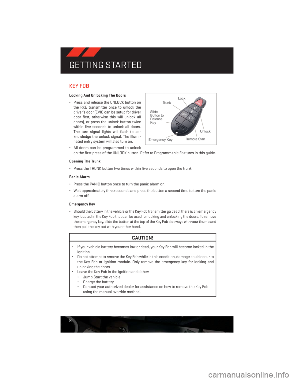
Locking And Unlocking The Doors
• Press and release the UNLOCK button on
the RKE transmitter once to unlock the
driver’s door (EVIC can be setup for driver
door first, otherwise this will unlock all
doors), or press the unlock button twice
within five seconds to unlock all doors.
The turn signal lights will flash to ac-
knowledge the unlock signal. The illumi-
nated entry system will also turn on.
• All doors can be programmed to unlock
on the first press of the UNLOCK button. Refer to Programmable Features in this guide.
Opening The Trunk
• Press the TRUNK button two times within five seconds to open the trunk.
Panic Alarm
• Press the PANIC button once to turn the panic alarm on.
• Wait approximately three seconds and press the button a second time to turn the panic
alarm off.
Emergency Key
•
Should the battery in the vehicle or the Key Fob transmitter go dead, there is an emergency
key located in the Key Fob that can be used for locking and unlocking the doors. To remove
the emergency key, slide the button at the top of the Key Fob sideways with your thumb and
then pull the key out with your other hand.
CAUTION!
• If your vehicle battery becomes low or dead, your Key Fob will become locked in the
ignition.
• Do not attempt to remove the Key Fob while in this condition, damage could occur to
the Key Fob or ignition module. Only remove the emergency key for locking and
unlocking the doors.
• Leave the Key Fob in the ignition and either:
• Jump Start the vehicle.
• Charge the battery.
• Contact your authorized dealer for assistance on how to remove the Key Fob
using the manual override method.
GETTING STARTED
8
Page 92 of 140
BATTERY LOCATION
• The battery is stored under an access cover in the trunk. Remote battery posts are
located on the right side of the engine compartment for jump-starting.
TIREFIT KIT
• Small punctures up to 1/4 in (6 mm) in the tire tread can be sealed with TIREFIT. Foreign
objects (e.g., screws or nails) should not be removed from the tire. TIREFIT can be used in
outside temperatures down to approximately -4°F (-20°C).
• This kit will provide a temporary tire seal, allowing you to drive your vehicle up to
100 miles (160 km) with a maximum speed of 55 mph (88 km/h).
TIREFIT Storage
• The TIREFIT kit is located in the trunk.
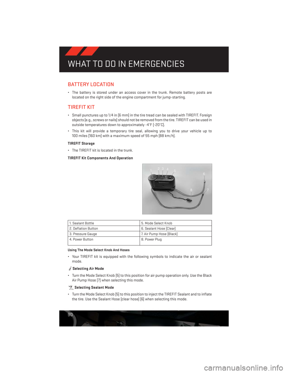
TIREFIT Kit Components And Operation
1. Sealant Bottle 5. Mode Select Knob
2. Deflation Button 6. Sealant Hose (Clear)
3. Pressure Gauge 7. Air Pump Hose (Black)
4. Power Button 8. Power Plug
Using The Mode Select Knob And Hoses
• Your TIREFIT kit is equipped with the following symbols to indicate the air or sealant
mode.
Selecting Air Mode
• Turn the Mode Select Knob (5) to this position for air pump operation only. Use the Black
Air Pump Hose (7) when selecting this mode.
Selecting Sealant Mode
• Turn the Mode Select Knob (5) to this position to inject the TIREFIT Sealant and to inflate
the tire. Use the Sealant Hose (clear hose) (6) when selecting this mode.
WHAT TO DO IN EMERGENCIES
90
Page 98 of 140
JUMP-STARTING
• If your vehicle has a discharged battery it
can be jumpstarted using a set of jumper
cables and a battery in another vehicle or
by using a portable battery booster pack.
• Jump-starting can be dangerous if done
improperly so please follow the proce-
dures in this section carefully.
NOTE:
When using a portable battery booster pack
follow the manufacturer’s operating instruc-
tions and precautions.
Preparations for Jump-Start
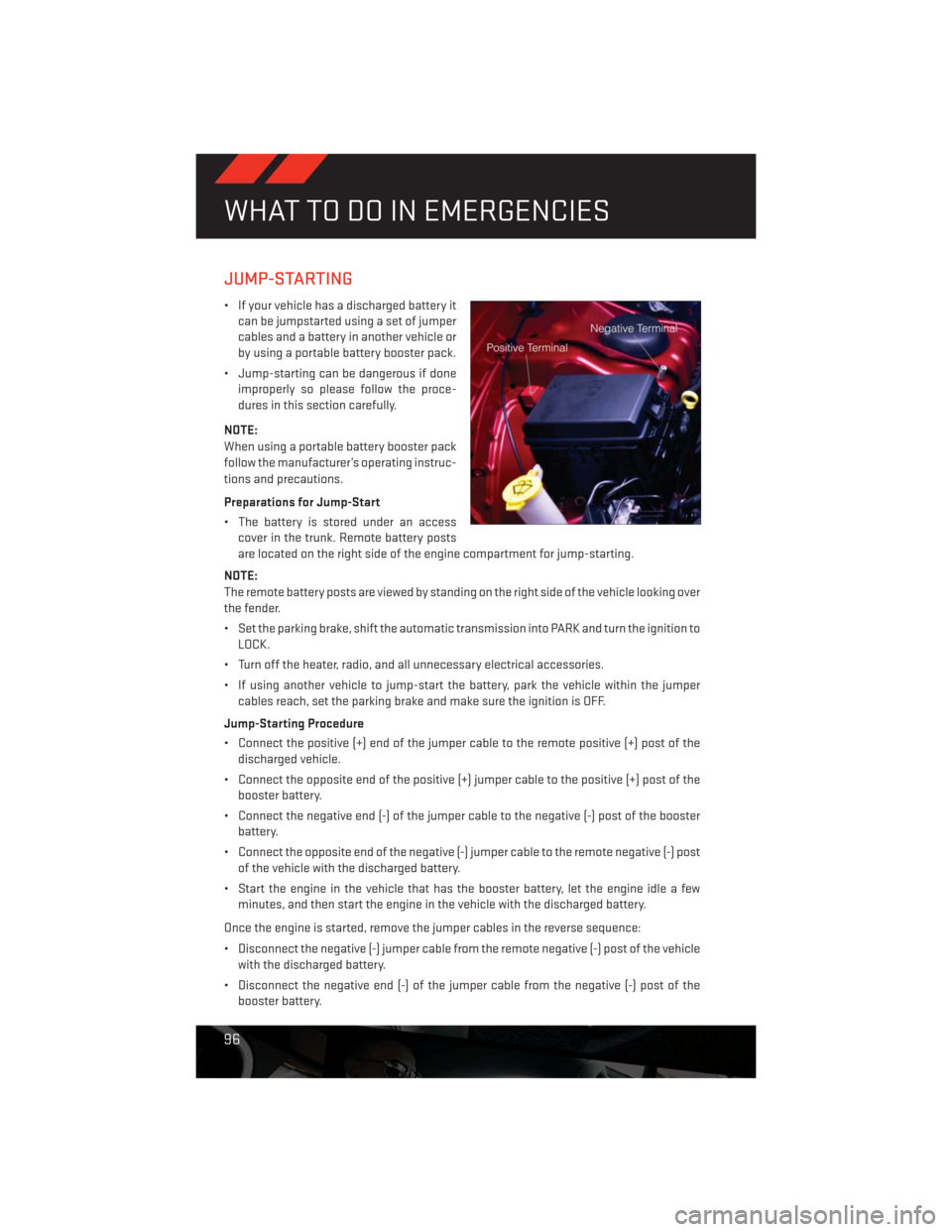
• The battery is stored under an access
cover in the trunk. Remote battery posts
are located on the right side of the engine compartment for jump-starting.
NOTE:
The remote battery posts are viewed by standing on the right side of the vehicle looking over
the fender.
• Set the parking brake, shift the automatic transmission into PARK and turn the ignition to
LOCK.
• Turn off the heater, radio, and all unnecessary electrical accessories.
• If using another vehicle to jump-start the battery, park the vehicle within the jumper
cables reach, set the parking brake and make sure the ignition is OFF.
Jump-Starting Procedure
• Connect the positive (+) end of the jumper cable to the remote positive (+) post of the
discharged vehicle.
• Connect the opposite end of the positive (+) jumper cable to the positive (+) post of the
booster battery.
• Connect the negative end (-) of the jumper cable to the negative (-) post of the booster
battery.
• Connect the opposite end of the negative (-) jumper cable to the remote negative (-) post
of the vehicle with the discharged battery.
• Start the engine in the vehicle that has the booster battery, let the engine idle a few
minutes, and then start the engine in the vehicle with the discharged battery.
Once the engine is started, remove the jumper cables in the reverse sequence:
• Disconnect the negative (-) jumper cable from the remote negative (-) post of the vehicle
with the discharged battery.
• Disconnect the negative end (-) of the jumper cable from the negative (-) post of the
booster battery.
WHAT TO DO IN EMERGENCIES
96
Page 99 of 140
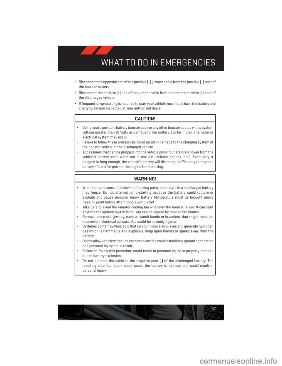
• Disconnect the opposite end of the positive (+) jumper cable from the positive (+) post of
the booster battery.
• Disconnect the positive (+) end of the jumper cable from the remote positive (+) post of
the discharged vehicle.
• If frequent jump-starting is required to start your vehicle you should have the battery and
charging system inspected at your authorized dealer.
CAUTION!
• Do not use a portable battery booster pack or any other booster source with a system
voltage greater than 12 Volts or damage to the battery, starter motor, alternator or
electrical system may occur.
• Failure to follow these procedures could result in damage to the charging system of
the booster vehicle or the discharged vehicle.
• Accessories that can be plugged into the vehicle power outlets draw power from the
vehicle’s battery, even when not in use (i.e., cellular phones, etc.). Eventually, if
plugged in long enough, the vehicle’s battery will discharge sufficiently to degrade
battery life and/or prevent the engine from starting.
WARNING!
• When temperatures are below the freezing point, electrolyte in a discharged battery
may freeze. Do not attempt jump-starting because the battery could rupture or
explode and cause personal injury. Battery temperature must be brought above
freezing point before attempting a jump-start.
• Take care to avoid the radiator cooling fan whenever the hood is raised. It can start
anytime the ignition switch is on. You can be injured by moving fan blades.
• Remove any metal jewelry, such as watch bands or bracelets, that might make an
inadvertent electrical contact. You could be severely injured.
• Batteries contain sulfuric acid that can burn your skin or eyes and generate hydrogen
gas which is flammable and explosive. Keep open flames or sparks away from the
battery.
• Do not allow vehicles to touch each other as this could establish a ground connection
and personal injury could result.
• Failure to follow this procedure could result in personal injury or property damage
due to battery explosion.
• Do not connect the cable to the negative post(-)of the discharged battery. The
resulting electrical spark could cause the battery to explode and could result in
personal injury.
WHAT TO DO IN EMERGENCIES
97
Page 128 of 140
Airbag...................14
Air Conditioning.............29
Alarm (Security Alarm)..........13
Arming Theft System (Security Alarm) . .13
Automatic Headlights..........24
Automatic Temperature Control (ATC) . .29
Automatic Transmission
Autostick.............26,74
Fluid Type..............106
Autostick...............26,74
AxleFluid ................106
Belts, Seat.................13
BrakeFluid................106
Break-In Recommendations,
New Vehicle..............22
Bulb Replacement............122
Calibration, Compass...........67
Change Oil Indicator...........81
ChangingAFlatTire...........84
Child Restraint..............15
Child Restraint Tether Anchors......15
ClimateControl..............29
Compass Calibration...........67
Cooling System
Coolant Capacity..........106
Cruise Control (Speed Control)......25
Cruise Light................25
Customer Assistance..........123
Defects, Reporting............124
DimmerControl..............24
Dimmer Switch, Headlight........24
Disarming, Theft System.........13
ECO....................67
Electronics
Your Vehicle's Sound System....32
Electronic Speed Control
(Cruise Control)............25
Electronic Vehicle Information
Center(EVIC) ...........67, 68
Emergency, In Case of
Brake Warning Light.........80
Freeing Vehicle When Stuck. . . .100
Jacking................84JumpStarting ............96
Overheating.............83
Engine
Break-In Recommendations.....22
Compartment ............103
JumpStarting ............96
Oil Selection.............106
Overheating.............83
Starting..............11, 12
Stopping..............11, 12
Event Data Recorder...........101
Exterior Lights..............122
Flat Tire Changing............84
Fluid Capacities.............106
Fluids ..................106
FogLights.................24
Folding Rear Seat.............20
Freeing A Stuck Vehicle.........100
Front Heated Seats............20
Fuel
Filler Cap (Gas Cap)..........81
Specifications
............106
Fuse ...................118
Fuses...................118
Garage Door Opener (HomeLink®)....69
Headlights
Automatic ..............24
Dimmer Switch............24
HighBeam ..............23
Heated Seats...............20
High Beam/Low Beam Select
(Dimmer) Switch............23
HomeLink® (Garage Door Opener)....69
Hood Release..............102
Instrument Cluster
Indicators...............7
Instrument Cluster Warning Lights....6
Intermittent Wipers (Delay Wipers)....23
Introduction................2
iPod®/USB/MP3 Control.........66
Bluetooth Streaming Audio.....66
INDEX
126
Page 129 of 140
Jacking Instructions...........86
Jack Location..............84
Jack Operation..............86
JumpStarting ..............96
KeyFob...................8
Key Fob Programmable Features.....68
Keyless Enter-N-Go............9
Lock/Unlock.............10
Starting/Stopping .........11, 12
Lane Change Assist...........23
Lap/Shoulder Belts............13
LATCH (Lower Anchors and Tether
for CHildren)..............15
Lights
Tire Pressure Monitoring (TPMS) . . .78
Warning (Instrument Cluster
Description)..............6
Maintenance Record.........114, 117
Maintenance Schedule.......110, 115
Malfunction Indicator Light
(CheckEngine) ............80
MOPAR® Accessories..........125
Navigation Voice Prompt Volume. . .44, 54
New Vehicle Break-In Period.......22
OilChangeIndicator ...........81
Oil Change Indicator, Reset........81
Oil, Engine
Capacity...............106
Outlet
Power .................72
Overheating, Engine...........83
Placard, Tire and Loading Information. .121
Power
Outlet (Auxiliary Electrical Outlet)...72
Seats .................18
Steering...............106
Power Sunroof..............30
Preparation for Jacking.........86
Programmable Electronic
Features..............68,76Rain Sensitive Wiper System.......23
Rear Seat, Folding............20
Recreational Towing...........73
Remote Starting System..........9
Replacement Bulbs...........122
Reporting Safety Defects........124
Rocking Vehicle When Stuck......100
Schedule, Maintenance.........110
Seat Belts.................13
Seats...................18
Adjustment..............18
Heated................20
Power .................18
Rear Folding.............20
Security Against Theft..........13
Shift Lever Override............98
Signals, Turn...............23
SpareTire.................84
Spark Plugs...............106
Speed Control
Accel/Decel.............25
Cancel................25
Resume ...............25
Set ..................25
Starting
Remote ................9
Steering
Tilt Column..............21
Steering Wheel Audio Controls......60
Stuck, Freeing..............100
Temperature Control, Automatic (ATC) . .29
Theft System Arming...........13
Theft System Disarming.........13
Tilt Steering Column...........21
TIREFIT..................90
Tires
Air Pressure.............121
Changing.............84,86
Flat Changing............84
Jacking................86
SpareTire ..............84
Towing...................73
Disabled Vehicle...........99
Recreational.............73
INDEX
127
Page 132 of 140
UTILITY
• How do I know how much I can tow with my Dodge Challenger? pg. 73
WHAT TO DO IN EMERGENCIES
• What do I do if my TPMS warning light is blinking? pg. 78
• How do I change a flat tire? pg. 84
• How do I use my Tirefit kit? pg. 91
• How do I Jump-Start my vehicle? pg. 96
MAINTAINING YOUR VEHICLE
• Where is my Fuse Block located? pg. 118
• What type of oil do I use? pg. 106
• How often should I change my engine’s oil? pg. 110
• What should my tire pressure be set at? pg. 121
FAQ (How To?)
130