maintenance DODGE CHALLENGER 2015 3.G Owners Manual
[x] Cancel search | Manufacturer: DODGE, Model Year: 2015, Model line: CHALLENGER, Model: DODGE CHALLENGER 2015 3.GPages: 603, PDF Size: 14.97 MB
Page 3 of 603
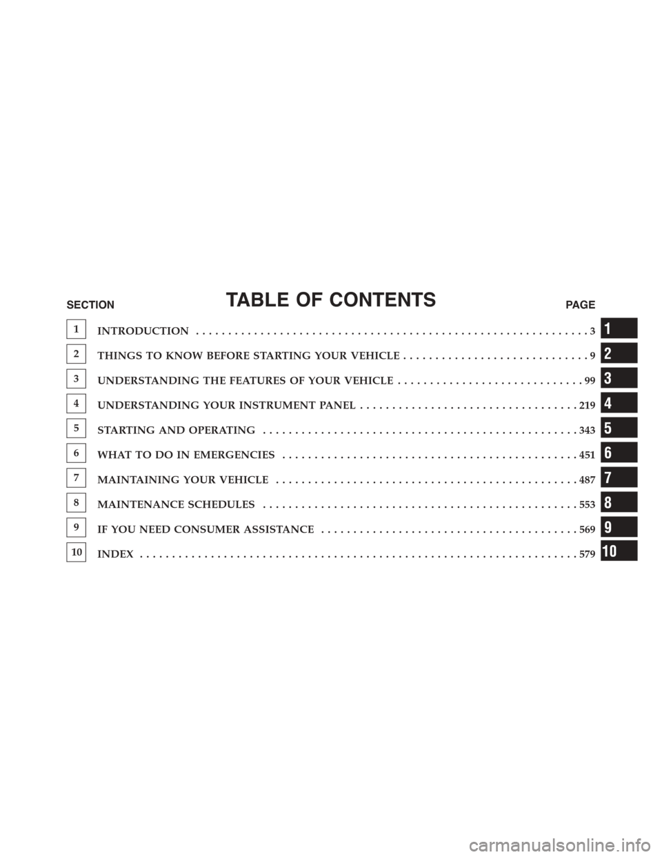
TABLE OF CONTENTSSECTIONPAGE
1INTRODUCTION.............................................................3
2THINGS TO KNOW BEFORE STARTING YOUR VEHICLE.............................9
3UNDERSTANDING THE FEATURES OF YOUR VEHICLE. . . . . . . . . . . . . . . . . . . . . . . . . . . . . 99
4UNDERSTANDING YOUR INSTRUMENT PANEL. . . . . . . . . . . . . . . . . . . . . . . . . . . . . . . . . . 219
5STARTING AND OPERATING. . . . . . . . . . . . . . . . . . . . . . . . . . . . . . . . . . . . . . . . . . . . . . . . . 343
6WHAT TO DO IN EMERGENCIES. . . . . . . . . . . . . . . . . . . . . . . . . . . . . . . . . . . . . . . . . . . . . . 451
7MAINTAINING YOUR VEHICLE. . . . . . . . . . . . . . . . . . . . . . . . . . . . . . . . . . . . . . . . . . . . . . . 487
8MAINTENANCE SCHEDULES. . . . . . . . . . . . . . . . . . . . . . . . . . . . . . . . . . . . . . . . . . . . . . . . . 553
9IF YOU NEED CONSUMER ASSISTANCE. . . . . . . . . . . . . . . . . . . . . . . . . . . . . . . . . . . . . . . . 569
10INDEX. . . . . . . . . . . . . . . . . . . . . . . . . . . . . . . . . . . . . . . . . . . . . . . . . . . . . . . . . . . . . . . . . . . . 579
1
2
3
4
5
6
7
8
9
10
Page 6 of 603

INTRODUCTION
Congratulations on selecting your new Chrysler Group
LLC vehicle. Be assured that it represents precision
workmanship, distinctive styling, and high quality - all
essentials that are traditional to our vehicles.
This Owner’s Manual has been prepared with the assis-
tance of service and engineering specialists to acquaint
you with the operation and maintenance of your vehicle.
It is supplemented by Warranty Information, and various
customer-oriented documents. Please take the time to
read these publications carefully. Following the instruc-
tions and recommendations in this manual will help
assure safe and enjoyable operation of your vehicle.
NOTE: After reviewing the owner information, it
should be stored in the vehicle for convenient referenc-
ing and remain with the vehicle when sold.
When it comes to service, remember that your authorized
dealer knows your vehicle best, has factory-trained tech-
nicians and genuine parts, and cares about your satisfac-
tion.
HOW TO USE THIS MANUAL
Consult the Table of Contents to determine which section
contains the information you desire.
Since the specification of your vehicle depends on the
items of equipment ordered, certain descriptions and
illustrations may differ from your vehicle’s equipment.
The detailed index at the back of this Owner’s Manual
contains a complete listing of all subjects.
Consult the following table for a description of the
symbols that may be used on your vehicle or throughout
this Owner’s Manual:
4INTRODUCTION
Page 67 of 603
System Reset Procedure
In order to reset the Enhanced Accident Response System
functions after an event, the ignition switch must be
changed from ignition START or ON/RUN to ignition
OFF.
Air Bag Warning Light
The air bags must be ready to inflate for your protection
in a collision. The Occupant Restraint Control-
ler (ORC) monitors the internal circuits and
interconnecting wiring associated with air bag
system electrical components.
The ORC monitors the readiness of the electronic parts of
the air bag system whenever the ignition switch is in the
START or ON/RUN position. If the ignition switch is in
the OFF position or in the ACC position, the air bag
system is not on and the air bags will not inflate.
The ORC contains a backup power supply system that
may deploy the air bags even if the battery loses power or
it becomes disconnected prior to deployment.
The ORC turns on the Air Bag Warning Light in the
instrument panel for approximately four to eight seconds
for a self-check when the ignition switch is first turned to
the ON/RUN position. After the self-check, the Air Bag
Warning Light will turn off. If the ORC detects a mal-
function in any part of the system, it turns on the Air Bag
Warning Light, either momentarily or continuously. A
single chime will sound to alert you if the light comes on
again after initial startup.
The ORC also includes diagnostics that will illuminate
the instrument panel Air Bag Warning Light if a malfunc-
tion is detected that could affect the air bag system. The
diagnostics also record the nature of the malfunction.
While the air bag system is designed to be maintenance
2
THINGS TO KNOW BEFORE STARTING YOUR VEHICLE 65
Page 104 of 603
▫To Vary The Speed Setting...............165
▫Setting The Following Distance In ACC......167
▫Overtake Aid........................171
▫Adaptive Cruise Control (ACC) Menu.......172
▫Display Warnings And Maintenance........173
▫Precautions While Driving With ACC.......175
▫General Information....................179
▫Normal (Fixed Speed) Electronic Speed Control
Mode..............................179
!FORWARD COLLISION WARNING (FCW) — IF
EQUIPPED...........................183
▫Forward Collision Warning (FCW) Operation . .183
▫Turning FCW ON Or OFF...............184
▫Changing FCW Status..................185
▫Service FCW Warning..................186
!PARKSENSE® REAR PARK ASSIST — IF
EQUIPPED...........................186
▫ParkSense® Sensors....................186
▫ParkSense® Warning Display.............187
▫ParkSense® Display....................187
▫Enabling And Disabling ParkSense®........192
▫Service The ParkSense® Rear Park Assist
System.............................192
▫Cleaning The ParkSense® System..........193
▫ParkSense® System Usage Precautions.......193
!PARKVIEW® REAR BACK UP CAMERA — IF
EQUIPPED...........................195
!OVERHEAD CONSOLE..................198
102 UNDERSTANDING THE FEATURES OF YOUR VEHICLE
Page 105 of 603
▫Courtesy/Reading Lights...............198
▫Sunglasses Storage....................198
!GARAGE DOOR OPENER — IF EQUIPPED . . .199
▫Before You Begin Programming HomeLink® . .200
▫Programming A Rolling Code.............200
▫Programming A Non-Rolling Code.........202
▫Canadian/Gate Operator Programming......204
▫Using HomeLink®....................205
▫Security............................205
▫Troubleshooting Tips...................206
▫General Information....................207
!POWER SUNROOF — IF EQUIPPED........208
▫Opening Sunroof — Express..............209
▫Opening Sunroof — Manual Mode.........209
▫Closing Sunroof — Express...............209
▫Closing Sunroof — Manual Mode..........209
▫Pinch Protect Feature...................210
▫Venting Sunroof — Express..............210
▫Sunshade Operation....................210
▫Wind Buffeting.......................210
▫Sunroof Maintenance...................211
▫Ignition Off Operation..................211
!ELECTRICAL POWER OUTLETS...........211
!CUPHOLDERS........................215
▫Front Cupholders.....................215
▫Rear Cupholders.....................216
3
UNDERSTANDING THE FEATURES OF YOUR VEHICLE 103
Page 175 of 603
Display Warnings And Maintenance
“Wipe Front Radar Sensor In Front Of Vehicle”
Warning
The “ACC/FCW Unavailable Wipe Front Radar Sensor”
warning will display and also a chime will indicate when
conditions temporarily limit system performance.
This most often occurs at times of poor visibility, such as
in snow or heavy rain. The ACC system may also become
temporarily blinded due to obstructions, such as mud,
dirt or ice. In these cases, the DID will display “ACC/
FCW Unavailable Wipe Front Radar Sensor” and the
system will deactivate.
The “ACC/FCW Unavailable Wipe Front Radar Sensor”
message can sometimes be displayed while driving in
highly reflective areas (i.e. tunnels with reflective tiles, or
ice and snow). The ACC system will recover after the
vehicle has left these areas. Under rare conditions, when
the radar is not tracking any vehicles or objects in its path
this warning may temporarily occur.
NOTE:If the “ACC/FCW Unavailable Wipe Front Radar
Sensor” warning is active Normal (Fixed Speed) Cruise
Control is still available. For additional information refer
to “Normal (Fixed Speed) Cruise Control Mode” in this
section.
If weather conditions are not a factor, the driver should
examine the sensor. It may require cleaning or removal of
an obstruction. The sensor is located in the center of the
vehicle behind the lower grille.
To keep the ACC System operating properly, it is impor-
tant to note the following maintenance items:
•Always keep the sensor clean. Carefully wipe the
sensor lens with a soft cloth. Be cautious not to damage
the sensor lens.
3
UNDERSTANDING THE FEATURES OF YOUR VEHICLE 173
Page 213 of 603
Sunroof Maintenance
Use only a nonabrasive cleaner and a soft cloth to clean
the glass panel.
Ignition Off Operation
The power sunroof switch will remain active for up to
approximately ten minutes after the ignition switch is
turned to the LOCK position. Opening either front door
will cancel this feature.
NOTE:Ignition Off time is programmable through the
Uconnect® System. Refer to “Uconnect® Settings/
Customer Programmable Features” in “Understanding
Your Instrument Panel” for further information.
ELECTRICAL POWER OUTLETS
Your vehicle is equipped with two 12 Volt (13 Amp)
power outlets that can be used to power cellular phones,
small electronics and other low powered electrical acces-
sories.
The 12 Volt power outlets have power available at all
times. These power outlets can also operate a conven-
tional cigar lighter unit.
NOTE:To ensure proper operation, a MOPAR® cigar
knob and element must be used.
The front power outlet is located next to the storage area
on the integrated center stack of the instrument panel.
3
UNDERSTANDING THE FEATURES OF YOUR VEHICLE 211
Page 233 of 603
As an added safety feature, your vehicle has been
equipped with a Tire Pressure Monitoring System
(TPMS) that illuminates a low tire pressure telltale when
one or more of your tires is significantly under-inflated.
Accordingly, when the low tire pressure telltale illumi-
nates, you should stop and check your tires as soon as
possible, and inflate them to the proper pressure. Driving
on a significantly under-inflated tire causes the tire to
overheat and can lead to tire failure. Under-inflation also
reduces fuel efficiency and tire tread life, and may affect
the vehicle’s handling and stopping ability.
Please note that the TPMS is not a substitute for proper
tire maintenance, and it is the driver ’s responsibility to
maintain correct tire pressure, even if under-inflation has
not reached the level to trigger illumination of the TPMS
low tire pressure telltale.
Your vehicle has also been equipped with a TPMS
malfunction indicator to indicate when the system is not
operating properly. The TPMS malfunction indicator is
combined with the low tire pressure telltale. When the
system detects a malfunction, the telltale will flash for
approximately one minute and then remain continuously
illuminated. This sequence will continue upon subse-
quent vehicle start-ups as long as the malfunction exists.
When the malfunction indicator is illuminated, the sys-
tem may not be able to detect or signal low tire pressure
as intended. TPMS malfunctions may occur for a variety
of reasons, including the installation of replacement or
alternate tires or wheels on the vehicle that prevent the
TPMS from functioning properly. Always check the
TPMS malfunction telltale after replacing one or more
tires or wheels on your vehicle, to ensure that the
replacement or alternate tires and wheels allow the TPMS
to continue to function properly.
4
UNDERSTANDING YOUR INSTRUMENT PANEL 231
Page 239 of 603
chime has sounded, to indicate the next scheduled oil
change interval. The engine oil change indicator system
is duty cycle based, which means the engine oil change
interval may fluctuate, dependent upon your personal
driving style.
Unless reset, this message will continue to display each
time you turn the ignition switch to the ON/RUN
position or cycle the ignition to the ON/RUN position if
equipped with Keyless Enter-N-Go™. To turn off the
message temporarily, push and release the OK button. To
reset the oil change indicator system (after performing
the scheduled maintenance) refer to the following proce-
dure.
Vehicles Equipped With Keyless Enter-N-Go™
1. Without pushing the brake pedal, push the ENGINE
START/STOP button and place the ignition to the
ON/RUN position (do not start the engine.)
2. Fully push the accelerator pedal, slowly, three times
within 10 seconds.
3. Without pushing the brake pedal, push the ENGINE
START/STOP button once to return the ignition to the
OFF/LOCK position.
NOTE:If the indicator message illuminates when you
start the vehicle, the oil change indicator system did not
reset. If necessary, repeat this procedure.
Secondary Method Of Navigating To The Oil Life
Screen In The DID And Holding Ok
Your vehicle is equipped with an engine oil change
indicator system. The “Oil Change Required” message
will flash in the DID display for approximately 10
seconds after a single chime has sounded, to indicate the
next scheduled oil change interval. The engine oil change
indicator system is duty cycle based, which means the
engine oil change interval may fluctuate, dependent
upon your personal driving style.
4
UNDERSTANDING YOUR INSTRUMENT PANEL 237
Page 326 of 603
The operator can also select the direction of the airflow
by selecting one of the available mode settings. A/C
operation and Recirculation control can also be manually
selected in Manual operation.
NOTE:Each of these features operates independently
from each other. If any feature is controlled manually,
temperature control will continue to operate automati-
cally.
Operating Tips
NOTE:Refer to the chart at the end of this section for
suggested control settings for various weather condi-
tions.
Summer Operation
The engine cooling system must be protected with a
high-quality antifreeze coolant to provide proper corro-
sion protection and to protect against engine overheating.
A solution of 50% OAT (Organic Additive Technology)
coolant that meets the requirements of Chrysler Material
Standard MS-12106 and 50% water is recommended.
Refer to “Maintenance Procedures” in “Maintaining Your
Vehicle” for proper coolant selection.
Winter Operation
Use of the air Recirculation mode during winter months
is not recommended because it may cause window
fogging.
Vacation Storage
Any time you store your vehicle or keep it out of service
(i.e., vacation) for two weeks or more, run the air
conditioning system at idle for about five minutes in the
fresh air and high blower setting. This will ensure
adequate system lubrication to minimize the possibility
of compressor damage when the system is started again.
324 UNDERSTANDING YOUR INSTRUMENT PANEL