light DODGE CHALLENGER 2015 3.G User Guide
[x] Cancel search | Manufacturer: DODGE, Model Year: 2015, Model line: CHALLENGER, Model: DODGE CHALLENGER 2015 3.GPages: 220, PDF Size: 30.96 MB
Page 3 of 220
INTRODUCTION/WELCOME
WELCOME FROM CHRYSLERGROUP LLC..................3
CONTROLS AT A GLANCE
DRIVER COCKPIT...............6INSTRUMENT CLUSTER...........8
GETTING STARTED
KEY FOB . . . . . . . . . . . . . . . . . . . 10REMOTE START . . . . . . . . . . . . . . . 12KEYLESS ENTER-N-GO™.........12VEHICLE SECURITY ALARM........16SEAT BELT SYSTEMS............17SUPPLEMENTAL RESTRAINT SYSTEM(SRS) — AIR BAGS.............18CHILD RESTRAINTS............20HEAD RESTRAINTS.............24FRONT SEATS................25REAR SEAT..................28HEATED/VENTILATED SEATS........29HEATED STEERING WHEEL........30TILT/TELESCOPING STEERINGCOLUMN...................31
OPERATING YOUR VEHICLE
ENGINE BREAK-INRECOMMENDATIONS............33TURN SIGNAL/WIPER/WASHER/HIGHBEAM LEVER.................36HEADLIGHT SWITCH............37ELECTRONIC SPEED CONTROL......38ADAPTIVE CRUISE CONTROL (ACC)....40PA R K S E N S E®REAR PARK ASSIST....43AUTOSTICK..................43SPORT MODE — WITHOUT PERFORMANCECONTROL...................45MANUAL TRANSMISSION 1 TO 4 SKIPSHIFT.....................45AUTOMATIC TEMPERATURE CONTROLS(ATC) . . . . . . . . . . . . . . . . . . . . . . 46PA R K V I E W®REAR BACK-UP CAMERA . . 49BLIND SPOT MONITORING.........50POWER SUNROOF..............50WIND BUFFETING..............51
ELECTRONICS
YOUR VEHICLE'S SOUND SYSTEM....52IDENTIFYING YOUR RADIO.........54Uconnect®ACCESS.............55Uconnect®5.0 . . . . . . . . . . . . . . . . 71Uconnect®8.4A...............82Uconnect®8.4AN.............113STEERING WHEEL AUDIO CONTROLS..130DRIVER INFORMATION DISPLAY (DID)..130
PROGRAMMABLE FEATURES.......131UNIVERSAL GARAGE DOOR OPENER(HomeLink®)................132POWER OUTLETS.............134
UTILITY
TRAILER TOWING WEIGHTS (MAXIMUMTRAILER WEIGHT RATINGS).......136RECREATIONAL TOWING (BEHINDMOTORHOME, ETC.)............136
SRT
AUTOSTICK.................137DRIVE MODES................138SRT PERFORMANCE FEATURES.....139Uconnect®SRT PERFORMANCE PAGES . . 142SUMMER/THREE-SEASON TIRES....144
WHAT TO DO IN EMERGENCIES
ROADSIDE ASSISTANCE..........145INSTRUMENT CLUSTER WARNINGLIGHTS....................145INSTRUMENT CLUSTER INDICATORLIGHTS...................150IF YOUR ENGINE OVERHEATS......151JACKING AND TIRE CHANGING.....152TIRE SERVICE KIT.............158BATTERY LOCATION............164JUMP-STARTING..............164FREEING A STUCK VEHICLE.......167MANUAL PARK RELEASE — 8 SPEEDTRANSMISSION..............168TOWING A DISABLED VEHICLE.....169EVENT DATA RECORDER (EDR).....171
MAINTAINING YOUR VEHICLE
OPENING THE HOOD...........172ENGINE COMPARTMENT.........174DODGE FLUID CAPACITIES........182FLUIDS, LUBRICANTS AND GENUINEPA RT S — D O D G E.............182FLUID CAPACITIES — SRT........184FLUIDS, LUBRICANTS AND GENUINEPA RT S — S RT . . . . . . . . . . . . . . . 1 8 5MAINTENANCE PROCEDURES......186MAINTENANCE SCHEDULE —3.6L AND 5.7L...............186MAINTENANCE SCHEDULE —6.2L SUPERCHARGED AND 6.4L....191FUSES....................198SUMMER/THREE-SEASON TIRES....203TIRE PRESSURES.............203SPARE TIRES — IF EQUIPPED......204WHEEL AND WHEEL TRIM CARE....205REPLACEMENT BULBS..........206
TABLE OF CONTENTS
Page 8 of 220
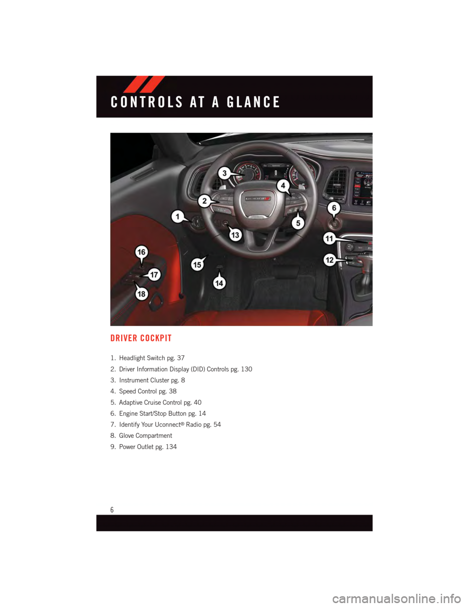
DRIVER COCKPIT
1. Headlight Switch pg. 37
2. Driver Information Display (DID) Controls pg. 130
3. Instrument Cluster pg. 8
4. Speed Control pg. 38
5. Adaptive Cruise Control pg. 40
6. Engine Start/Stop Button pg. 14
7. Identify Your Uconnect®Radio pg. 54
8. Glove Compartment
9. Power Outlet pg. 134
CONTROLS AT A GLANCE
6
Page 10 of 220
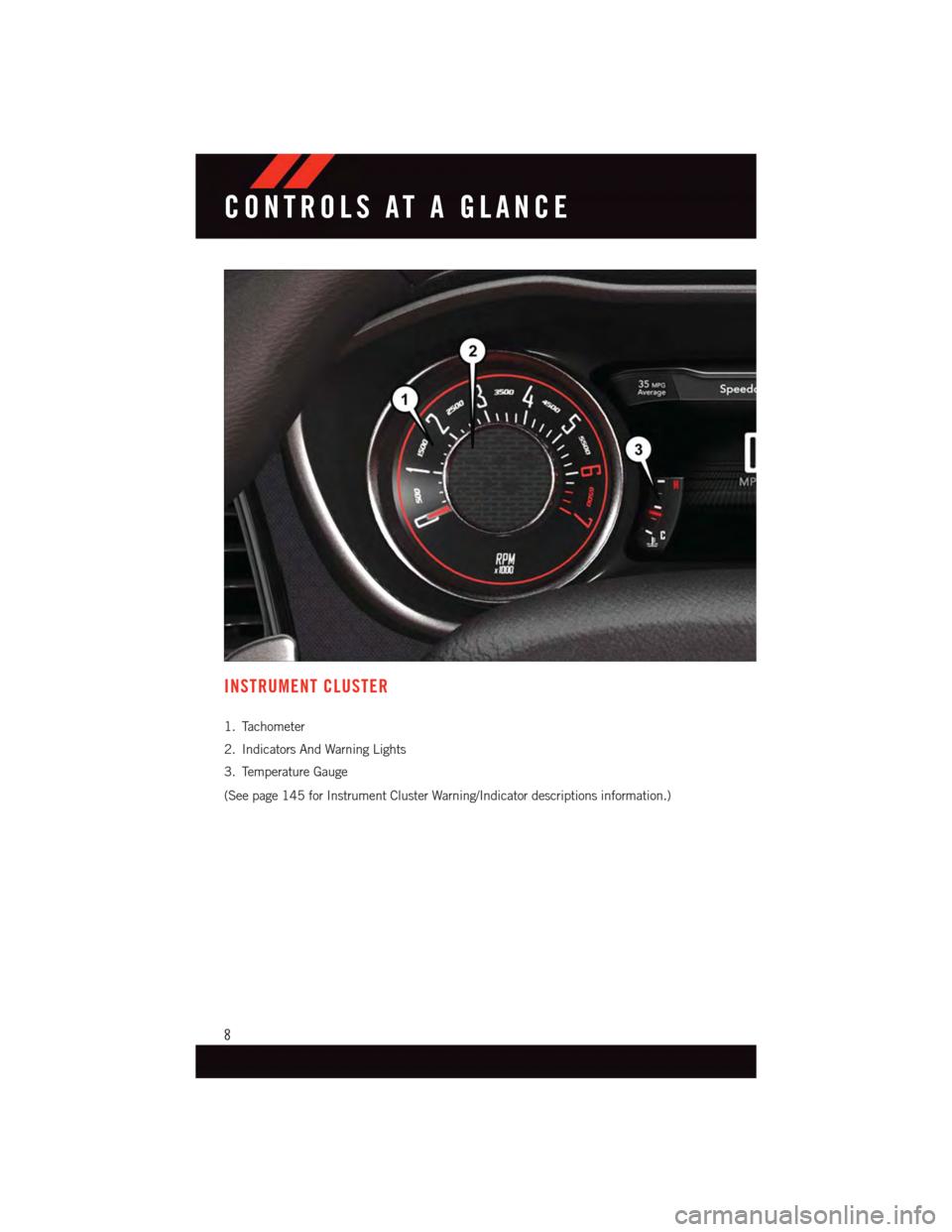
INSTRUMENT CLUSTER
1. Tachometer
2. Indicators And Warning Lights
3. Temperature Gauge
(See page 145 for Instrument Cluster Warning/Indicator descriptions information.)
CONTROLS AT A GLANCE
8
Page 11 of 220
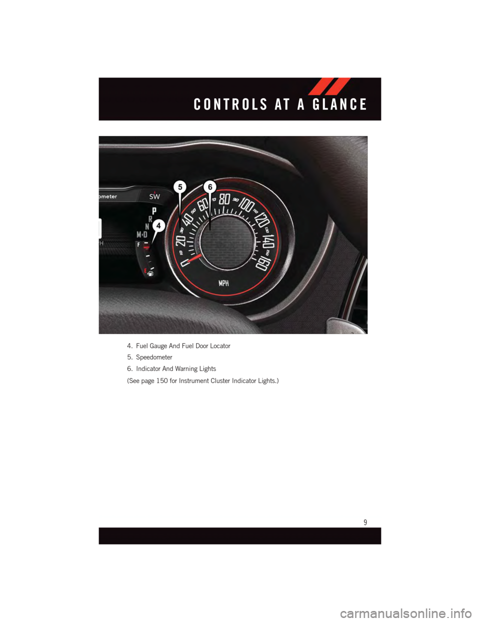
4. Fuel Gauge And Fuel Door Locator
5. Speedometer
6. Indicator And Warning Lights
(See page 150 for Instrument Cluster Indicator Lights.)
CONTROLS AT A GLANCE
9
Page 12 of 220
KEY FOB
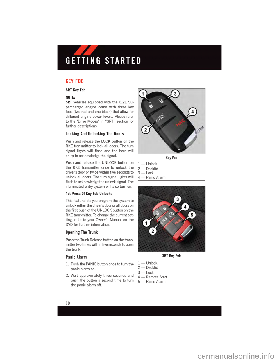
SRT Key Fob
NOTE:
SRTvehicles equipped with the 6.2L Su-
percharged engine come with three key
fobs (two red and one black) that allow for
different engine power levels. Please refer
to the "Drive Modes" in “SRT” section for
further descriptions
Locking And Unlocking The Doors
Push and release the LOCK button on the
RKE transmitter to lock all doors. The turn
signal lights will flash and the horn will
chirp to acknowledge the signal.
Push and release the UNLOCK button on
the RKE transmitter once to unlock the
driver's door or twice within five seconds to
unlock all doors. The turn signal lights will
flash to acknowledge the unlock signal. The
illuminated entry system will also turn on.
1st Press Of Key Fob Unlocks
This feature lets you program the system to
unlock either the driver's door or all doors on
the first push of the UNLOCK button on the
RKE transmitter. To change the current set-
ting, refer to your Owner's Manual on the
DVD for further information.
Opening The Trunk
Push the Trunk Release button on the trans-
mitter two times within five seconds to open
the trunk.
Panic Alarm
1. Push the PANIC button once to turn the
panic alarm on.
2. Wait approximately three seconds and
push the button a second time to turn
the panic alarm off.
Key Fob
1—Unlock
2—Decklid3—Lock4—PanicAlarm
SRT Key Fob
1—Unlock2—Decklid
3—Lock4—RemoteStart5—PanicAlarm
GETTING STARTED
10
Page 16 of 220
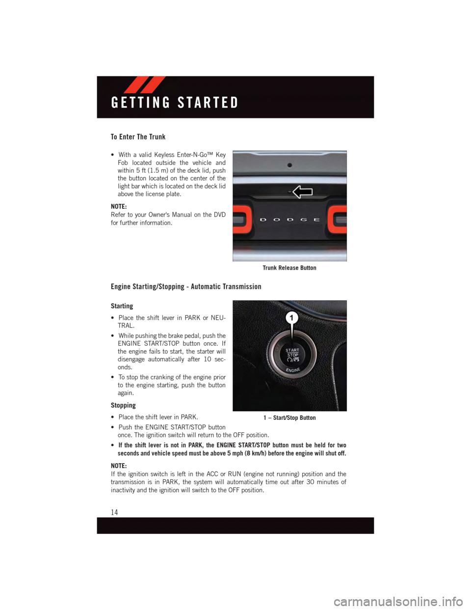
To Enter The Trunk
•WithavalidKeylessEnter-N-Go™Key
Fob located outside the vehicle and
within 5 ft (1.5 m) of the deck lid, push
the button located on the center of the
light bar which is located on the deck lid
above the license plate.
NOTE:
Refer to your Owner's Manual on the DVD
for further information.
Engine Starting/Stopping - Automatic Transmission
Starting
•PlacetheshiftleverinPARKorNEU-
TRAL.
•Whilepushingthebrakepedal,pushthe
ENGINE START/STOP button once. If
the engine fails to start, the starter will
disengage automatically after 10 sec-
onds.
•Tostopthecrankingoftheengineprior
to the engine starting, push the button
again.
Stopping
•PlacetheshiftleverinPARK.
•PushtheENGINESTART/STOPbutton
once. The ignition switch will return to the OFF position.
•If the shift lever is not in PARK, the ENGINE START/STOP button must be held for two
seconds and vehicle speed must be above 5 mph (8 km/h) before the engine will shut off.
NOTE:
If the ignition switch is left in the ACC or RUN (engine not running) position and the
transmission is in PARK, the system will automatically time out after 30 minutes of
inactivity and the ignition will switch to the OFF position.
Trunk Release Button
1 – Start/Stop Button
GETTING STARTED
14
Page 18 of 220
VEHICLE SECURITY ALARM
The Vehicle Security Alarm monitors the vehicle doors for unauthorized entry and the
Keyless Enter-N-Go™ START/STOP button for unauthorized operation. While the Vehicle
Security Alarm is armed, interior switches for door locks and decklid release are disabled.
If something triggers the alarm, the Vehicle Security Alarm will provide the following
audible and visible signals: the horn will pulse, the park lamps and/or turn signals will
flash, and the Vehicle Security Light in the instrument cluster will flash.
To Arm
•Keyless Enter-N-Go™ button installed:Push the Keyless Enter-N-Go™ START/STOP
button until the Driver Information Display (DID) indicates that the vehicle ignition is
“OFF”. Push the power door LOCK switch while the door is open, Push the Key Fob
LOCK button, or with one of the Key Fobs located outside the vehicle and within 5 ft
(1.5 m) of the driver's and passenger front door handles, push the Keyless Enter-N-
Go™ LOCK button located on the door handle.
•Keyless Enter-N-Go™ button not installed:Tu r n t h e i g n i t i o n s w i t c h t o t h e “ O F F ”
position. Push the power door lock switch while the door is open, push the Key Fob
LOCK button, or with one of the Key Fobs located outside the vehicle and within 5 ft
(1.5 m) of the driver's and passenger front door handles, push the Keyless Enter-N-
Go™ LOCK button located on the door handle.
NOTE:
After pushing the Keyless Enter-N-Go™ LOCK button, you must wait two seconds before
you can lock or unlock the vehicle via the door handle.
To Disarm
•Keyless Enter-N-Go™ button installed:Push the Key Fob UNLOCK button or with one
of the Key Fobs located outside the vehicle and within 5 ft (1.5 m) of the driver's and
passenger front door handles, grab the Keyless Enter-N-Go™ door handle and enter the
vehicle, then push the Keyless Enter-N-Go™ START/STOP button (requires at least one
valid Key Fob in the vehicle).
•Keyless Enter-N-Go™ button not installed:Push the Key Fob UNLOCK button or with
one of the Key Fobs located outside the vehicle and within 5 ft (1.5 m) of the driver's
and passenger front door handles, grab the Keyless Enter-N-Go™ door handle and
enter the vehicle, then turn the ignition to the ON/RUN position.
GETTING STARTED
16
Page 20 of 220
SUPPLEMENTAL RESTRAINT SYSTEM (SRS) — AIR BAGS
Air Bag System Components
Yo u r v e h i c l e m a y b e e q u i p p e d w i t h t h e f o l l o w i n g a i r b a g s y s t e m c o m p o n e n t s :
•OccupantRestraintController(ORC)
•AirBagWarningLight
•SteeringWheelandColumn
•InstrumentPanel
•KneeImpactBolsters
•AdvancedFrontAirBags
•SupplementalSideAirBags
•FrontandSideImpactSensors
•SeatBeltPretenioners
•SeatBeltBuckleSwitch
•SeatTrackPositionSensors
Advanced Front Air Bags
•ThisvehiclehasAdvancedFrontAirBagsforboththedriverandfrontpassengerasa
supplement to the seat belt restraint systems. The Advanced Front Air Bags will not
deploy in every type of collision.
•AdvancedFrontAirBagsaredesignedtoprovideadditionalprotectionbysupplement-
ing the seat belts. Advanced Front Air Bags are not expected to reduce the risk of injury
in rear, side, or rollover collisions.
•TheAdvancedFrontAirBagswillnotdeployinallfrontalcollisions,includingsome
that may produce substantial vehicle damage — for example, some pole collisions,
truck underrides, and angle offset collisions.
•Ontheotherhand,dependingonthetypeandlocationofimpact,AdvancedFrontAir
Bags may deploy in crashes with little vehicle front-end damage but that produce a
severe initial deceleration.
•Becauseairbagsensorsmeasurevehicledecelerationovertime,vehiclespeedand
damage by themselves are not good indicators of whether or not an air bag should have
deployed.
•Seatbeltsarenecessaryforyourprotectioninallcollisions,andalsoareneededtohelp
keep you in position, away from an inflating air bag.
•Theairbagsmustbereadytoinflateforyourprotectioninacollision.TheOccupant
Restraint Controller (ORC) monitors the internal circuits and interconnecting wiring
associated with air bag system electrical components.
GETTING STARTED
18
Page 21 of 220
•TheORCturnsontheAirBagWarningLightintheinstrumentpanelforapproximately
four to eight seconds for a self-check when the ignition switch is first turned to the
ON/RUN position. After the self-check, the Air Bag Warning Light will turn off. If the
ORC detects a malfunction in any part of the system, it turns on the Air Bag Warning
Light, either momentarily or continuously. A single chime will sound to alert you if the
light comes on again after initial startup.
•TheORCmonitorsthereadinessoftheelectronicpartsoftheairbagsystemwhenever
the ignition switch is in the START or ON/RUN position. If the ignition switch is in the
OFF position or in the ACC position, the air bag system is not on and the air bags will
not inflate.
•IftheAirBagWarningLightintheinstrumentpanelisnotonduringthefourtoeight
seconds when the ignition switch is first turned to the ON/RUN position, stays on, or
turns on while driving, have the vehicle serviced by an authorized service center
immediately.
NOTE:
If the speedometer, tachometer, or any engine related gauges are not working, the
Occupant Restraint Controller (ORC) may also be disabled. In this condition the air bags
may not be ready to inflate for your protection. Have an authorized dealer service the air
bag system immediately.
•Afteranycollision,thevehicleshouldbetakentoanauthorizeddealerimmediately.
•Donotdriveyourvehicleaftertheairbagshavedeployed.Ifyouareinvolvedinanother
collision, the air bags will not be in place to protect you.
•Ifitisnecessarytomodifytheairbagsystemforpersonswithdisabilities,contactyour
authorized dealer.
•RefertotheOwner'sManualontheDVDforfurtherdetailsregardingtheSupplemental
Restraint System (SRS).
Supplemental Side Air Bags
•ThisvehicleisequippedwithSupplementalSeat-MountedSideAirBags(SABs)
located in the outboard side of the front seats. The SABs are marked with a SRS
AIRBAG or AIRBAG label sewn into the outboard side of the seats.
•ThisvehicleisequippedwithSupplementalSideAirBagInflatableCurtains(SABICs)
located above the side windows. The trim covering the SABICs is labeled SRS AIRBAG
or AIRBAG. The SABICs may help reduce the risk of partial or complete ejection of
vehicle occupants through side windows in certain side impact events.
•TheSABICsandSABs(“SideAirBags”)aredesignedtoactivateincertainside
impacts and certain rollover events. The Occupant Restraint Controller (“ORC”)
determines whether the deployment of the Side Air Bags in a particular side impact or
rollover event is appropriate, based on the severity and type of collision. Vehicle damage
by itself is not a good indicator of whether or not Side Air Bags should have deployed.
GETTING STARTED
19
Page 39 of 220
High Beam Operation
Push the lever forward to activate the high beams. Pull the lever toward you for flash to
pass.
NOTE:
For safe driving, turn off the high beams when oncoming traffic is present to prevent
headlight glare and as a courtesy to other motorists.
HEADLIGHT SWITCH
Automatic Headlights/Parking Lights/Headlights
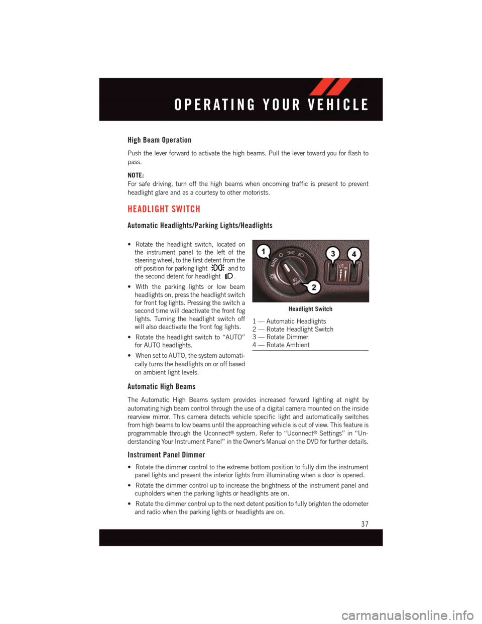
•Rotate the headlight switch, located on
the instrument panel to the left of the
steering wheel, to the first detent from the
off position for parking lightand to
the second detent for headlight.
•Withtheparkinglightsorlowbeam
headlights on, press the headlight switch
for front fog lights. Pressing the switch a
second time will deactivate the front fog
lights. Turning the headlight switch off
will also deactivate the front fog lights.
•Rotatetheheadlightswitchto“AUTO”
for AUTO headlights.
•WhensettoAUTO,thesystemautomati-
cally turns the headlights on or off based
on ambient light levels.
Automatic High Beams
The Automatic High Beams system provides increased forward lighting at night by
automating high beam control through the use of a digital camera mounted on the inside
rearview mirror. This camera detects vehicle specific light and automatically switches
from high beams to low beams until the approaching vehicle is out of view. This feature is
programmable through the Uconnect®system. Refer to “Uconnect®Settings” in “Un-
derstanding Your Instrument Panel” in the Owner's Manual on the DVD for further details.
Instrument Panel Dimmer
•Rotatethedimmercontroltotheextremebottompositiontofullydimtheinstrument
panel lights and prevent the interior lights from illuminating when a door is opened.
•Rotatethedimmercontroluptoincreasethebrightnessoftheinstrumentpaneland
cupholders when the parking lights or headlights are on.
•Rotatethedimmercontroluptothenextdetentpositiontofullybrightentheodometer
and radio when the parking lights or headlights are on.
Headlight Switch
1—AutomaticHeadlights2—RotateHeadlightSwitch3—RotateDimmer4—RotateAmbient
OPERATING YOUR VEHICLE
37