ECU DODGE CHALLENGER 2015 3.G Owner's Manual
[x] Cancel search | Manufacturer: DODGE, Model Year: 2015, Model line: CHALLENGER, Model: DODGE CHALLENGER 2015 3.GPages: 220, PDF Size: 30.96 MB
Page 136 of 220
Using HomeLink®
To o p e r a t e , p u s h a n d r e l e a s e t h e p r o g r a m m e d H o m e L i n k®button. Activation will now
occur for the programmed device (e.g., garage door opener, gate operator, security system,
entry door lock, home/office lighting, etc.). The hand-held transmitter of the device may
also be used at any time.
WARNING!
•Yourmotorizeddoororgatewillopenandclosewhileyouareprogrammingthe
universal transceiver. Do not program the transceiver if people or pets are in the
path of the door or gate.
•Donotrunyourvehicleinaclosedgarageorconfinedareawhileprogrammingthe
transceiver. Exhaust gas from your vehicle contains Carbon Monoxide (CO) which is
odorless and colorless. Carbon Monoxide is poisonous when inhaled and can cause
you and others to be severely injured or killed.
POWER OUTLETS
There are two 12 Volt electrical power outlets on this vehicle.
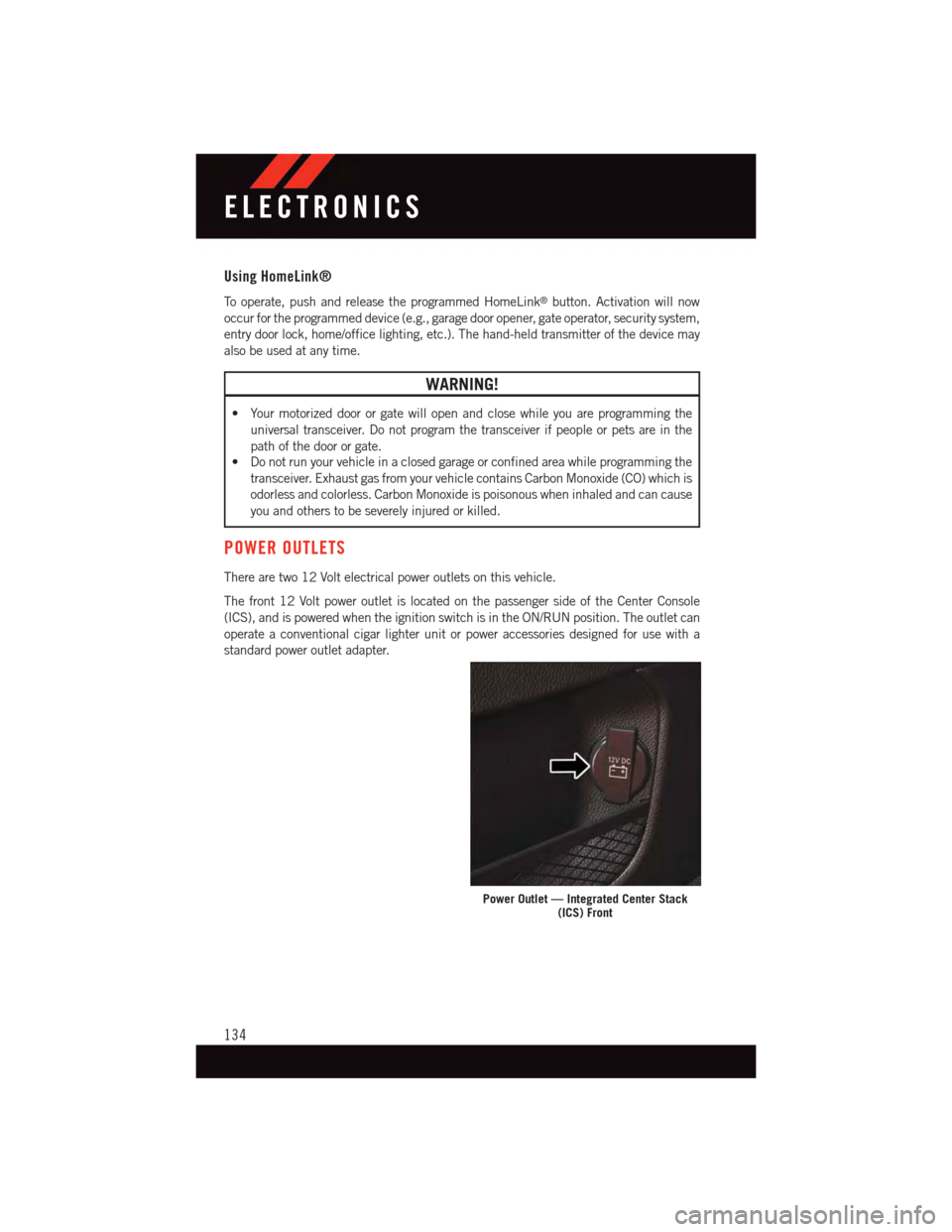
The front 12 Volt power outlet is located on the passenger side of the Center Console
(ICS), and is powered when the ignition switch is in the ON/RUN position. The outlet can
operate a conventional cigar lighter unit or power accessories designed for use with a
standard power outlet adapter.
Power Outlet — Integrated Center Stack(ICS) Front
ELECTRONICS
134
Page 143 of 220
•Engagingtheparkingbrakewilldisablethisfeature.
•Theword“READY”willdisplaywhenconditionsaremetfortheeventtobegin.
•Thedistanceandspeedmeasurementsdisplaywhiletheeventistakingplace.
•Thedistancemeasurementwillbeabortedifthebrakepedalisreleasedbeforethe
vehicle comes to a complete stop.
•ThedistanceandspeedmeasurementswillcontinuetodisplayuntiltheOKbutton is
pushed.
•PushingtheOKbutton will clear the current run and prepare the cluster to record a new
run.
Current G-Force
•Whenselected,thisscreendisplaysthecurrentG-Force(lateralandlongitudinal)along
with a friction circle that displays the directions of the forces.
Peak G-Force
When selected, this screen displays all four G-Force values (two lateral and two longitu-
dinal).
•Whenaforcegreaterthanzeroismeasured,thedisplaywillupdatethevalueasit
climbs. As the G-Force falls, the peak forces will continue to display.
•PushingtheOKbutton will clear the peak force values.
Lap Timer
When selected the Lap Timer page will show the timer always at 0:00.00 with the previous
Best and Last time data (unless the driver has cleared it via hold to Reset).
•PushingOKwillstart“current”timerfrom0:00.0.
•WhenOKispushedthetimesareupdatedaccordingly.
•AssoonasthedriverexitstheLapTimerpagesthe“current”timerwillstopandthe
time will be reset to 0:00.00.
•IfthedriverstaysontheLapTimerpagesthe“current”timerwillresetto0:00.0when
ignition is placed in the off position, or ignition placed in the ON position (or will roll
over at 59:59.99 if ever possible).
•EachtimethedriverpushesOKforaLapthatcurrenttimepopulatestheLasttimeand
also populates the 1st (top) space on the Timer History page the current time resets to
0:00.0 at every push of the OK button.
•Thetimerwillstopwhenthedrivernavigatesawayfromthispage.
Lap History
When selected, this screen displays the Lap History, and will color highlight the time that
is the best time from the Timer Page.
•EachtimethedriverpressestheOKbutton(whileontheLapTimerpage)thecurrent
Lap Time populates the 1st spot and the rest of the data shifts down.
SRT
141
Page 152 of 220
Resetting The Light After Servicing
Vehicles Equipped With Keyless Enter-N-Go™
1. Without pressing the brake pedal, push the ENGINE START/STOP button and cycle
the ignition to the ON/RUN position (do not start the engine.)
2. Fully depress the accelerator pedal, slowly, three times within 10 seconds.
3. Without pressing the brake pedal, push the ENGINE START/STOP button once to
return the ignition to the OFF/LOCK position.
Vehicles Not Equipped With Keyless Enter-N-Go™
1. Turn the ignition switch to the ON/RUN position (do not start the engine.)
2. Fully depress the accelerator pedal, slowly, three times within 10 seconds.
3. Turn the ignition switch to the OFF/LOCK position.
NOTE:
If the indicator message illuminates when you start the vehicle, the oil change indicator
system did not reset. If necessary, repeat this procedure.
INSTRUMENT CLUSTER INDICATOR LIGHTS
-TurnSignalIndicator
The arrows will flash with the exterior turn signals when the turn signal lever is operated.
Atonewillchime,andaDIDmessagewillappearifeitherturnsignalisleftonformore
than 1 mile (1.6 km).
NOTE:
If either indicator flashes at a rapid rate, check for a defective outside light bulb.
-Park/HeadlightONIndicator
This indicator will illuminate when the park lights or headlights are turned on.
-HighBeamIndicator
Indicates that headlights are on high beam.
-FrontFogLightIndicator
This indicator will illuminate when the front fog lights are on.
-VehicleSecurityLight
This light will flash rapidly for approximately 15 seconds when the vehicle security alarm
is arming. The light will flash at a slower speed continuously after the alarm is set. The
security light will also come on for about three seconds when the ignition is first turned on.
WHAT TO DO IN EMERGENCIES
150
Page 155 of 220
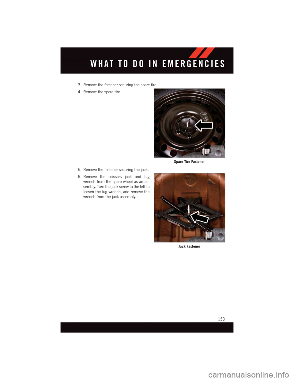
3. Remove the fastener securing the spare tire.
4. Remove the spare tire.
5. Remove the fastener securing the jack.
6. Remove the scissors jack and lug
wrench from the spare wheel as an as-
sembly. Turn the jack screw to the left to
loosen the lug wrench, and remove the
wrench from the jack assembly.
Spare Tire Fastener
Jack Fastener
WHAT TO DO IN EMERGENCIES
153
Page 170 of 220
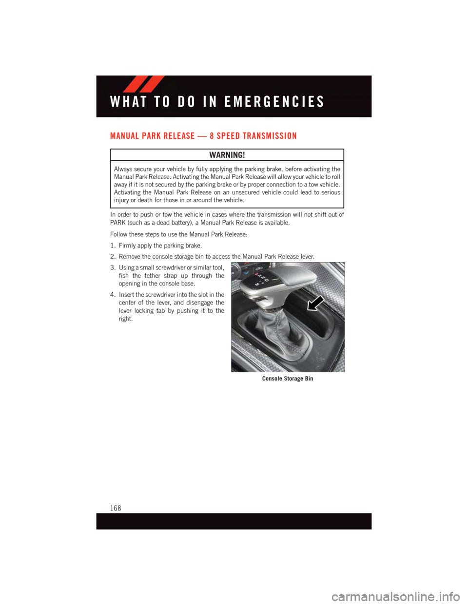
MANUAL PARK RELEASE — 8 SPEED TRANSMISSION
WARNING!
Always secure your vehicle by fully applying the parking brake, before activating the
Manual Park Release. Activating the Manual Park Release will allow your vehicle to roll
away if it is not secured by the parking brake or by proper connection to a tow vehicle.
Activating the Manual Park Release on an unsecured vehicle could lead to serious
injury or death for those in or around the vehicle.
In order to push or tow the vehicle in cases where the transmission will not shift out of
PA R K ( s u c h a s a d e a d b a t t e r y ) , a M a n u a l P a r k R e l e a s e i s a v a i l a b l e .
Follow these steps to use the Manual Park Release:
1. Firmly apply the parking brake.
2. Remove the console storage bin to access the Manual Park Release lever.
3. Using a small screwdriver or similar tool,
fish the tether strap up through the
opening in the console base.
4. Insert the screwdriver into the slot in the
center of the lever, and disengage the
lever locking tab by pushing it to the
right.
Console Storage Bin
WHAT TO DO IN EMERGENCIES
168
Page 171 of 220
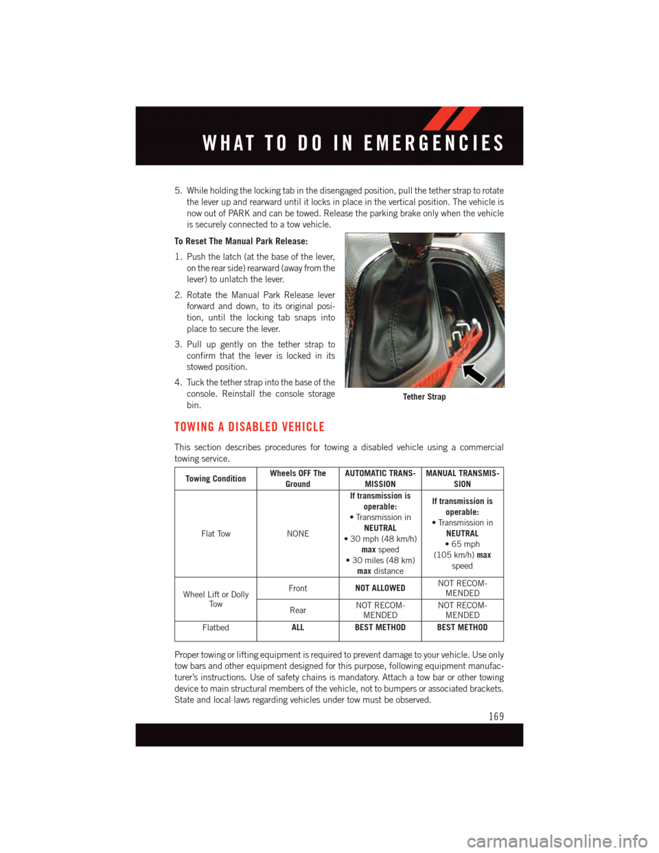
5. While holding the locking tab in the disengaged position, pull the tether strap to rotate
the lever up and rearward until it locks in place in the vertical position. The vehicle is
now out of PARK and can be towed. Release the parking brake only when the vehicle
is securely connected to a tow vehicle.
To Reset The Manual Park Release:
1. Push the latch (at the base of the lever,
on the rear side) rearward (away from the
lever) to unlatch the lever.
2. Rotate the Manual Park Release lever
forward and down, to its original posi-
tion, until the locking tab snaps into
place to secure the lever.
3. Pull up gently on the tether strap to
confirm that the lever is locked in its
stowed position.
4. Tuck the tether strap into the base of the
console. Reinstall the console storage
bin.
TOWING A DISABLED VEHICLE
This section describes procedures for towing a disabled vehicle using a commercial
towing service.
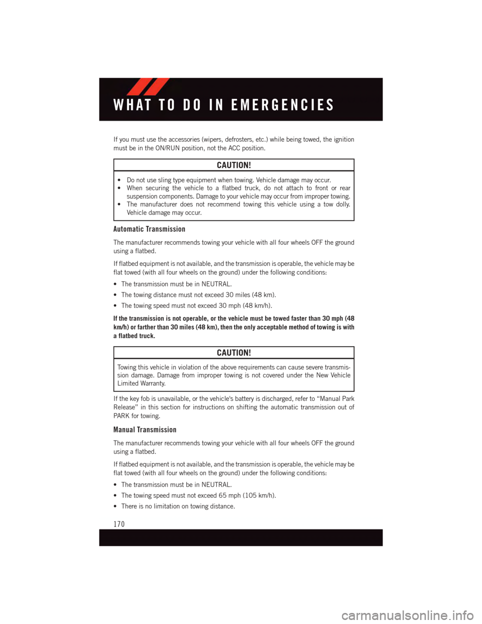
Towing ConditionWheels OFF TheGroundAUTOMATIC TRANS-MISSIONMANUAL TRANSMIS-SION
Flat TowNONE
If transmission isoperable:•TransmissioninNEUTRAL•30mph(48km/h)maxspeed•30miles(48km)maxdistance
If transmission isoperable:•TransmissioninNEUTRAL•65mph(105 km/h)maxspeed
Wheel Lift or DollyTo w
FrontNOT ALLOWEDNOT RECOM-MENDED
RearNOT RECOM-MENDEDNOT RECOM-MENDED
FlatbedALLBEST METHOD BEST METHOD
Proper towing or lifting equipment is required to prevent damage to your vehicle. Use only
tow bars and other equipment designed for this purpose, following equipment manufac-
turer’s instructions. Use of safety chains is mandatory. Attach a tow bar or other towing
device to main structural members of the vehicle, not to bumpers or associated brackets.
State and local laws regarding vehicles under tow must be observed.
Tether Strap
WHAT TO DO IN EMERGENCIES
169
Page 172 of 220
If you must use the accessories (wipers, defrosters, etc.) while being towed, the ignition
must be in the ON/RUN position, not the ACC position.
CAUTION!
•Donotuseslingtypeequipmentwhentowing.Vehicledamagemayoccur.
•Whensecuringthevehicletoaflatbedtruck,donotattachtofrontorrear
suspension components. Damage to your vehicle may occur from improper towing.
•Themanufacturerdoesnotrecommendtowingthisvehicleusingatowdolly.
Vehicle damage may occur.
Automatic Transmission
The manufacturer recommends towing your vehicle with all four wheels OFF the ground
using a flatbed.
If flatbed equipment is not available, and the transmission is operable, the vehicle may be
flat towed (with all four wheels on the ground) under the following conditions:
•ThetransmissionmustbeinNEUTRAL.
•Thetowingdistancemustnotexceed30miles(48km).
•Thetowingspeedmustnotexceed30mph(48km/h).
If the transmission is not operable, or the vehicle must be towed faster than 30 mph (48
km/h) or farther than 30 miles (48 km), then the only acceptable method of towing is with
a flatbed truck.
CAUTION!
To w i n g t h i s v e h i c l e i n v i o l a t i o n o f t h e a b o v e r e q u i r e m e n t s c a n c a u s e s e v e r e t r a n s m i s -
sion damage. Damage from improper towing is not covered under the New Vehicle
Limited Warranty.
If the key fob is unavailable, or the vehicle's battery is discharged, refer to “Manual Park
Release” in this section for instructions on shifting the automatic transmission out of
PA R K f o r t o w i n g .
Manual Transmission
The manufacturer recommends towing your vehicle with all four wheels OFF the ground
using a flatbed.
If flatbed equipment is not available, and the transmission is operable, the vehicle may be
flat towed (with all four wheels on the ground) under the following conditions:
•ThetransmissionmustbeinNEUTRAL.
•Thetowingspeedmustnotexceed65mph(105km/h).
•Thereisnolimitationontowingdistance.
WHAT TO DO IN EMERGENCIES
170
Page 200 of 220
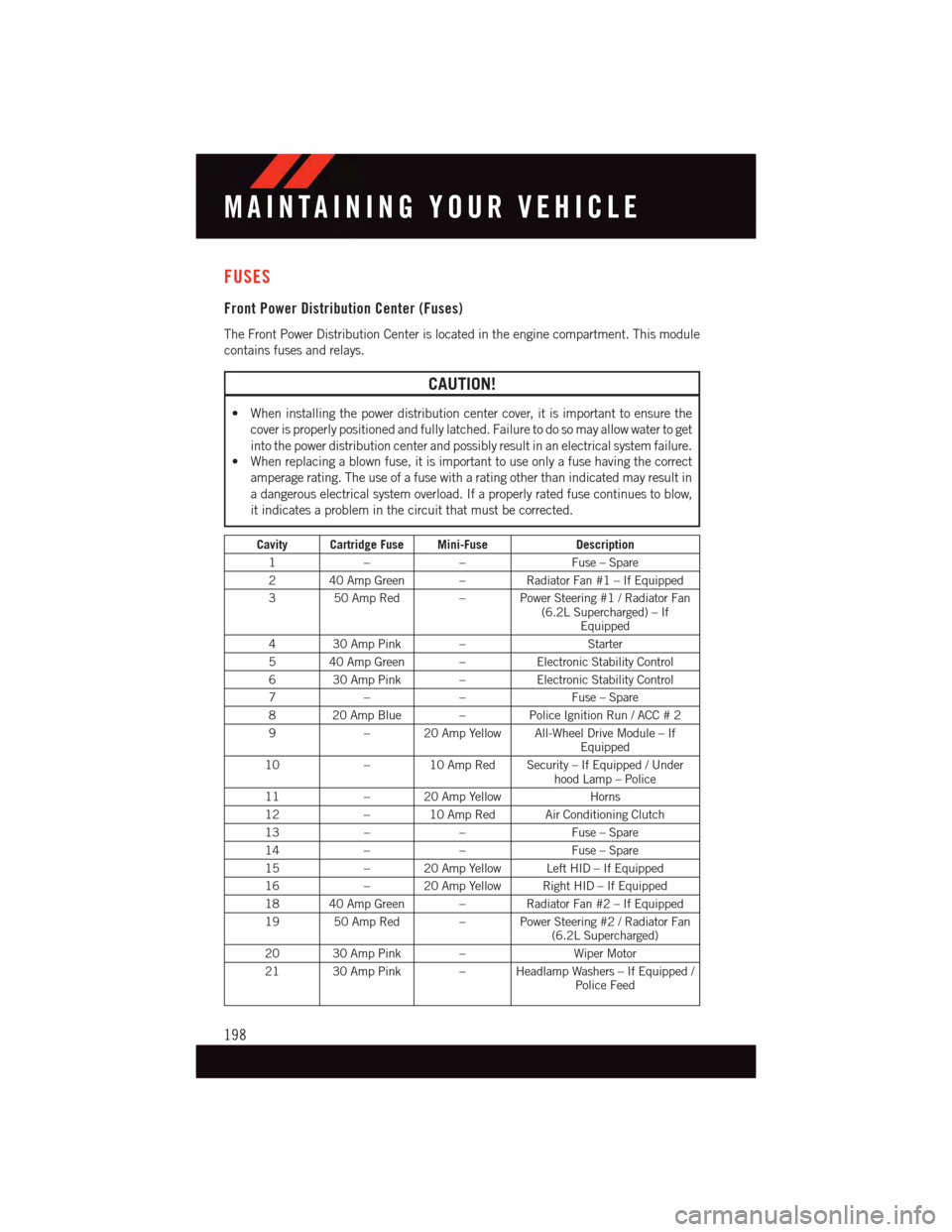
FUSES
Front Power Distribution Center (Fuses)
The Front Power Distribution Center is located in the engine compartment. This module
contains fuses and relays.
CAUTION!
•Wheninstallingthepowerdistributioncentercover,itisimportanttoensurethe
cover is properly positioned and fully latched. Failure to do so may allow water to get
into the power distribution center and possibly result in an electrical system failure.•Whenreplacingablownfuse,itisimportanttouseonlyafusehavingthecorrect
amperage rating. The use of a fuse with a rating other than indicated may result in
adangerouselectricalsystemoverload.Ifaproperlyratedfusecontinuestoblow,
it indicates a problem in the circuit that must be corrected.
Cavity Cartridge Fuse Mini-FuseDescription
1––Fuse – Spare
240AmpGreen – RadiatorFan#1–IfEquipped
350AmpRed –PowerSteering#1/RadiatorFan(6.2L Supercharged) – IfEquipped
430AmpPink –Starter
540AmpGreen –Electronic Stability Control
630AmpPink –Electronic Stability Control
7––Fuse – Spare
820AmpBlue –Police Ignition Run / ACC # 2
9–20AmpYellowAll-WheelDriveModule–IfEquipped
10–10AmpRedSecurity–IfEquipped/Underhood Lamp – Police
11–20AmpYellowHorns
12–10AmpRedAirConditioningClutch
13––Fuse – Spare
14––Fuse – Spare
15–20AmpYellowLeftHID–IfEquipped
16–20AmpYellowRightHID–IfEquipped
18 40 Amp Green – Radiator Fan #2 – If Equipped
19 50 Amp Red – Power Steering #2 / Radiator Fan(6.2L Supercharged)
20 30 Amp Pink –Wiper Motor
21 30 Amp Pink – Headlamp Washers – If Equipped /Police Feed
MAINTAINING YOUR VEHICLE
198
Page 210 of 220
•Clickonthe“ForOwners”tab,select“Owner/ServiceManuals”,thenselectyour
desired model year and vehicle from the drop down lists.
REPORTING SAFETY DEFECTS IN THE UNITED STATES
If you believe that your vehicle has a defect that could cause a collision or cause injury or
death, you should immediately inform the National Highway Traffic Safety Administration
(NHTSA) in addition to notifying the manufacturer.
If NHTSA receives similar complaints, it may open an investigation, and if it finds that a
safety defect exists in a group of vehicles, it may order a recall and remedy campaign.
However, NHTSA cannot become involved in individual problems between you, your
authorized dealer and the manufacturer.
To c o n t a c t N H T S A , y o u m a y e i t h e r c a l l t h e A u t o S a f e t y H o t l i n e t o l l f r e e a t 1 – 8 8 8 –
327–4236 (TTY: 1–800–424–9153), or go to http://www.safercar.gov; or write to:
Administrator, NHTSA, 1200 New Jersey Avenue, SE., West Building, Washington, D.C.
20590. You can also obtain other information about motor vehicle safety from
http://www.safercar.gov.
In Canada
If you believe that your vehicle has a safety defect, you should contact the Customer
Service Department immediately. Canadian customers who wish to report a safety defect
to the Canadian government should contact Transport Canada, Motor Vehicle Defect
Investigations and Recalls at 1-800-333-0510 or go to http://www.tc.gc.ca/roadsafety/.
French Canadian customers who wish to report a safety defect to the Canadian govern-
ment should contact Transport Canada, Motor Vehicle Defect Investigations and Recalls
at 1-800-333-0510 or go to http://www.tc.gc.ca/securiteroutiere/ .
CONSUMER ASSISTANCE
208
Page 214 of 220
Access
Uconnect®..............55
Access, Uconnect®...........55
Adaptive Cruise Control (ACC)
(Cruise Control) . . . . . . . . . . . .40
Adding Engine Coolant (Antifreeze) . .186
Adding Washer Fluid..........186
Air Bag
Advanced Front Air Bag.......18
Advance Front Air Bag.......18
Air Bags . . . . . . . . . . . . . . .18Air Bag Warning Light . . . . . . . .18Front Air Bag . . . . . . . . . . . .18Rollover . . . . . . . . . . . . . . .18Side Impacts.............18Air bag Light . . . . . . . . . . . . . .148Air Cleaner, Engine (Engine AirCleaner Filter)............186Air Conditioner Maintenance.....186Air Conditioning...........46,48Air Conditioning Refrigerant......186Air Conditioning System........186AlarmVehicle Security Alarm.......16Alarm (Security Alarm)......16,150Antifreeze (Engine Coolant). . .182, 184,186Disposal . . . . . . . . . . . . . .186Anti-Lock Warning Light........148APPUconnect®Access..........57Appearance Care............186Arming System (Security Alarm)....16Assistance Towing...........145Automatic Headlights.......37,151Automatic High Beams.........37Automatic Temperature Control(ATC) . . . . . . . . . . . . . . . . .46Automatic TransmissionAdding Fluid........184, 186Autostick...........43,137Fluid Type . . . . . . . . . .184, 186Autostick..............43,137Axle Fluid . . . . . . . . . . . .184, 186Axle Lubrication . . . . . . . . .184, 186
Back-Up Camera............49Battery.................186
Blind Spot Monitoring..........50Body Mechanism Lubrication.....186Brake Fluid . . . . . . . . . . . .184, 186Brakes.................186Brake System.............186Fluid Check.........184, 186Master Cylinder..........186Break-In Recommendations, NewVehicle . . . . . . . . . . . . . .33, 34Bulb Replacement...........206Bulbs, Light . . . . . . . . . . . . . .206
Capacities, Fluid.........182, 184Caps, FillerOil (Engine)............186Car Washes . . . . . . . . . . . . . . .186Change Oil Indicator..........149Changing A Flat Tire..........152Charging System Light.........147Child Restraint...........20,21Child RestraintsLower Anchors And Tethers ForChildren . . . . . . . . . . . . . . .21CleaningWheels...............186Windshield Wiper Blades.....186Climate Control . . . . . . . . . . . . .46Clock . . . . . . . . . . . . . . . . . . .71Clock Setting...............71Cluster Warning/Indicator LightsAnti-Lock Brake (ABS) Light . . .148Charging System Light......147Electronic Speed Control ONIndicator . . . . . . . . . . . . . .151Electronic Speed Control SETIndicator . . . . . . . . . . . . . .151Electronic Throttle Control (ETC)Indicator Light . . . . . . . . . . .148Engine Temperature WarningLight . . . . . . . . . . . . . . . .147Front Fog Light Indicator . . . . .150Fuel Cap/Loose Gas Cap......151High Beam Indicator.......150Malfunction Indicator Light(MIL) . . . . . . . . . . . . . . . .147Oil Pressure Warning Light . . . .148Park/Headlight ON Indicator . . .150
INDEX
212