display DODGE CHALLENGER 2015 3.G Service Manual
[x] Cancel search | Manufacturer: DODGE, Model Year: 2015, Model line: CHALLENGER, Model: DODGE CHALLENGER 2015 3.GPages: 220, PDF Size: 30.96 MB
Page 134 of 220
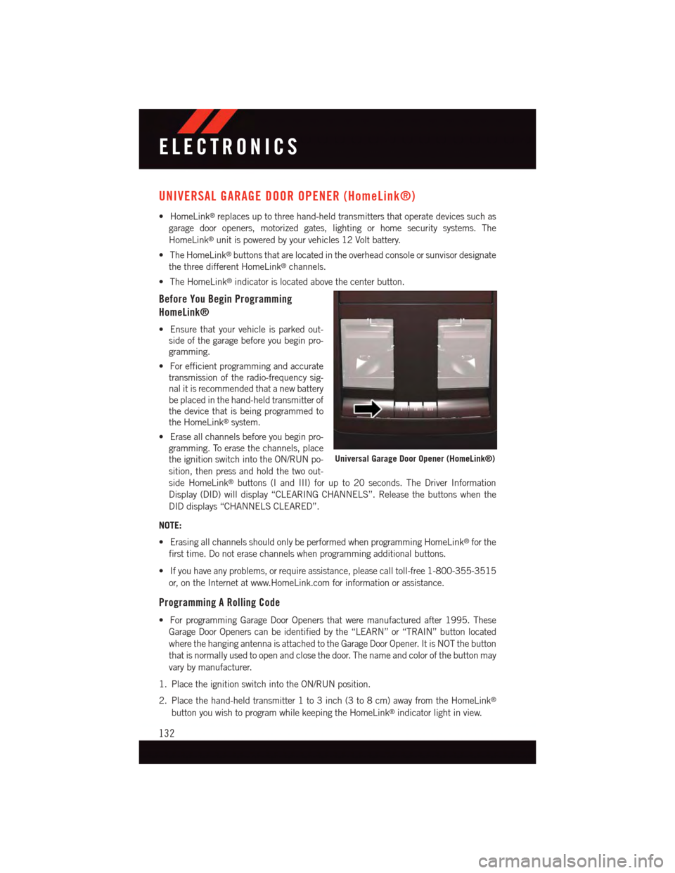
UNIVERSAL GARAGE DOOR OPENER (HomeLink®)
•HomeLink®replaces up to three hand-held transmitters that operate devices such as
garage door openers, motorized gates, lighting or home security systems. The
HomeLink®unit is powered by your vehicles 12 Volt battery.
•TheHomeLink®buttons that are located in the overhead console or sunvisor designate
the three different HomeLink®channels.
•TheHomeLink®indicator is located above the center button.
Before You Begin Programming
HomeLink®
•Ensurethatyourvehicleisparkedout-
side of the garage before you begin pro-
gramming.
•Forefficientprogrammingandaccurate
transmission of the radio-frequency sig-
nal it is recommended that a new battery
be placed in the hand-held transmitter of
the device that is being programmed to
the HomeLink®system.
•Eraseallchannelsbeforeyoubeginpro-
gramming. To erase the channels, place
the ignition switch into the ON/RUN po-
sition, then press and hold the two out-
side HomeLink®buttons (I and III) for up to 20 seconds. The Driver Information
Display (DID) will display “CLEARING CHANNELS”. Release the buttons when the
DID displays “CHANNELS CLEARED”.
NOTE:
•ErasingallchannelsshouldonlybeperformedwhenprogrammingHomeLink®for the
first time. Do not erase channels when programming additional buttons.
•Ifyouhaveanyproblems,orrequireassistance,pleasecalltoll-free1-800-355-3515
or, on the Internet at www.HomeLink.com for information or assistance.
Programming A Rolling Code
•ForprogrammingGarageDoorOpenersthatweremanufacturedafter1995.These
Garage Door Openers can be identified by the “LEARN” or “TRAIN” button located
where the hanging antenna is attached to the Garage Door Opener. It is NOT the button
that is normally used to open and close the door. The name and color of the button may
vary by manufacturer.
1. Place the ignition switch into the ON/RUN position.
2. Place the hand-held transmitter 1 to 3 inch (3 to 8 cm) away from the HomeLink®
button you wish to program while keeping the HomeLink®indicator light in view.
Universal Garage Door Opener (HomeLink®)
ELECTRONICS
132
Page 135 of 220
3. Simultaneously push and hold both the Homelink®button you want to program and
the hand-held transmitter button.
4. Continue to hold buttons until the DID display changes from “CHANNEL # TRAIN-
ING” to “CHANNEL # TRAINED”, then release both buttons.
NOTE:
If the DID displays “DID NOT TRAIN” repeat from Step 2.
5. At the garage door opener motor (in the garage), locate the “LEARN” or “TRAINING”
button. This can usually be found where the hanging antenna wire is attached to the
garage door opener motor. Firmly push and release the “LEARN” or “TRAINING”
button.
NOTE:
Yo u h a v e 3 0 s e c o n d s i n w h i c h t o i n i t i a t e t h e n e x t s t e p a f t e r t h e L E A R N b u t t o n h a s b e e n
pushed.
6. Return to the vehicle and push the programmed HomeLink®button twice (holding the
button for two seconds each time). The DID will display “CHANNEL # TRANSMIT”. If
the garage door opener/device activates, programming is complete.
NOTE:
If the device does not activate, push the button a third time (for two seconds) to complete
the training.
7. To program the remaining two HomeLink®buttons, repeat each step for each
remaining button. DO NOT erase the channels.
Programming A Non-Rolling Code
•ForprogrammingGarageDoorOpenersmanufacturedbefore1995.
1. Turn the ignition switch to the ON/RUN position.
2. Place the hand-held transmitter 1 to 3 inch (3 to 8 cm) away from the HomeLink®
button you wish to program while keeping the HomeLink®indicator light in view.
3. Simultaneously push and hold both the HomeLink®button you want to program and
the hand-held transmitter button.
4. Continue to hold buttons until the DID display changes from “CHANNEL # TRAIN-
ING” to “CHANNEL # TRAINED”, then release both buttons.
5. Push and hold the programmed HomeLink®button and observe the indicator light.
NOTE:
•IftheDIDdisplays“DIDNOTTRAIN”repeatfromStep2.
•ToprogramthetworemainingHomeLink®buttons, repeat each step for each remain-
ing button. DO NOT erase the channels.
ELECTRONICS
133
Page 139 of 220
AUTOSTICK
Steering Wheel Mounted Paddle Shifters Or Console Mounted Shifter
AutoStick is a driver-interactive transmission feature providing manual shift control,
giving you more control of the vehicle. AutoStick allows you to maximize engine braking,
eliminate undesirable upshifts and downshifts, and improve overall vehicle performance.
This system can also provide you with more control during passing, city driving, cold
slippery conditions, mountain driving, and many other situations.
Operation
When the shift lever is in the DRIVE (D) position, the transmission will operate automati-
cally, shifting between the eight available gears. To activate AutoStick, move the shift lever
into the MANUAL (M) position (beside the DRIVE position). The current transmission gear
will be displayed in the instrument cluster, along with a highlighted "M" (Manual)
indication. When the shift lever is in the MANUAL (M) position, tap the shift lever forward
(-) (or tap the (-) shift paddle on the steering wheel, if equipped) to downshift the
transmission to the next lower gear, or tap the lever rearward (+) (or tap the (+) shift
paddle, if equipped) to command an upshift.
NOTE:
Ta p p i n g o n e o f t h e s t e e r i n g w h e e l - m o u n t e d s h i f t p a d d l e s ( + / - ) , i f e q u i p p e d , w h i l e t h e s h i f t
lever is in DRIVE, will activate a temporary AutoStick mode. Tapping (-) to enter AutoStick
mode will downshift the transmission to the next lower gear, while using (+) to enter
AutoStick mode will retain the current gear. The current gear will be displayed in the
instrument cluster, but the "M" will not be highlighted. The transmission will revert back
to normal operation (if the shift lever remains in DRIVE) after a period of time, depending
on accelerator pedal activity.
In AutoStick mode, the transmission will shift up or down when (+/-) is manually selected
by the driver (using the shift lever, or the shift paddles [if equipped]), unless an engine
lugging or overspeed condition would result. It will remain in the selected gear until
another upshift or downshift is chosen, except as described below.
•IntemporaryAutoStickmode(shiftleverinDRIVE),thetransmissionwillautomatically
shift up when maximum engine speed is reached. If the accelerator is fully depressed,
the transmission will downshift when possible (based on current vehicle speed and
gear). Lack of accelerator pedal activity will cause the transmission to revert to
automatic operation.
•IfnormalAutoStickmodeisengaged(shiftleverinMANUALposition),manualgear
selection will be maintained until the shift lever is returned to DRIVE, or as described
below. The transmission will not upshift automatically at redline in this mode, nor will
downshifts be obtained if the accelerator pedal is pressed to the floor.
•Thetransmissionwillautomaticallydownshiftasthevehicleslows(topreventengine
lugging) and will display the current gear.
SRT
137
Page 141 of 220
SRT PERFORMANCE FEATURES
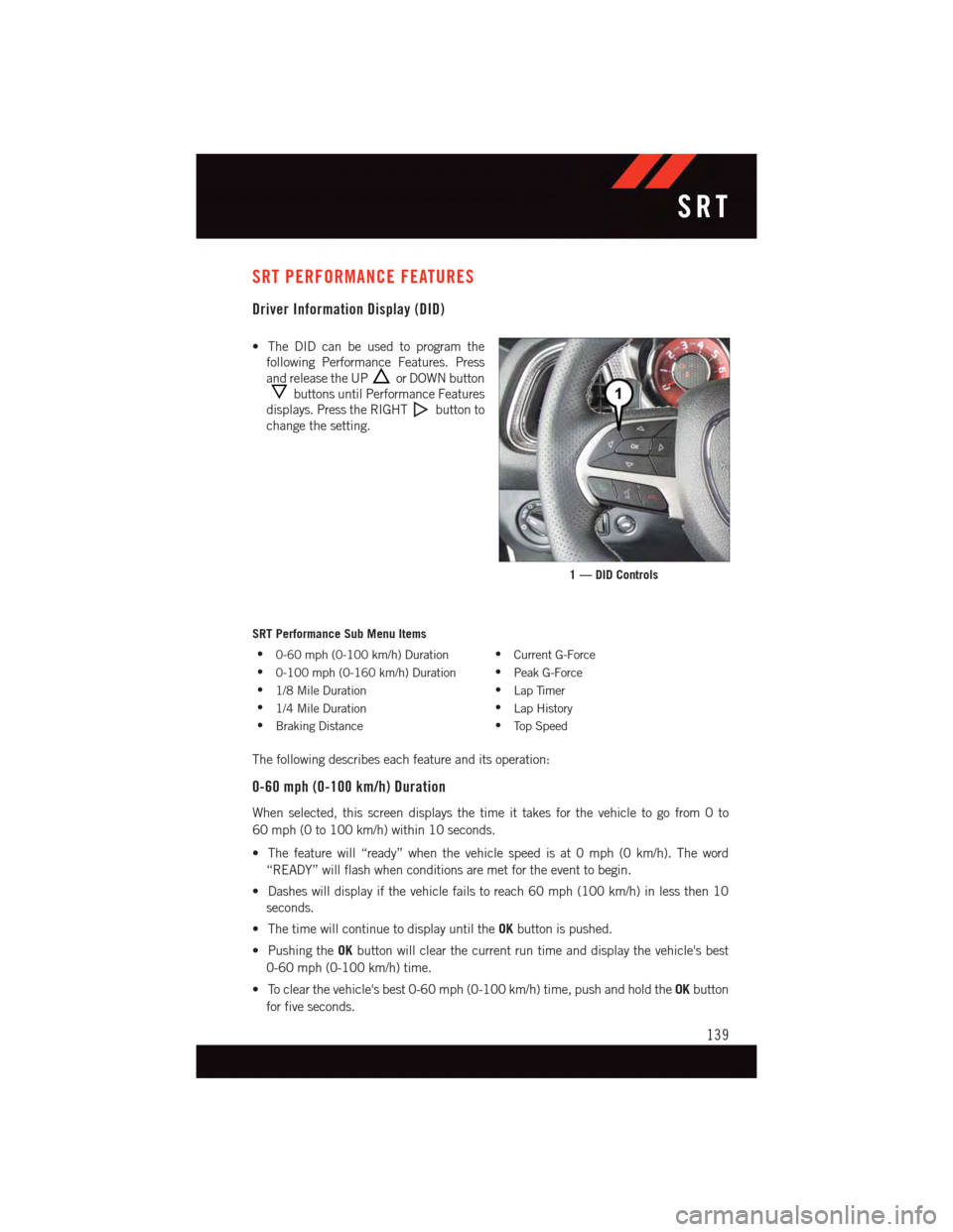
Driver Information Display (DID)
•TheDIDcanbeusedtoprogramthe
following Performance Features. Press
and release the UPor DOWN button
buttons until Performance Features
displays. Press the RIGHTbutton to
change the setting.
SRT Performance Sub Menu Items
•0-60 mph (0-100 km/h) Duration•Current G-Force
•0-100 mph (0-160 km/h) Duration•Peak G-Force
•1/8 Mile Duration•Lap Timer
•1/4 Mile Duration•Lap History
•Braking Distance•To p S p e e d
The following describes each feature and its operation:
0-60 mph (0-100 km/h) Duration
When selected, this screen displays the time it takes for the vehicle to go from 0 to
60 mph (0 to 100 km/h) within 10 seconds.
•Thefeaturewill“ready”whenthevehiclespeedisat0mph(0km/h).Theword
“READY” will flash when conditions are met for the event to begin.
•Dasheswilldisplayifthevehiclefailstoreach60mph(100km/h)inlessthen10
seconds.
•ThetimewillcontinuetodisplayuntiltheOKbutton is pushed.
•PushingtheOKbutton will clear the current run time and display the vehicle's best
0-60 mph (0-100 km/h) time.
•Toclearthevehicle'sbest0-60mph(0-100km/h)time,pushandholdtheOKbutton
for five seconds.
1 — DID Controls
SRT
139
Page 142 of 220
0-100 mph (0-160 km/h) Duration
When selected, this screen displays the time it takes for the vehicle to go from 0 to
100 mph (0 to 161 km/h) within 10 seconds.
•Thefeaturewill“ready”whenthevehiclespeedisat0mph(0km/h).Theword
“READY” will flash when conditions are met for the event to begin.
•Dasheswilldisplayifthevehiclefailstoreach0to100mph(0to161km/h)inless
then 10 seconds.
•ThetimewillcontinuetodisplayuntiltheOKbutton is pushed.
•PushingtheOKbutton will clear the current run time and display the vehicle's best 0
to 100 mph (0 to 161 km/h) time.
•Toclearthevehicle'sbest0to100mph(0to161km/h)time,pushandholdtheOK
button for five seconds.
1/8 Mile Duration
When selected, this screen displays the time it takes the vehicle to travel 1/8 mile within
30 seconds and the vehicle's speed when it reaches 1/8 mile.
•Thefeaturewill“ready”whenthevehicleisat0mph(0km/h).Theword“READY”will
flash when conditions are met for the event to begin.
•Dasheswilldisplayifthevehiclefailstoreach1/8mileinlessthen30seconds.
•ThetimeandspeedwillcontinuetodisplayuntiltheOKbutton is pushed.
•PushingtheOKbutton will clear the current run and display the vehicle's best 1/8 mile
run.
•Toclearthevehicle'sbest1/8milerun,pushandholdtheOKbutton for five seconds.
1/4 Mile Duration
When selected, this screen displays the time it takes the vehicle to travel 1/4 mile within
30 seconds and the vehicle's speed when it reaches 1/4 mile.
•Thefeaturewill“ready”whenthevehicleisat0mph(0km/h).Theword“READY”will
flash when conditions are met for the event to begin.
•Dasheswilldisplayifthevehiclefailstoreach1/4mileinlessthen30seconds.
•ThetimeandspeedwillcontinuetodisplayuntiltheOKbutton is pushed.
•PushingtheOKbutton will clear the current run and display the vehicle's best 1/4 mile
run.
•Toclearthevehicle'sbest1/4milerun,pushandholdtheOKbutton for five seconds.
Braking Distance
When selected, this screen displays the vehicle's braking distance and the speed at which
the brake pedal was depressed.
•Thisfeaturewillonlyfunctionwhenapplyingthebrakesatspeedsabove30mph
(48 km/h).
SRT
140
Page 143 of 220
•Engagingtheparkingbrakewilldisablethisfeature.
•Theword“READY”willdisplaywhenconditionsaremetfortheeventtobegin.
•Thedistanceandspeedmeasurementsdisplaywhiletheeventistakingplace.
•Thedistancemeasurementwillbeabortedifthebrakepedalisreleasedbeforethe
vehicle comes to a complete stop.
•ThedistanceandspeedmeasurementswillcontinuetodisplayuntiltheOKbutton is
pushed.
•PushingtheOKbutton will clear the current run and prepare the cluster to record a new
run.
Current G-Force
•Whenselected,thisscreendisplaysthecurrentG-Force(lateralandlongitudinal)along
with a friction circle that displays the directions of the forces.
Peak G-Force
When selected, this screen displays all four G-Force values (two lateral and two longitu-
dinal).
•Whenaforcegreaterthanzeroismeasured,thedisplaywillupdatethevalueasit
climbs. As the G-Force falls, the peak forces will continue to display.
•PushingtheOKbutton will clear the peak force values.
Lap Timer
When selected the Lap Timer page will show the timer always at 0:00.00 with the previous
Best and Last time data (unless the driver has cleared it via hold to Reset).
•PushingOKwillstart“current”timerfrom0:00.0.
•WhenOKispushedthetimesareupdatedaccordingly.
•AssoonasthedriverexitstheLapTimerpagesthe“current”timerwillstopandthe
time will be reset to 0:00.00.
•IfthedriverstaysontheLapTimerpagesthe“current”timerwillresetto0:00.0when
ignition is placed in the off position, or ignition placed in the ON position (or will roll
over at 59:59.99 if ever possible).
•EachtimethedriverpushesOKforaLapthatcurrenttimepopulatestheLasttimeand
also populates the 1st (top) space on the Timer History page the current time resets to
0:00.0 at every push of the OK button.
•Thetimerwillstopwhenthedrivernavigatesawayfromthispage.
Lap History
When selected, this screen displays the Lap History, and will color highlight the time that
is the best time from the Timer Page.
•EachtimethedriverpressestheOKbutton(whileontheLapTimerpage)thecurrent
Lap Time populates the 1st spot and the rest of the data shifts down.
SRT
141
Page 144 of 220
•ColorwillindicatethetimethatisthebesttimefromtheTimerPage.
•HoldingtheOKbuttononlyresetsthepageyouareon.
•LapHistorypageisastaticdisplayoflaptimesonly.
Top Speed
When selected, this screen displays the To Speed during a drive cycle:
•Populatesatopspeedfromfirstdrivecycleandeverytimethatspeedisexceededthat
number is stored here unless/until the driver resets the screen.
•Latchingoverignitioncycles.
•Unitswillchangewiththeglobalchangeinunits.
WARNING!
Measurement of vehicle statistics with the Performance Features is intended for
off-highway or off-road use only and should not be done on any public roadways. It is
recommended that these features be used in a controlled environment and within the
limits of the law. The capabilities of the vehicle as measured by the performance pages
must never be exploited in a reckless or dangerous manner, which can jeopardize the
user’s safety or the safety of others. Only a safe, attentive, and skillful driver can prevent
accidents.
Uconnect® SRT PERFORMANCE PAGES
•ToaccesstheSRTPerformancePages,pressthe“SRT&Apps”buttononthe
touchscreen then press the “SRT Performance” button on the touchscreen. Press the
feature button on the touchscreen to select that feature.
•ThePerformancePagesincludesthefollowingmenus:
•Home•Gauges 2
•Ti m e r s•G–Force
•Gauges 1•Engine
Home
When Home is selected, the following options will be available:
•Aseriesofsiximageswhichcanbeselectedbytheuser.
•Aleftandrightarrowtoallowtheusertoscrollthroughvehicleimages.
•Ashort-cuttotheSRTDriveModesfeature.
SRT
142
Page 145 of 220
Timers
When the Timers Page is selected you will be able to select from following “Tickets”:
Current
•Pressingthe“Current”buttondisplaysa“realtime”summaryofperformancetimers.
Last
•Pressingthe“Last”buttondisplaysthelastrecordedrunofperformancetimers.
Best
•Pressingthe“Best”buttondisplaysthebestrecordedrunofperformancetimers,
except for braking data.
Save
•Pressingthe“Save”buttonwillletyousavethelastrun.Anysavedrunover10,will
overwrite the last saved run for Uconnect®System storage.
Gauges 1
When selected, this screen displays the following values for the 6.2L:
•CoolantTemperature
•OilPressure
•OilTemperature
•BatteryVoltage
•TransOilTemp
When selected, this screen displays the following values for the 6.4L:
•CoolantTemperature
•OilTemperature
•OilPressure
Gauges 2
When selected, this screen displays the following values for the 6.2L:
•BoostPressure
•AirFuelRatio
•Inter-Cooler(I/C)CoolantTemperature
•IntakeAirTemperature
When selected, this screen displays the following values for the 6.4L:
•BatteryVoltage
•IntakeAirTemperature
•TransmissionTemperature
SRT
143
Page 146 of 220
G-Force
When selected, this screen displays the following values:
•LateralG-ForceLeftandRight
•LongitudinalG-ForceForeandAft
•PeakG-ForcesForeAft,LeftandRight
•VehicleSpeed
•SteeringWheelAngle
Engine
When selected, this screen displays the following values:
•VehicleSpeed
•InstantaneousHorsepower/Kilowatts
•InstantaneousTorque
•OilPressure(6.4LOnly)
•Gear
•BoostPressure(6.2LOnly)
SUMMER/THREE-SEASON TIRES
•Thisvehiclemaybeequippedwithwheelsandtirestoenhancetractioninbothwetand
dry conditions.
•Summertiresarenotintendedtobedriveninsnoworonice.
•Summertireshavesignificantlyreducedgripintemperaturesbelow50°F(10°C)
•Usesummertiresonlyinsetsoffour.
NOTE:
Summer tires will not contain the all season designation or mountain/snowflake symbol on
the sidewall of the tire.
WARNING!
Do not use summer tires in snow/ice conditions. You could lose control, resulting in
severe injury or death. Driving too fast for conditions also creates the possibility of loss
of vehicle control.
SRT
144
Page 151 of 220
CAUTION!
Continuous driving with the Transmission Temperature Warning Light illuminated will
eventually cause severe transmission damage or transmission failure.
WARNING!
If you continue operating the vehicle when the Transmission Temperature Warning
Light is illuminated you could cause the fluid to boil over, come in contact with hot
engine or exhaust components and cause a fire.
Oil Life Reset
Yo u r v e h i c l e i s e q u i p p e d w i t h a n e n g i n e o i l c h a n g e i n d i c a t o r s y s t e m . T h e “ O i l C h a n g e
Due” message will flash in the DID display for approximately 10 seconds after a single
chime has sounded, to indicate the next scheduled oil change interval. The engine oil
change indicator system is duty cycle based, which means the engine oil change interval
may fluctuate, dependent upon your personal driving style.
Vehicles Equipped With Passive Entry
•Withoutpushingthebrakepedal,pushtheENGINESTART/STOPbuttonandcyclethe
ignition to the ON/RUN position (Do not start the engine.)
•PushandreleasetheDOWNarrow button to scroll downward through the main
menu to “Vehicle Info”.
•PushandreleasetheRIGHTarrow button to access the ”Oil Life” screen.
•PushandholdtheRIGHTarrow button for one second to access the ”Oil Life Reset”
screen.
•PushandholdtheDOWNarrow button until the screen shows 100% oil life.
•PushandreleasetheUparrow button to exit the DID screen.
Vehicles Not Equipped With Passive Entry
•Withoutpushingthebrakepedal,cycletheignitiontotheON/RUNposition(Donot
start the engine.)
•PushandreleasetheDOWNarrow button to scroll downward through the main
menu to “Vehicle Info”.
•PushandreleasetheRIGHTarrow button to access the ”Oil Life” screen.
•PushandholdtheRIGHTarrow button for one second to access the ”Oil Life Reset”
screen.
•PushandholdtheDOWNarrow button until the screen shows 100% oil life.
•PushandreleasetheUparrow button to exit the DID screen.
NOTE:
If the indicator message illuminates when you start the vehicle, the oil change indicator
system did not reset. If necessary, repeat this procedure.
WHAT TO DO IN EMERGENCIES
149