ESP DODGE CHALLENGER 2016 3.G Owner's Manual
[x] Cancel search | Manufacturer: DODGE, Model Year: 2016, Model line: CHALLENGER, Model: DODGE CHALLENGER 2016 3.GPages: 651, PDF Size: 4.47 MB
Page 187 of 651
NOTE:
•The minimum speed for FCW activation is 5 mph
(10 km/h).
• The FCW alerts may be triggered on objects other than
vehicles such as guard rails or sign posts based on the
course prediction. This is expected and is a part of
normal FCW activation and functionality.
• The FCW system is intended for on-road use only. If
the vehicle is taken off-road, the FCW system should
be deactivated to prevent unnecessary warnings to the
surroundings.
WARNING!
Forward Collision Warning (FCW) is not intended to
avoid a collision on its own, nor can FCW detect
every type of potential collision. The driver has the
(Continued)
WARNING! (Continued)
responsibility to avoid a collision by controlling the
vehicle via braking and steering. Failure to follow
this warning could lead to serious injury or death.
Turning FCW ON Or OFF
NOTE:The default status of FCW is “On”, this allows
the system to warn you of a possible collision with the
vehicle in front of you.
The forward collision button is located on the switch
panel below the Uconnect display.
To turn the FCW system OFF, press the forward collision
button once to turn the system OFF (led turns on).
To turn the FCW system back ON, press the forward
collision button again to turn the system ON (led turns
off).
3
UNDERSTANDING THE FEATURES OF YOUR VEHICLE 185
Page 197 of 651
CAUTION!
•ParkSense is only a parking aid and it is unable to
recognize every obstacle, including small obstacles.
Parking curbs might be temporarily detected or not
detected at all. Obstacles located above or below
the sensors will not be detected when they are in
close proximity.
• The vehicle must be driven slowly when using
ParkSense in order to be able to stop in time when
an obstacle is detected. It is recommended that the
driver looks over his/her shoulder when using
ParkSense.
WARNING!
Drivers must be careful when backing up even when
using the Rear Park Assist system. Always check
(Continued)
WARNING! (Continued)
carefully behind your vehicle, and be sure to check
for pedestrians, animals, other vehicles, obstructions,
or blind spots before backing up. You are responsible
for the safety of your surroundings and must con-
tinue to pay attention while backing up. Failure to do
so can result in serious injury or death.
PARKVIEW REAR BACK UP CAMERA — IF
EQUIPPED
Your vehicle may be equipped with the ParkView Rear
Back Up Camera that allows you to see an on-screen
image of the rear surroundings of your vehicle whenever
the gear selector is put into REVERSE. The ParkView
camera is located on the rear of the vehicle above the rear
3
UNDERSTANDING THE FEATURES OF YOUR VEHICLE 195
Page 199 of 651
The following table shows the approximate distances for each zone:
ZoneDistance to the rear of the vehicle
Red 0 - 1 ft (0 - 30 cm)
Yellow 1 ft - 6.5 ft (30 cm - 2 m)
Green 6.5 ft or greater (2 m or greater)
WARNING!
Drivers must be careful when backing up even when
using the ParkView Rear Back Up Camera. Always
check carefully behind your vehicle, and be sure to
check for pedestrians, animals, other vehicles, ob-
structions, or blind spots before backing up. You are
responsible for the safety of your surroundings and
must continue to pay attention while backing up.
Failure to do so can result in serious injury or death.
CAUTION!
•To avoid vehicle damage, ParkView should only be
used as a parking aid. The ParkView camera is
unable to view every obstacle or object in your
drive path.
• To avoid vehicle damage, the vehicle must be
driven slowly when using ParkView to be able to
stop in time when an obstacle is seen. It is recom-
mended that the driver look frequently over his/her
shoulder when using ParkView.
3
UNDERSTANDING THE FEATURES OF YOUR VEHICLE 197
Page 209 of 651
WARNING!(Continued)
after 1982. Do not use a garage door opener without
these safety features. Call toll-free 1-800-355-3515
or, on the Internet at HomeLink.com for safety
information or assistance.
General Information
This device complies with Part 15 of the FCC Rules and
with Industry Canada licence-exempt RSS standard(s).
Operation is subject to the following two conditions:
1. This device may not cause harmful interference, and
2. This device must accept any interference received,
including interference that may cause undesired op-
eration.
NOTE: Changes or modifications not expressly approved
by the party responsible for compliance could void the
user ’s authority to operate the equipment.
POWER SUNROOF — IF EQUIPPED
The power sunroof switch is located between the sun
visors on the overhead console.
Power Sunroof Switch
3
UNDERSTANDING THE FEATURES OF YOUR VEHICLE 207
Page 249 of 651
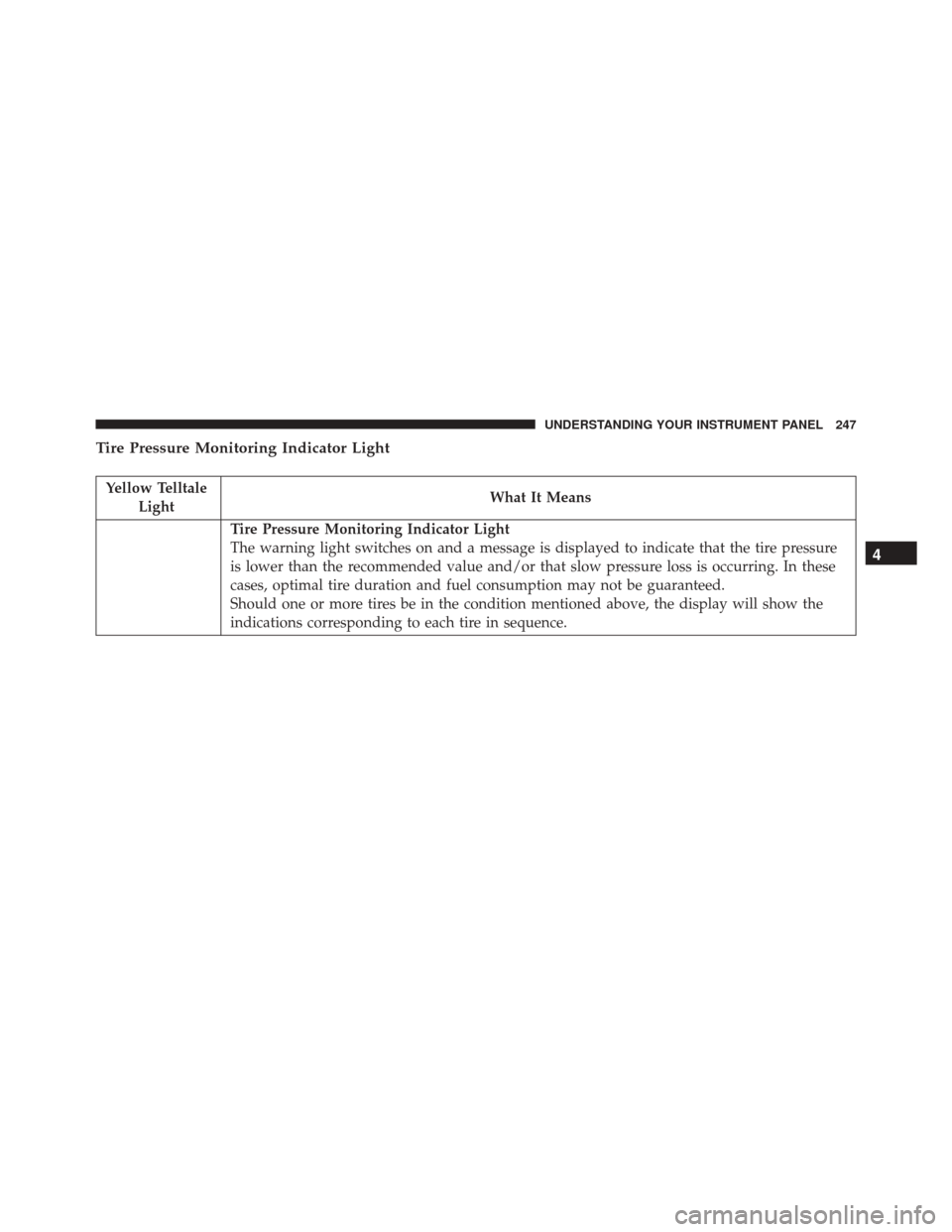
Tire Pressure Monitoring Indicator Light
Yellow TelltaleLight What It Means
Tire Pressure Monitoring Indicator Light
The warning light switches on and a message is displayed to indicate that the tire pressure
is lower than the recommended value and/or that slow pressure loss is occurring. In these
cases, optimal tire duration and fuel consumption may not be guaranteed.
Should one or more tires be in the condition mentioned above, the display will show the
indications corresponding to each tire in sequence.
4
UNDERSTANDING YOUR INSTRUMENT PANEL 247
Page 250 of 651
IMPORTANT:Do not continue driving with one or more
flat tires as handling may be compromised. Stop the
vehicle, avoiding sharp braking and steering. Repair
immediately using the dedicated tire repair kit and
contact your authorized dealership as soon as possible.
Each tire, including the spare (if provided), should be
checked monthly when cold and inflated to the inflation
pressure recommended by the vehicle manufacturer on
the vehicle placard or tire inflation pressure label. If your
vehicle has tires of a different size than the size indicated
on the vehicle placard or tire inflation pressure label, you
should determine the proper tire inflation pressure for
those tires.
As an added safety feature, your vehicle has been
equipped with a Tire Pressure Monitoring System
(TPMS) that illuminates a low tire pressure telltale when
one or more of your tires is significantly under-inflated. Accordingly, when the low tire pressure telltale illumi-
nates, you should stop and check your tires as soon as
possible and inflate them to the proper pressure. Driving
on a significantly under-inflated tire causes the tire to
overheat and can lead to tire failure. Under-inflation also
reduces fuel efficiency and tire tread life, and may affect
the vehicle’s handling and stopping ability.
Please note that the TPMS is not a substitute for proper
tire maintenance, and it is the driver ’s responsibility to
maintain correct tire pressure, even if under-inflation has
not reached the level to trigger illumination of the TPMS
low tire pressure telltale.
Your vehicle has also been equipped with a TPMS
malfunction indicator to indicate when the system is not
operating properly. The TPMS malfunction indicator is
combined with the low tire pressure telltale. When the
system detects a malfunction, the telltale will flash for
approximately one minute and then remain continuously
248 UNDERSTANDING YOUR INSTRUMENT PANEL
Page 264 of 651
the shift up indicator is shown on the display, the PSI is
advising the driver to engage a higher gear.
The PSI indicator in the DID display remains illuminated
until the driver changes gear, or the driving conditions
return to a situation where changing gear is not required,
corresponding to the configured RPMs in the head unit.
NOTE:Refer to “Uconnect Settings” in “Understanding
Your Instrument Panel” for further information on en-
abling, disabling, and configuring the Performance Shift
Indicator.
Cruise Control
This area will show reconfigurable white caution tell-
tales. These telltales include:
• Cruise Ready
This telltale will illuminate white to indicate
that the Cruise Control system is activated. •
Electronic Speed Control SET
This telltale will illuminate green when the
electronic speed control is SET. Refer to “Elec-
tronic Speed Control” in “Understanding The
Features Of Your Vehicle” for further
information.
DID Selectable Menu Items
Push and release the UPorDOWNarrow but-
tons until the desired Selectable Menu item is dis-
played in the DID.
Follow the Menu or submenu prompts as desired.
Speedometer
Push and release the UPorDOWN arrow button until
the Speedometer menu is displayed in the DID. Push and
release the OKbutton to toggle units (km/h or mph) of
the digital speedometer
262 UNDERSTANDING YOUR INSTRUMENT PANEL
Page 272 of 651
•System Cancel
• Driver Override
• System Off
• ACC Proximity Warning
• ACC Unavailable Warning
• The DID will return to the last display selected after
five seconds of no ACC display activity.
For further information, refer to “Adaptive Cruise Con-
trol (ACC) — If Equipped” in “Understanding The
Features Of Your Vehicle.”
Fuel Economy
Push and release the UPorDOWNarrow button
until the Fuel Economy Menu item is displayed in the
DID.
• Two submenu pages one with Current value (instan-
taneous calculation of the fuel economy) displayed
and one without the Current Value displayed (toggle
left or right to select one):
– Current Fuel Economy (MPG, L/100 km, or km/l)
– Range To Empty (miles or km)
– Average Fuel Economy (MPG, L/100 km, or km/l)
– The Max and Min values will correspond to the particular engine requirements
• Lower end of gauge will be displayed in an amber
color and turn green as Fuel Economy improves.
• Hold the OKbutton to reset average fuel economy
information.
Trip Info
Push and release the UPorDOWNarrow button
until the Trip Menu item is displayed in the EVIC.
270 UNDERSTANDING YOUR INSTRUMENT PANEL
Page 283 of 651
When making a selection, press the button on the touch-
screen to enter the desired mode. Once in the desired
mode, select the preferred setting option. Once the set-
ting is complete, either press the Back Arrow/Done
button on the touchscreen or the Back button on the
faceplate to return to the previous menu or press the “X”
button on the touchscreen to close out of the settings
screen. Pressing the Up or Down Arrow buttons on the
right side of the screen will allow you to toggle up or
down through the available settings.
Display
After pressing the “Display” button on the touchscreen
the following settings will be available:
•Display Mode
When in this display you may select the Auto or Manual
display settings. To change Mode status, press and re-
lease the “Auto” or “Manual” button on the touchscreen. •
Set Language
When in this display, you may select one of multiple
languages (English/Français/Español) for all display no-
menclature, including the trip functions and the naviga-
tion system (if equipped). Press the “Language” button
on the touchscreen and select from “English,” “Français,”
or “Español.”
• Touchscreen Beep
When in this display, you may turn on or shut off the
sound heard when a touchscreen button is pressed. To
change the Mode status, press and release the “On” or
“Off” button on the touchscreen.
Units
After pressing the “Units” button on the touchscreen you
may select each unit of measure independently displayed
4
UNDERSTANDING YOUR INSTRUMENT PANEL 281
Page 284 of 651
in the Driver Information Display (DID), and navigation
system (if equipped). The following selectable units of
measure are listed below:
•Speed
Select from: “MPH” or “km/h.”
• Distance
Select from: “mi” or “km.”
• Fuel Consumption
Select from: “MPG” (US), “MPG” (UK), “L/100 km” or
“km/L.”
• Pressure
Select from: “psi,” “kPa,” or “bar.”
• Temperature
Select from: “°C,” or “°F.” •
Power
Select from: “HP” (US), “HP” (UK), and “kW.”
• Torque
Select from: “lb-ft” or “Nm.”
Voice
After pressing the “Voice” button on the touchscreen the
following settings will be available:
• Voice Response Length
When in this display, you may change the Voice Re-
sponse Length settings. To change mode status, press and
release the “Brief” or “Long” button on the touchscreen.
282 UNDERSTANDING YOUR INSTRUMENT PANEL