transmission DODGE CHALLENGER 2016 3.G Owner's Manual
[x] Cancel search | Manufacturer: DODGE, Model Year: 2016, Model line: CHALLENGER, Model: DODGE CHALLENGER 2016 3.GPages: 651, PDF Size: 4.47 MB
Page 304 of 651

NOTE:If your vehicle has experienced any damage in
the area where the sensor is located, even if the fascia is
not damaged, the sensor may have become misaligned.
Take your vehicle to an authorized dealer to verify sensor
alignment. Having a sensor that is misaligned will result
in the BSM not operating to specification.
• ParkView Backup Camera Active Guidelines
Your vehicle may be equipped with the ParkView Rear
Back Up Camera Active Guidelines that allows you to see
active guidelines over the ParkView Back up camera
display whenever the shift lever is put into REVERSE.
The image will be displayed on the radio touchscreen
display along with a caution note to “check entire sur-
roundings” across the top of the screen. After five sec-
onds, this note will disappear. To make your selection,
press the “ParkView Backup Camera Active Guidelines” button on the touchscreen, until a check-mark appears
next to setting, indicating that the setting had been
selected.
•
ParkView Backup Camera Delay
When the vehicle is shifted out of REVERSE (with camera
delay turned OFF), the rear camera mode is exited and
the navigation or audio screen appears again. When the
vehicle is shifted out of REVERSE (with camera delay
turned ON), the rear view image with dynamic grid lines
will be displayed for up to 10 seconds after shifting out of
“REVERSE” unless the forward vehicle speed exceeds
8 mph (12 km/h), the transmission is shifted into
“PARK” or the ignition is switched to the OFF position.
To set the ParkView Backup Camera Delay press the
“Controls” button on the touchscreen, the “settings”
button on the touchscreen, then the “Safety & Driving
Assistance” button on the touchscreen. Press the
302 UNDERSTANDING YOUR INSTRUMENT PANEL
Page 307 of 651
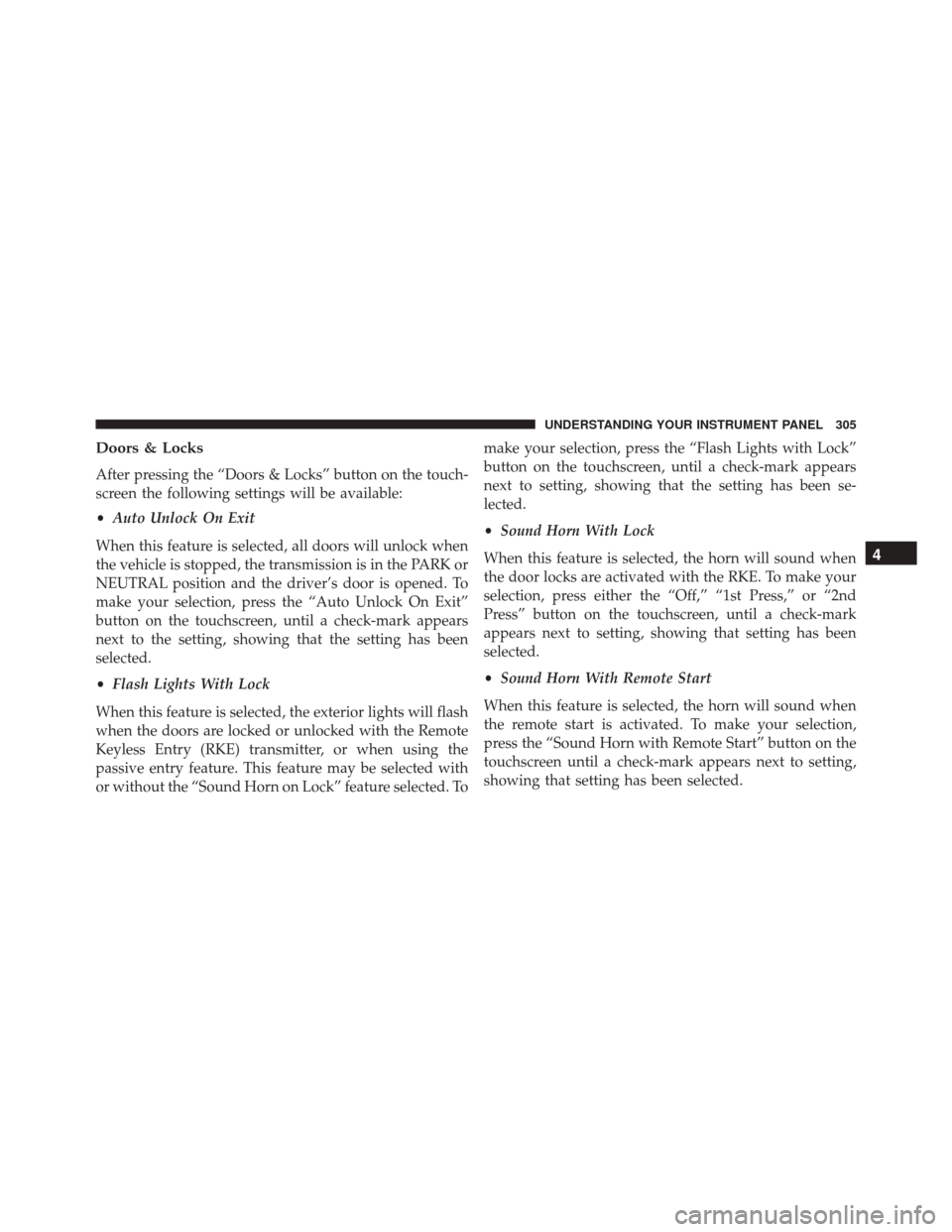
Doors & Locks
After pressing the “Doors & Locks” button on the touch-
screen the following settings will be available:
•Auto Unlock On Exit
When this feature is selected, all doors will unlock when
the vehicle is stopped, the transmission is in the PARK or
NEUTRAL position and the driver’s door is opened. To
make your selection, press the “Auto Unlock On Exit”
button on the touchscreen, until a check-mark appears
next to the setting, showing that the setting has been
selected.
• Flash Lights With Lock
When this feature is selected, the exterior lights will flash
when the doors are locked or unlocked with the Remote
Keyless Entry (RKE) transmitter, or when using the
passive entry feature. This feature may be selected with
or without the “Sound Horn on Lock” feature selected. To make your selection, press the “Flash Lights with Lock”
button on the touchscreen, until a check-mark appears
next to setting, showing that the setting has been se-
lected.
•
Sound Horn With Lock
When this feature is selected, the horn will sound when
the door locks are activated with the RKE. To make your
selection, press either the “Off,” “1st Press,” or “2nd
Press” button on the touchscreen, until a check-mark
appears next to setting, showing that setting has been
selected.
• Sound Horn With Remote Start
When this feature is selected, the horn will sound when
the remote start is activated. To make your selection,
press the “Sound Horn with Remote Start” button on the
touchscreen until a check-mark appears next to setting,
showing that setting has been selected.
4
UNDERSTANDING YOUR INSTRUMENT PANEL 305
Page 320 of 651

Gauges 2
When selected, this screen displays the following values:
•Battery Voltage
Shows the actual battery voltage.
Performance Pages — Gauges 2 (Automatic Transmission)
Performance Pages — Gauges 2 (Manual Transmission)
318 UNDERSTANDING YOUR INSTRUMENT PANEL
Page 321 of 651
•Intake Air Temperature
Shows the actual intake air temperature.
• Transmission Temperature (Automatic Transmission
Only)
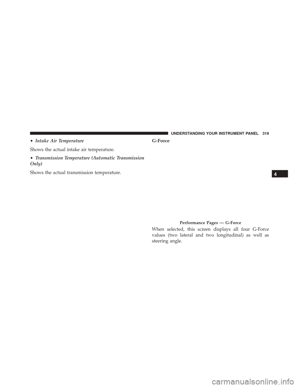
Shows the actual transmission temperature.G-Force
When selected, this screen displays all four G-Force
values (two lateral and two longitudinal) as well as
steering angle.
Performance Pages — G-Force
4
UNDERSTANDING YOUR INSTRUMENT PANEL 319
Page 323 of 651
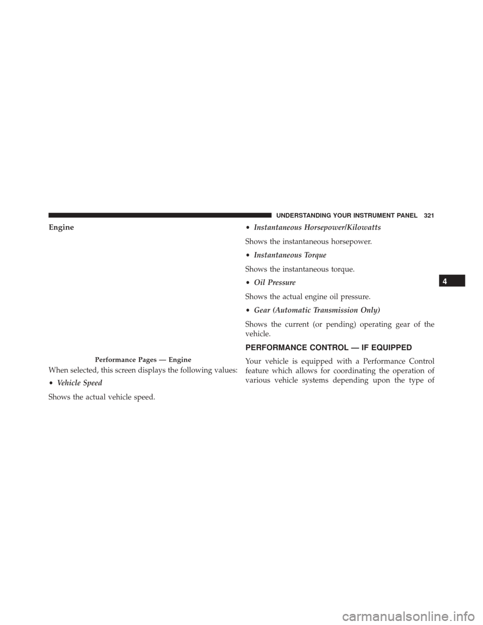
Engine
When selected, this screen displays the following values:
•Vehicle Speed
Shows the actual vehicle speed. •
Instantaneous Horsepower/Kilowatts
Shows the instantaneous horsepower.
• Instantaneous Torque
Shows the instantaneous torque.
• Oil Pressure
Shows the actual engine oil pressure.
• Gear (Automatic Transmission Only)
Shows the current (or pending) operating gear of the
vehicle.
PERFORMANCE CONTROL — IF EQUIPPED
Your vehicle is equipped with a Performance Control
feature which allows for coordinating the operation of
various vehicle systems depending upon the type ofPerformance Pages — Engine
4
UNDERSTANDING YOUR INSTRUMENT PANEL 321
Page 325 of 651
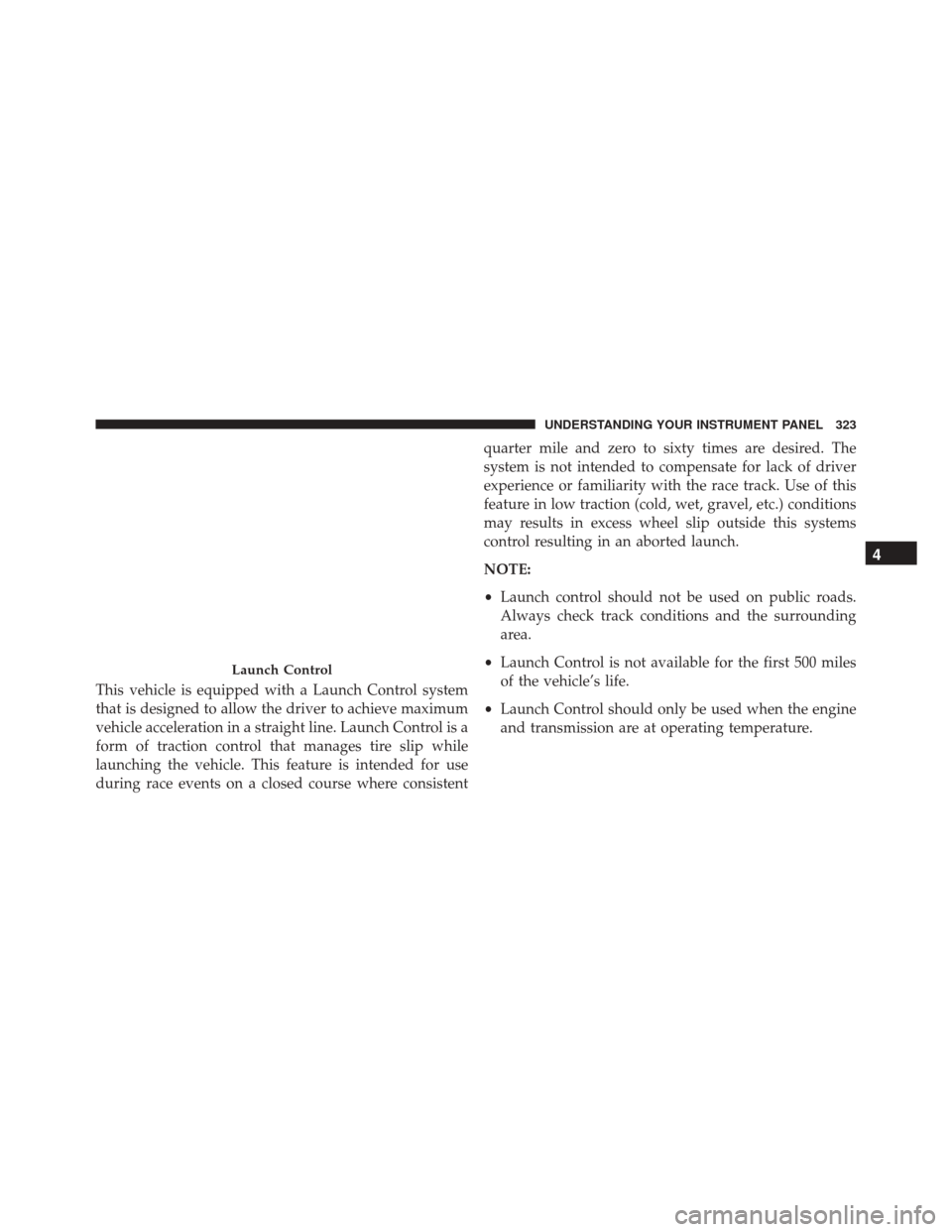
This vehicle is equipped with a Launch Control system
that is designed to allow the driver to achieve maximum
vehicle acceleration in a straight line. Launch Control is a
form of traction control that manages tire slip while
launching the vehicle. This feature is intended for use
during race events on a closed course where consistentquarter mile and zero to sixty times are desired. The
system is not intended to compensate for lack of driver
experience or familiarity with the race track. Use of this
feature in low traction (cold, wet, gravel, etc.) conditions
may results in excess wheel slip outside this systems
control resulting in an aborted launch.
NOTE:
•
Launch control should not be used on public roads.
Always check track conditions and the surrounding
area.
• Launch Control is not available for the first 500 miles
of the vehicle’s life.
• Launch Control should only be used when the engine
and transmission are at operating temperature.
Launch Control
4
UNDERSTANDING YOUR INSTRUMENT PANEL 323
Page 326 of 651
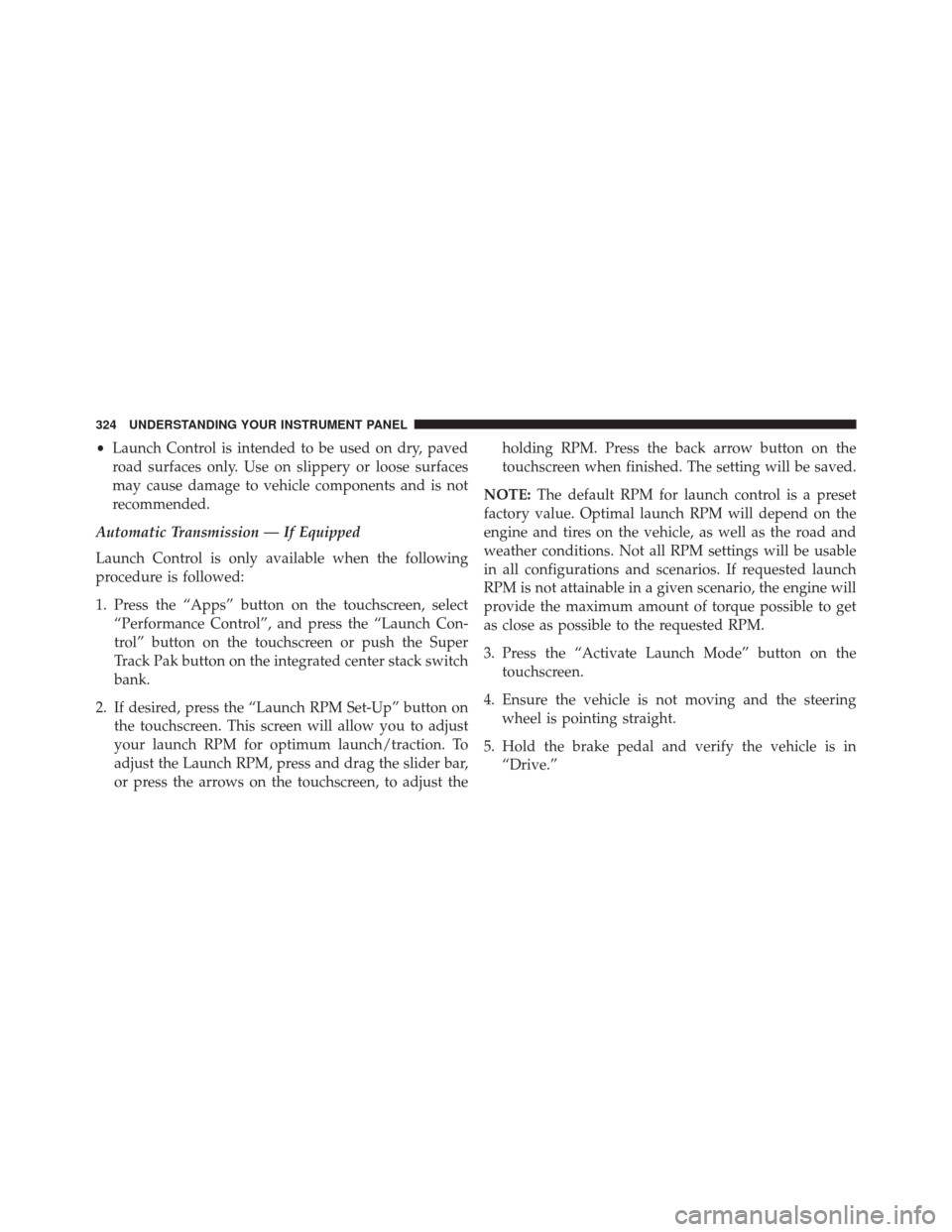
•Launch Control is intended to be used on dry, paved
road surfaces only. Use on slippery or loose surfaces
may cause damage to vehicle components and is not
recommended.
Automatic Transmission — If Equipped
Launch Control is only available when the following
procedure is followed:
1. Press the “Apps” button on the touchscreen, select “Performance Control”, and press the “Launch Con-
trol” button on the touchscreen or push the Super
Track Pak button on the integrated center stack switch
bank.
2. If desired, press the “Launch RPM Set-Up” button on the touchscreen. This screen will allow you to adjust
your launch RPM for optimum launch/traction. To
adjust the Launch RPM, press and drag the slider bar,
or press the arrows on the touchscreen, to adjust the holding RPM. Press the back arrow button on the
touchscreen when finished. The setting will be saved.
NOTE: The default RPM for launch control is a preset
factory value. Optimal launch RPM will depend on the
engine and tires on the vehicle, as well as the road and
weather conditions. Not all RPM settings will be usable
in all configurations and scenarios. If requested launch
RPM is not attainable in a given scenario, the engine will
provide the maximum amount of torque possible to get
as close as possible to the requested RPM.
3. Press the “Activate Launch Mode” button on the touchscreen.
4. Ensure the vehicle is not moving and the steering wheel is pointing straight.
5. Hold the brake pedal and verify the vehicle is in “Drive.”
324 UNDERSTANDING YOUR INSTRUMENT PANEL
Page 328 of 651
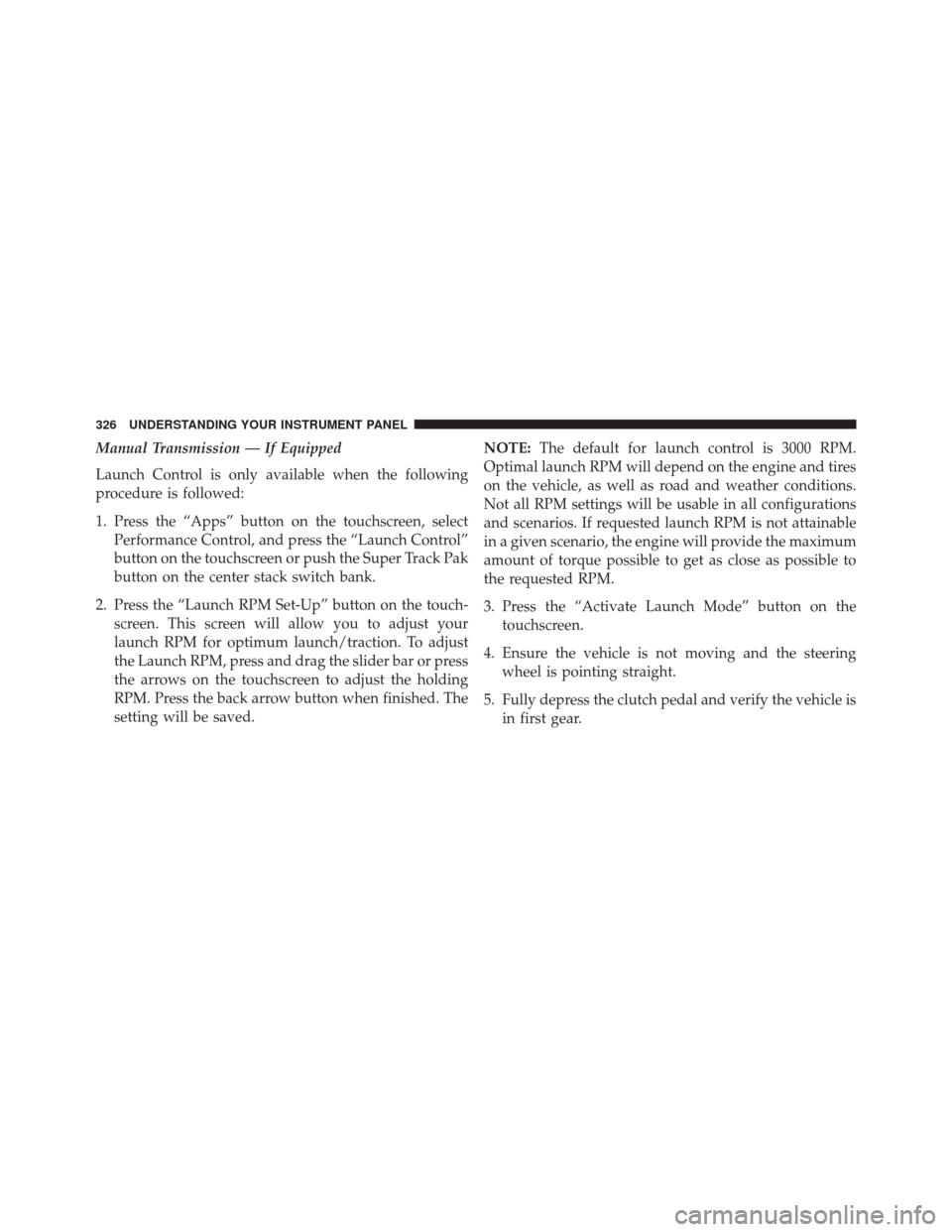
Manual Transmission — If Equipped
Launch Control is only available when the following
procedure is followed:
1. Press the “Apps” button on the touchscreen, selectPerformance Control, and press the “Launch Control”
button on the touchscreen or push the Super Track Pak
button on the center stack switch bank.
2. Press the “Launch RPM Set-Up” button on the touch- screen. This screen will allow you to adjust your
launch RPM for optimum launch/traction. To adjust
the Launch RPM, press and drag the slider bar or press
the arrows on the touchscreen to adjust the holding
RPM. Press the back arrow button when finished. The
setting will be saved. NOTE:
The default for launch control is 3000 RPM.
Optimal launch RPM will depend on the engine and tires
on the vehicle, as well as road and weather conditions.
Not all RPM settings will be usable in all configurations
and scenarios. If requested launch RPM is not attainable
in a given scenario, the engine will provide the maximum
amount of torque possible to get as close as possible to
the requested RPM.
3. Press the “Activate Launch Mode” button on the touchscreen.
4. Ensure the vehicle is not moving and the steering wheel is pointing straight.
5. Fully depress the clutch pedal and verify the vehicle is in first gear.
326 UNDERSTANDING YOUR INSTRUMENT PANEL
Page 329 of 651
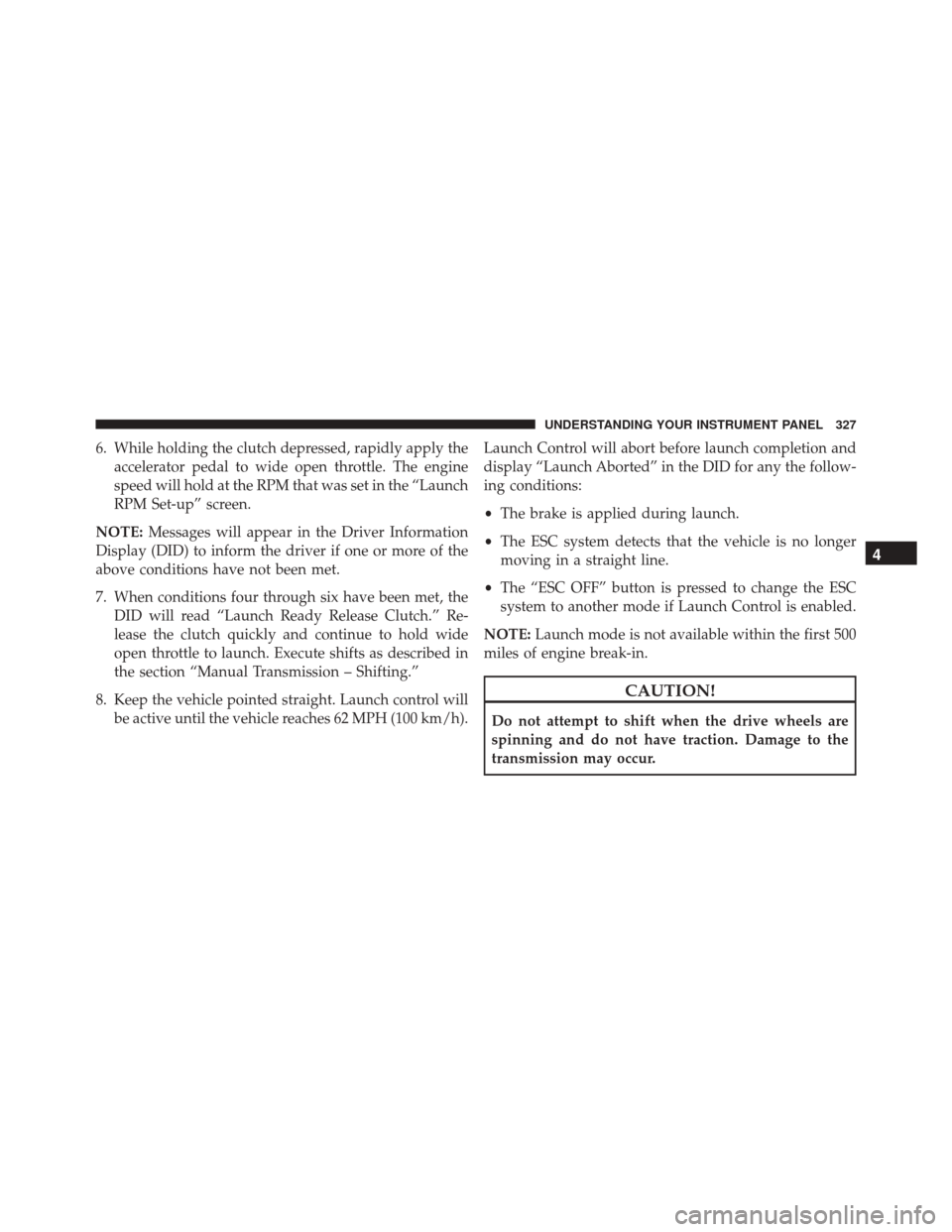
6. While holding the clutch depressed, rapidly apply theaccelerator pedal to wide open throttle. The engine
speed will hold at the RPM that was set in the “Launch
RPM Set-up” screen.
NOTE: Messages will appear in the Driver Information
Display (DID) to inform the driver if one or more of the
above conditions have not been met.
7. When conditions four through six have been met, the DID will read “Launch Ready Release Clutch.” Re-
lease the clutch quickly and continue to hold wide
open throttle to launch. Execute shifts as described in
the section “Manual Transmission – Shifting.”
8. Keep the vehicle pointed straight. Launch control will be active until the vehicle reaches 62 MPH (100 km/h). Launch Control will abort before launch completion and
display “Launch Aborted” in the DID for any the follow-
ing conditions:
•
The brake is applied during launch.
• The ESC system detects that the vehicle is no longer
moving in a straight line.
• The “ESC OFF” button is pressed to change the ESC
system to another mode if Launch Control is enabled.
NOTE: Launch mode is not available within the first 500
miles of engine break-in.
CAUTION!
Do not attempt to shift when the drive wheels are
spinning and do not have traction. Damage to the
transmission may occur.
4
UNDERSTANDING YOUR INSTRUMENT PANEL 327
Page 330 of 651
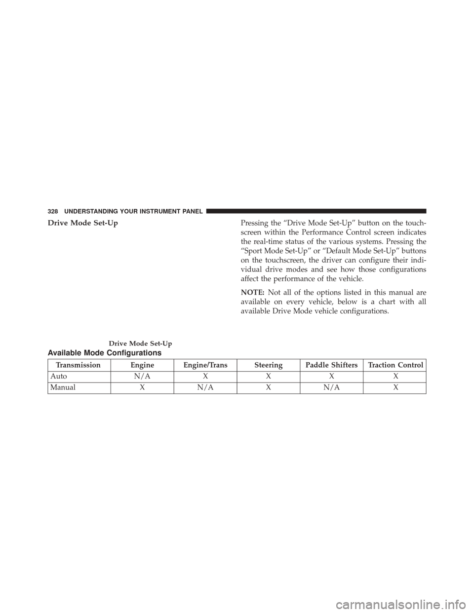
Drive Mode Set-UpPressing the “Drive Mode Set-Up” button on the touch-
screen within the Performance Control screen indicates
the real-time status of the various systems. Pressing the
“Sport Mode Set-Up” or “Default Mode Set-Up” buttons
on the touchscreen, the driver can configure their indi-
vidual drive modes and see how those configurations
affect the performance of the vehicle.
NOTE:Not all of the options listed in this manual are
available on every vehicle, below is a chart with all
available Drive Mode vehicle configurations.
Available Mode Configurations
Transmission Engine Engine/Trans Steering Paddle Shifters Traction Control
Auto N/AXXX X
Manual XN/A XN/A X
Drive Mode Set-Up
328 UNDERSTANDING YOUR INSTRUMENT PANEL