air condition DODGE CHALLENGER 2017 3.G Owners Manual
[x] Cancel search | Manufacturer: DODGE, Model Year: 2017, Model line: CHALLENGER, Model: DODGE CHALLENGER 2017 3.GPages: 506, PDF Size: 4.44 MB
Page 37 of 506
pets be restrained in the rear seat (if equipped) in pet
harnesses or pet carriers that are secured by seat belts, and
cargo is properly stowed.
BeltAlert can be activated or deactivated by your autho-
rized dealer. FCA US LLC does not recommend deactivat-
ing BeltAlert.
NOTE:If BeltAlert has been deactivated and the driver or
outboard front seat passenger (if equipped with outboard
front passenger seat BeltAlert) is unbuckled the Seat Belt
Reminder Light will turn on and remain on until the driver
and outboard front seat passenger seat belts are buckled.
Lap/Shoulder Belts
All seating positions in your vehicle are equipped with
lap/shoulder belts.
The seat belt webbing retractor will lock only during very
sudden stops or collisions. This feature allows the shoulder
part of the seat belt to move freely with you under normal
conditions. However, in a collision the seat belt will lock
and reduce your risk of striking the inside of the vehicle or
being thrown out of the vehicle.
WARNING!
• Relying on the air bags alone could lead to more
severe injuries in a collision. The air bags work with
your seat belt to restrain you properly. In some
collisions, the air bags won’t deploy at all. Always
wear your seat belt even though you have air bags.
• In a collision, you and your passengers can suffer
much greater injuries if you are not properly buckled
up. You can strike the interior of your vehicle or
other passengers, or you can be thrown out of the
vehicle. Always be sure you and others in your
vehicle are buckled up properly.
•
It is dangerous to ride in a cargo area, inside or outside
of a vehicle. In a collision, people riding in these areas
are more likely to be seriously injured or killed.
• Do not allow people to ride in any area of your
vehicle that is not equipped with seats and seat belts.
• Be sure everyone in your vehicle is in a seat and
using a seat belt properly. Occupants, including the
driver, should always wear their seat belts whether
or not an air bag is also provided at their seating
position to minimize the risk of severe injury or
death in the event of a crash.
(Continued)
2
THINGS TO KNOW BEFORE STARTING YOUR VEHICLE 35
Page 46 of 506
NOTE:If the speedometer, tachometer, or any engine
related gauges are not working, the Occupant Restraint
Controller (ORC) may also be disabled. In this condition
the air bags may not be ready to inflate for your protection.
Have an authorized dealer service the air bag system
immediately.
WARNING!
Ignoring the Air Bag Warning Light in your instrument
panel could mean you won’t have the air bag system to
protect you in a collision. If the light does not come on
as a bulb check when the ignition is first turned on,
stays on after you start the vehicle, or if it comes on as
you drive, have an authorized dealer service the air bag
system immediately.
Redundant Air Bag Warning Light
If a fault with the Air Bag Warning Light is detected, which could affect the Supplemental Restraint System
(SRS), the Redundant Air Bag Warning Light will
illuminate on the instrument panel. The Redun-
dant Air Bag Warning Light will stay on until the
fault is cleared. In addition, a single chime will sound to
alert you that the Redundant Air Bag Warning Light has
come on and a fault has been detected. If the Redundant Air Bag Warning Light comes on intermittently or remains
on while driving have an authorized dealer service the
vehicle immediately. For additional information regarding
the Redundant Air Bag Warning Light, refer to the “Un-
derstanding Your Instrument Panel” section of this
manual.
Front Air Bags
This vehicle has front air bags and lap/shoulder belts for
both the driver and front passenger. The front air bags are
a supplement to the seat belt restraint systems. The driver
front air bag is mounted in the center of the steering wheel.
The passenger front air bag is mounted in the instrument
panel, above the glove compartment. The words “SRS
AIRBAG” or “AIRBAG” are embossed on the air bag
covers.
44 THINGS TO KNOW BEFORE STARTING YOUR VEHICLE
Page 74 of 506
the passenger compartment. In addition, inspect the ex-
haust system each time the vehicle is raised for lubrication
or oil change. Replace as required.
Safety Checks You Should Make Inside The Vehicle
Seat Belts
Inspect the seat belt system periodically, checking for cuts,
frays, and loose parts. Damaged parts must be replaced
immediately. Do not disassemble or modify the system.
Front seat belt assemblies must be replaced after a collision.
Rear seat belt assemblies must be replaced after a collision
if they have been damaged (i.e., bent retractor, torn web-
bing, etc.). If there is any question regarding seat belt or
retractor condition, replace the seat belt.
Air Bag Warning Light
The Air Bag Warning Lightwill turn on for four to
eight seconds as a bulb check when the ignition is first
placed in the ON/RUN position. If the light is either not
on during starting, stays on, or turns on while driving,
have the system inspected at an authorized dealer as
soon as possible. This light will illuminate with a single
chime when a fault with the Air Bag Warning Light has
been detected, it will stay on until the fault is cleared. If
the light comes on intermittently or remains on while driving, have an authorized dealer service the vehicle
immediately. Refer to “Occupant Restraints” for further
information.
Defroster
Check operation by selecting the defrost mode and place
the blower control on high speed. You should be able to
feel the air directed against the windshield. See your
authorized dealer for service if your defroster is inoper-
able.
Floor Mat Safety Information
Always use floor mats designed to fit the footwell of your
vehicle. Use only floor mats that leave the pedal area
unobstructed and that are firmly secured so that they
cannot slip out of position and interfere with the pedals or
impair safe operation of your vehicle in other ways.
72 THINGS TO KNOW BEFORE STARTING YOUR VEHICLE
Page 175 of 506
Instrument Cluster Descriptions
1. Tachometer•Indicates the engine speed in revolutions per minute
(RPM x 1000).
2. Instrument Cluster Display •When the appropriate conditions exist, this display
shows the instrument cluster display messages. Refer
to “Instrument Cluster Display” in “Understanding
Your Instrument Panel” for further information.
3. Speedometer •Indicates vehicle speed.
4. Fuel Gauge •The pointer shows the level of fuel in the fuel tank
when the Keyless Push Button Ignition is in the
ON/RUN position.
•
The fuel pump symbol points to the side of the
vehicle where the fuel door is located.
5. Temperature Gauge
•The temperature gauge shows engine coolant tem-
perature. Any reading within the normal range indi-
cates that the engine cooling system is operating
satisfactorily. •
The gauge pointer will likely indicate a higher tem-
perature when driving in hot weather, up mountain
grades, or when towing a trailer. It should not be
allowed to exceed the upper limits of the normal
operating range.
WARNING!
A hot engine cooling system is dangerous. You or
others could be badly burned by steam or boiling
coolant. You may want to call an authorized dealer for
service if your vehicle overheats. If you decide to look
under the hood yourself, see “Maintaining Your Ve-
hicle”. Follow the warnings under the Cooling System
Pressure Cap paragraph.
CAUTION!
Driving with a hot engine cooling system could dam-
age your vehicle. If the temperature gauge reads “H”
pull over and stop the vehicle. Idle the vehicle with the
air conditioner turned off until the pointer drops back
into the normal range. If the pointer remains on the
“H”, turn the engine off immediately and call an
authorized dealer for service.
4
UNDERSTANDING YOUR INSTRUMENT PANEL 173
Page 178 of 506
Brake Warning Light
Red TelltaleLight What It Means
English
Metric
Brake Warning Light
This light monitors various brake functions, including brake fluid level and parking brake appli-
cation. If the brake light turns on it may indicate that the parking brake is applied, that the brake
fluid level is low, or that there is a problem with the anti-lock brake system reservoir.
If the light remains on when the parking brake has been disengaged, and the fluid level is at the
full mark on the master cylinder reservoir, it indicates a possible brake hydraulic system malfunc-
tion or that a problem with the Brake Booster has been detected by the Anti-Lock Brake System
(ABS) / Electronic Stability Control (ESC) system. In this case, the light will remain on until the
condition has been corrected. If the problem is related to the Brake Booster, the ABS pump will
run when applying the brake, and a brake pedal pulsation may be felt during each stop.
NOTE:
Brake Warning Light may illuminate due to excessive wear to brake pads.
The dual brake system provides a reserve braking capacity
in the event of a failure to a portion of the hydraulic
system. A leak in either half of the dual brake system is
indicated by the Brake Warning Light, which will turn on
when the brake fluid level in the master cylinder has
dropped below a specified level.
The light will remain on until the cause is corrected. NOTE:
The light may flash momentarily during sharp
cornering maneuvers, which change fluid level conditions.
The vehicle should have service performed, and the brake
fluid level checked.
If brake failure is indicated, immediate repair is necessary.
176 UNDERSTANDING YOUR INSTRUMENT PANEL
Page 189 of 506
Tire Pressure Monitoring System (TPMS) Warning Light
Yellow TelltaleLight What It Means
Tire Pressure Monitoring System (TPMS) Warning Light
The warning light switches on and a message is displayed to indicate that the tire pressure is
lower than the recommended value and/or that slow pressure loss is occurring. In these cases,
optimal tire duration and fuel consumption may not be guaranteed.
Should one or more tires be in the condition mentioned above, the display will show the indica-
tions corresponding to each tire in sequence.
CAUTION!
Do not continue driving with one or more flat tires as
handling may be compromised. Stop the vehicle,
avoiding sharp braking and steering. Repair immedi-
ately using the dedicated tire repair kit and contact
your authorized dealer as soon as possible.
Each tire, including the spare (if provided), should be
checked monthly when cold and inflated to the inflation
pressure recommended by the vehicle manufacturer on the
vehicle placard or tire inflation pressure label. (If your
vehicle has tires of a different size than the size indicated on the vehicle placard or tire inflation pressure label, you
should determine the proper tire inflation pressure for
those tires.)
As an added safety feature, your vehicle has been
equipped with a tire pressure monitoring system (TPMS)
that illuminates a low tire pressure telltale when one or
more of your tires is significantly under-inflated. Accord-
ingly, when the low tire pressure telltale illuminates, you
should stop and check your tires as soon as possible, and
inflate them to the proper pressure. Driving on a signifi-
cantly under-inflated tire causes the tire to overheat and
can lead to tire failure. Under-inflation also reduces fuel
efficiency and tire tread life, and may affect the vehicle’s
handling and stopping ability.
4
UNDERSTANDING YOUR INSTRUMENT PANEL 187
Page 269 of 506
If you push the switch up or down twice, it plays the
second track; three times, it will play the third, etc.
RADIO OPERATION AND MOBILE DEVICES
Under certain conditions, an “on” mobile device in your
vehicle can cause erratic or noisy performance from your
radio. This condition may be lessened or eliminated by
relocating the mobile device antenna. This condition is not
harmful to the radio. If your radio performance does not
satisfactorily “clear” by the repositioning of the antenna, it
is recommended that the radio volume be turned down or
off during mobile device operation when not using
Uconnect (if equipped).
Regulatory And Safety Information
USA/CANADA
Exposure to Radio Frequency Radiation
The radiated output power of the internal wireless radio is
far below the FCC radio frequency exposure limits. Nev-
ertheless, the wireless radio will be used in such a manner
that the radio is 8 inches (20 centimeters) or further from
the human body.The internal wireless radio operates within guidelines
found in radio frequency safety standards and recommen-
dations, which reflect the consensus of the scientific com-
munity.
The radio manufacturer believes the internal wireless radio
is safe for use by consumers. The level of energy emitted is
far less than the electromagnetic energy emitted by wire-
less devices such as mobile phones. However, the use of
wireless radios may be restricted in some situations or
environments, such as aboard airplanes. If you are unsure
of restrictions, you are encouraged to ask for authorization
before turning on the wireless radio.
This device complies with Part 15 of the FCC Rules and
with Industry Canada license-exempt RSS standard(s).
Operation is subject to the following two conditions:
1. This device may not cause harmful interference.
2. This device must accept any interference received, in-
cluding interference that may cause undesired
operation.
4
UNDERSTANDING YOUR INSTRUMENT PANEL 267
Page 273 of 506
Automatic Climate Control Descriptions
NOTE:Icons and descriptions can vary based upon vehicle equipment.
Icon Description
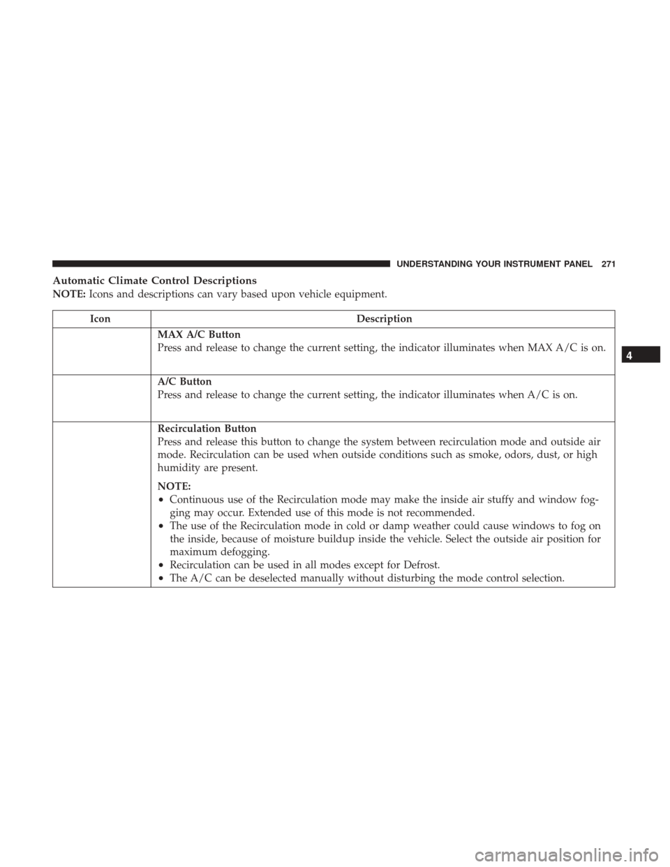
MAX A/C Button
Press and release to change the current setting, the indicator illuminates when MAX A/C is on.
A/C Button
Press and release to change the current setting, the indicator illuminates when A/C is on.
Recirculation Button
Press and release this button to change the system between recirculation mode and outside air
mode. Recirculation can be used when outside conditions such as smoke, odors, dust, or high
humidity are present.
NOTE:
•Continuous use of the Recirculation mode may make the inside air stuffy and window fog-
ging may occur. Extended use of this mode is not recommended.
•The use of the Recirculation mode in cold or damp weather could cause windows to fog on
the inside, because of moisture buildup inside the vehicle. Select the outside air position for
maximum defogging.
•Recirculation can be used in all modes except for Defrost.
•The A/C can be deselected manually without disturbing the mode control selection.
4
UNDERSTANDING YOUR INSTRUMENT PANEL 271
Page 276 of 506
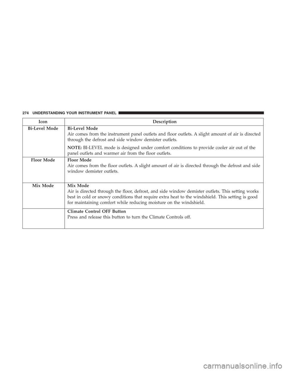
IconDescription
Bi-Level Mode
Bi-Level Mode
Air comes from the instrument panel outlets and floor outlets. A slight amount of air is directed
through the defrost and side window demister outlets.
NOTE: BI-LEVEL mode is designed under comfort conditions to provide cooler air out of the
panel outlets and warmer air from the floor outlets.
Floor Mode
Floor Mode
Air comes from the floor outlets. A slight amount of air is directed through the defrost and side
window demister outlets.
Mix Mode
Mix Mode
Air is directed through the floor, defrost, and side window demister outlets. This setting works
best in cold or snowy conditions that require extra heat to the windshield. This setting is good
for maintaining comfort while reducing moisture on the windshield.
Climate Control OFF Button
Press and release this button to turn the Climate Controls off.
274 UNDERSTANDING YOUR INSTRUMENT PANEL
Page 277 of 506
CAUTION!
Failure to follow these cautions can cause damage to
the heating elements:
•Use care when washing the inside of the rear win-
dow. Do not use abrasive window cleaners on the
interior surface of the window. Use a soft cloth and a
mild washing solution, wiping parallel to the heat-
ing elements. Labels can be peeled off after soaking
with warm water.
• Do not use scrapers, sharp instruments, or abrasive
window cleaners on the interior surface of the win-
dow.
• Keep all objects a safe distance from the window.
Climate Control Functions
A/C (Air Conditioning)
The Air Conditioning (A/C) button allows the operator to
manually activate or deactivate the air conditioning sys-
tem. When the air conditioning system is turned on, cool
dehumidified air will flow through the outlets into the
cabin. For improved fuel economy, press the A/C button to
turn off the air conditioning and manually adjust the
blower and airflow mode settings. Also, make sure to select
only Panel, Bi-Level or Floor modes. NOTE:
•
For Manual Climate Controls, if the system is in Mix,
Floor or Defrost Mode, the A/C can be turned off, but
the A/C system shall remain active to prevent fogging of
the windows.
• If fog or mist appears on the windshield or side glass,
select Defrost mode and adjust blower speed if needed.
• If your air conditioning performance seems lower than
expected, check the front of the A/C condenser (located
in front of the radiator), for an accumulation of dirt or
insects. Clean with a gentle water spray from the front of
the radiator and through the condenser.
MAX A/C
MAX A/C sets the control for maximum cooling perfor-
mance.
Press and release to toggle between MAX A/C and the
prior settings. The button illuminates when MAX A/C is
on.
In MAX A/C, the blower level and mode position can be
adjusted to desired user settings. Pressing other settings
will cause the MAX A/C operation to switch to the selected
setting and MAX A/C to exit.
4
UNDERSTANDING YOUR INSTRUMENT PANEL 275