brakes DODGE CHALLENGER 2018 Owners Manual
[x] Cancel search | Manufacturer: DODGE, Model Year: 2018, Model line: CHALLENGER, Model: DODGE CHALLENGER 2018Pages: 516, PDF Size: 5.17 MB
Page 124 of 516
SAFETY FEATURES
Anti-Lock Brake System (ABS)
The Anti-Lock Brake System (ABS) provides increased
vehicle stability and brake performance under most brak-
ing conditions. The system automatically prevents wheel
lock, and enhances vehicle control during braking.
The ABS performs a self-check cycle to ensure that the ABS
is working properly each time the vehicle is started and
driven. During this self-check, you may hear a slight
clicking sound as well as some related motor noises.
ABS is activated during braking when the system detects
one or more wheels begin to lock. Road conditions such as
ice, snow, gravel, bumps, railroad tracks, loose debris, or
panic stops may increase the likelihood of ABS activa-
tion(s).
You also may experience the following when ABS activates:
•The ABS motor noise (it may continue to run for a short
time after the stop).
• The clicking sound of solenoid valves.
• Brake pedal pulsations.
• A slight drop of the brake pedal at the end of the stop. These are all normal characteristics of ABS.
WARNING!
•
The ABS contains sophisticated electronic equip-
ment that may be susceptible to interference caused
by improperly installed or high output radio trans-
mitting equipment. This interference can cause pos-
sible loss of anti-lock braking capability. Installation
of such equipment should be performed by qualified
professionals.
• Pumping of the Anti-Lock Brakes will diminish their
effectiveness and may lead to a collision. Pumping
makes the stopping distance longer. Just press firmly
on your brake pedal when you need to slow down or
stop.
• The ABS cannot prevent the natural laws of physics
from acting on the vehicle, nor can it increase brak-
ing or steering efficiency beyond that afforded by the
condition of the vehicle brakes and tires or the
traction afforded.
• The ABS cannot prevent collisions, including those
resulting from excessive speed in turns, following
another vehicle too closely, or hydroplaning.
(Continued)
122 SAFETY
Page 125 of 516
WARNING!(Continued)
•The capabilities of an ABS equipped vehicle must
never be exploited in a reckless or dangerous manner
that could jeopardize the user ’s safety or the safety of
others.
ABS is designed to function with the OEM tires. Modifica-
tion may result in degraded ABS performance.
Anti-Lock Brake Warning Light
The yellow “Anti-Lock Brake Warning Light” will turn on
when the ignition is turned to the ON/RUN mode and
may stay on for as long as four seconds.
If the “Anti-Lock Brake Warning Light” remains on or
comes on while driving, it indicates that the anti-lock
portion of the brake system is not functioning and that
service is required. However, the conventional brake sys-
tem will continue to operate normally if the “Anti-Lock
Brake Warning Light” is on.
If the “Anti-Lock Brake Warning Light” is on, the brake
system should be serviced as soon as possible to restore the benefits of anti-lock brakes. If the “Anti-Lock Brake Warn-
ing Light” does not come on when the ignition is turned to
the ON/RUN mode, have the light repaired as soon as
possible.
Electronic Brake Control System (EBC)
Your vehicle is equipped with an advanced Electronic
Brake Control system (EBC). This system includes Elec-
tronic Brake Force Distribution (EBD), Anti-Lock Brake
System (ABS), Brake Assist System (BAS), Hill Start Assist
(HSA), Traction Control System (TCS), Electronic Stability
Control (ESC), and Electronic Roll Mitigation (ERM). These
systems work together to enhance both vehicle stability
and control in various driving conditions.
Your vehicle may also be equipped with Ready Alert
Braking (RAB), and Rain Brake Support (RBS).
Brake Assist System (BAS)
The BAS is designed to optimize the vehicle’s braking
capability during emergency braking maneuvers. The sys-
tem detects an emergency braking situation by sensing the
rate and amount of brake application and then applies
optimum pressure to the brakes. This can help reduce
braking distances. The BAS complements the anti-lock
brake system (ABS). Applying the brakes very quickly
5
SAFETY 123
Page 126 of 516
results in the best BAS assistance. To receive the benefit of
the system, you must apply continuous braking pressure
during the stopping sequence, (do not “pump” the brakes).
Do not reduce brake pedal pressure unless braking is no
longer desired. Once the brake pedal is released, the BAS is
deactivated.
WARNING!
The Brake Assist System (BAS) cannot prevent the
natural laws of physics from acting on the vehicle, nor
can it increase the traction afforded by prevailing road
conditions. BAS cannot prevent collisions, including
those resulting from excessive speed in turns, driving
on very slippery surfaces, or hydroplaning. The capa-
bilities of a BAS-equipped vehicle must never be
exploited in a reckless or dangerous manner, which
could jeopardize the user’s safety or the safety of
others.
Brake System Warning Light
The red “Brake System Warning Light” will turn on when
the ignition is turned to the ON/RUN mode and may stay
on for as long as four seconds.If the “Brake System Warning Light” remains on or comes
on while driving, it indicates that the brake system is not
functioning properly and that immediate service is re-
quired. If the “Brake System Warning Light” does not come
on when the ignition is turned to the ON/RUN mode, have
the light repaired as soon as possible.
Electronic Brake Force Distribution (EBD)
This function manages the distribution of the braking
torque between the front and rear axles by limiting braking
pressure to the rear axle. This is done to prevent overslip of
the rear wheels to avoid vehicle instability, and to prevent
the rear axle from entering ABS before the front axle.
Electronic Roll Mitigation (ERM)
This system anticipates the potential for wheel lift by
monitoring the driver ’s steering wheel input and the speed
of the vehicle. When ERM determines that the rate of
change of the steering wheel angle and vehicle’s speed are
sufficient to potentially cause wheel lift, it then applies the
appropriate brake and may also reduce engine power to
lessen the chance that wheel lift will occur. ERM can only
reduce the chance of wheel lift occurring during severe or
evasive driving maneuvers; it cannot prevent wheel lift
due to other factors, such as road conditions, leaving the
roadway, or striking objects or other vehicles.
124 SAFETY
Page 132 of 516
Towing With HSA
HSA will also provide assistance to mitigate roll back while
towing a trailer.
WARNING!
•If you use a trailer brake controller with your trailer,
the trailer brakes may be activated and deactivated
with the brake switch. If so, there may not be enough
brake pressure to hold both the vehicle and the
trailer on a hill when the brake pedal is released. In
order to avoid rolling down an incline while resum-
ing acceleration, manually activate the trailer brake
or apply more vehicle brake pressure prior to releas-
ing the brake pedal.
• HSA is not a parking brake. Always apply the
parking brake fully when exiting your vehicle. Also,
be certain to place the transmission in PARK.
• Failure to follow these warnings can result in a
collision or serious personal injury.
Disabling And Enabling HSA
This feature can be turned on or turned off. To change the
current setting, proceed as follows:
• If disabling HSA using your instrument cluster display,
refer to “Instrument Cluster Display” in “Getting To
Know Your Instrument Panel” for further information.
• If disabling HSA using Uconnect Settings, refer to
“Uconnect Settings” in “Multimedia” for further infor-
mation.
For vehicles not equipped with an instrument cluster
display, perform the following steps:
1. Center the steering wheel (front wheels pointing straight forward).
2. Shift the transmission into PARK.
3. Apply the parking brake.
4. Start the engine.
5. Rotate the steering wheel slightly more than one-half turn to the left.
130 SAFETY
Page 198 of 516
STARTING THE ENGINE
Before starting your vehicle, adjust your seat, adjust the
inside and outside mirrors, fasten your seat belt, and if
present, instruct all other occupants to buckle their seat
belts.
WARNING!
•When exiting the vehicle, always make sure the
keyless ignition node is in “OFF” mode, remove the
key fob from the vehicle and lock the vehicle.
• Never leave children alone in a vehicle, or with
access to an unlocked vehicle. Leaving children in a
vehicle unattended is dangerous for a number of
reasons. A child or others could be seriously or
fatally injured. Children should be warned not to
touch the parking brake, brake pedal or the trans-
mission gear selector.
• Do not leave the key fob in or near the vehicle (or in
a location accessible to children), and do not leave
the ignition (of a vehicle equipped with Keyless
Enter-N-Go) in the ACC or ON/RUN mode. A child
could operate power windows, other controls, or
move the vehicle.
(Continued)
WARNING! (Continued)
•Do not leave children or animals inside parked
vehicles in hot weather. Interior heat build-up may
cause serious injury or death.
Manual Transmission — If Equipped
Apply the parking brake, place the gear selector in NEU-
TRAL and press the clutch pedal before starting vehicle.
This vehicle is equipped with a clutch interlocking ignition
system. It will not start unless the clutch pedal is pressed to
the floor.
Automatic Transmission — If Equipped
The gear selector must be in the PARK position before you
can start the engine. Apply the brakes before shifting into
any driving gear.
CAUTION!
Damage to the transmission may occur if the following
precautions are not observed:
• Shift into or out of PARK or REVERSE only after the
vehicle has come to a complete stop.
(Continued)
196 STARTING AND OPERATING
Page 211 of 516
CAUTION!
Damage to the transmission may occur if the following
precautions are not observed:
•Shift into or out of PARK or REVERSE only after the
vehicle has come to a complete stop.
• Do not shift between PARK, REVERSE, NEUTRAL,
or DRIVE when the engine is above idle speed.
• Before shifting into any gear, make sure your foot is
firmly pressing the brake pedal.
NOTE: You must press and hold the brake pedal while
shifting out of PARK.
Ignition Park Interlock
This vehicle is equipped with an Ignition Park Interlock
which requires the transmission to be in PARK before the
ignition can be turned to the OFF mode. This helps the
driver avoid inadvertently leaving the vehicle without
placing the transmission in PARK. This system also locks
the transmission in PARK whenever the ignition is in the
OFF mode. NOTE:
The transmission is NOT locked in PARK when the
ignition is in the ACC mode (even though the engine will
be off). Ensure that the transmission is in PARK, and the
ignition is OFF(not in ACC mode) before exiting the
vehicle.
Brake/Transmission Shift Interlock System
This vehicle is equipped with a Brake Transmission Shift
Interlock system (BTSI) that holds the transmission gear
selector in PARK unless the brakes are applied. To shift the
transmission out of PARK, the engine must be running and
the brake pedal must be pressed. The brake pedal must
also be pressed to shift from NEUTRAL into DRIVE or
REVERSE when the vehicle is stopped or moving at low
speeds.
Eight-Speed Automatic Transmission
The transmission gear range (PRNDM) is displayed both
on the gear selector and in the instrument cluster.
To select a gear range, press the lock button on the gear
selector and move the selector rearward or forward. To
shift the transmission out of PARK, the engine must be
running and the brake pedal must be pressed. You must
also press the brake pedal to shift from NEUTRAL into
6
STARTING AND OPERATING 209
Page 227 of 516
Activating Adaptive Cruise Control (ACC)
You can only engage ACC if the vehicle speed is above
20 mph (32 km/h).
The system will cancel when the vehicle speed drops below
15 mph (24 km/h).
The minimum set speed for the ACC system is 20 mph
(32 km/h).
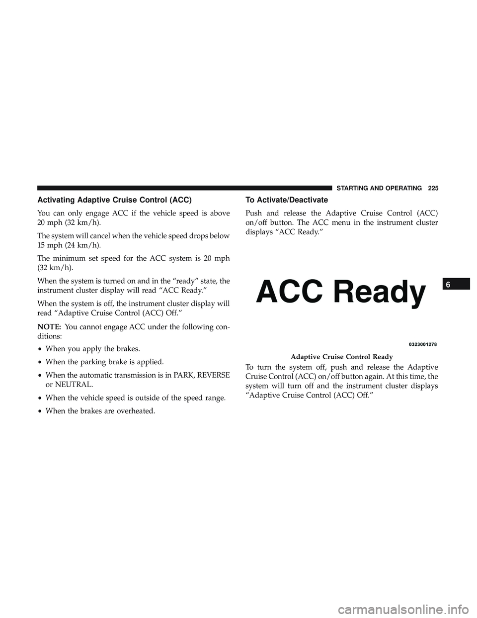
When the system is turned on and in the “ready” state, the
instrument cluster display will read “ACC Ready.”
When the system is off, the instrument cluster display will
read “Adaptive Cruise Control (ACC) Off.”
NOTE:You cannot engage ACC under the following con-
ditions:
• When you apply the brakes.
• When the parking brake is applied.
• When the automatic transmission is in PARK, REVERSE
or NEUTRAL.
• When the vehicle speed is outside of the speed range.
• When the brakes are overheated.
To Activate/Deactivate
Push and release the Adaptive Cruise Control (ACC)
on/off button. The ACC menu in the instrument cluster
displays “ACC Ready.”
To turn the system off, push and release the Adaptive
Cruise Control (ACC) on/off button again. At this time, the
system will turn off and the instrument cluster displays
“Adaptive Cruise Control (ACC) Off.”
Adaptive Cruise Control Ready
6
STARTING AND OPERATING 225
Page 233 of 516
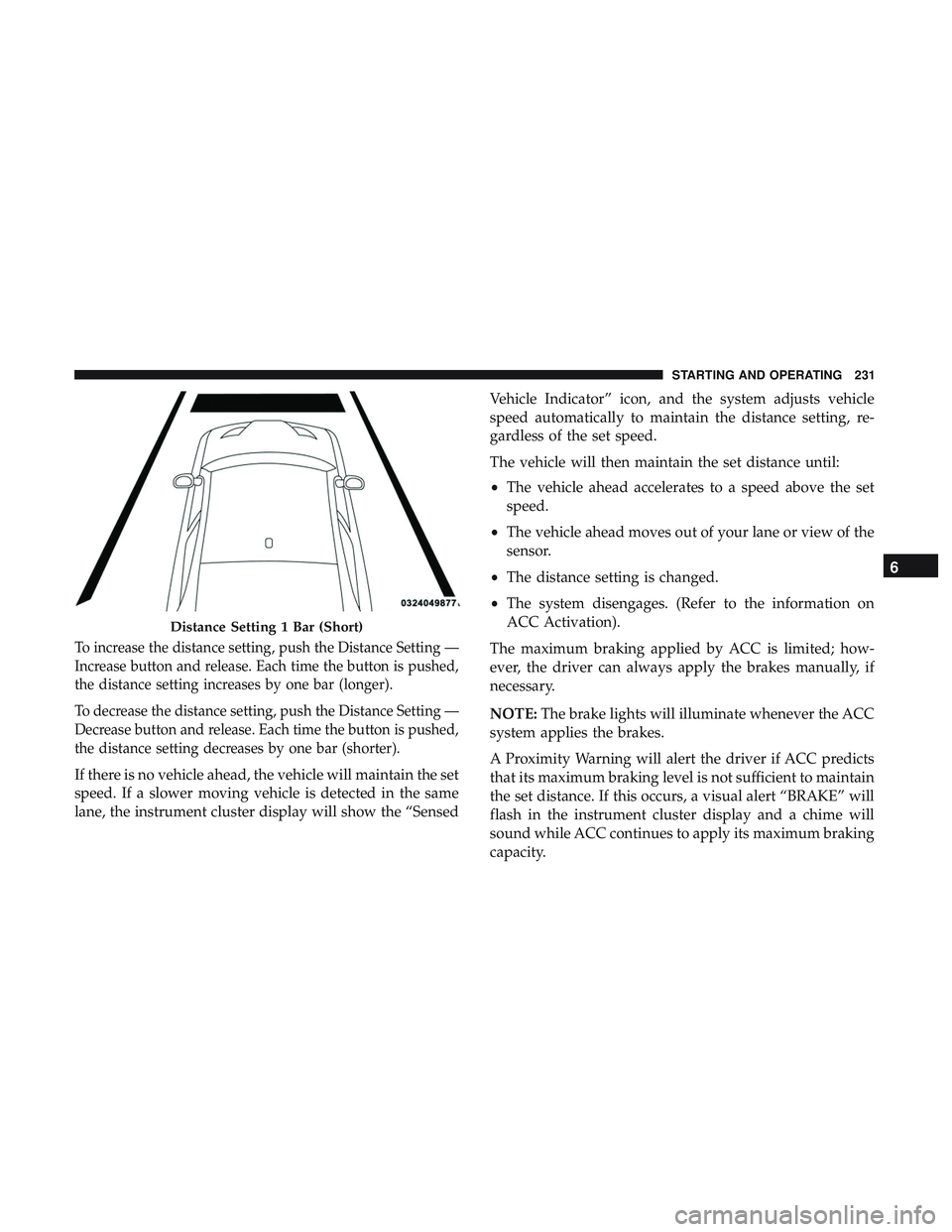
To increase the distance setting, push the Distance Setting —
Increase button and release. Each time the button is pushed,
the distance setting increases by one bar (longer).
To decrease the distance setting, push the Distance Setting —
Decrease button and release. Each time the button is pushed,
the distance setting decreases by one bar (shorter).
If there is no vehicle ahead, the vehicle will maintain the set
speed. If a slower moving vehicle is detected in the same
lane, the instrument cluster display will show the “SensedVehicle Indicator” icon, and the system adjusts vehicle
speed automatically to maintain the distance setting, re-
gardless of the set speed.
The vehicle will then maintain the set distance until:
•
The vehicle ahead accelerates to a speed above the set
speed.
• The vehicle ahead moves out of your lane or view of the
sensor.
• The distance setting is changed.
• The system disengages. (Refer to the information on
ACC Activation).
The maximum braking applied by ACC is limited; how-
ever, the driver can always apply the brakes manually, if
necessary.
NOTE: The brake lights will illuminate whenever the ACC
system applies the brakes.
A Proximity Warning will alert the driver if ACC predicts
that its maximum braking level is not sufficient to maintain
the set distance. If this occurs, a visual alert “BRAKE” will
flash in the instrument cluster display and a chime will
sound while ACC continues to apply its maximum braking
capacity.
Distance Setting 1 Bar (Short)
6
STARTING AND OPERATING 231
Page 234 of 516
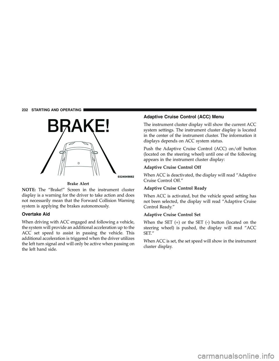
NOTE:The “Brake!” Screen in the instrument cluster
display is a warning for the driver to take action and does
not necessarily mean that the Forward Collision Warning
system is applying the brakes autonomously.
Overtake Aid
When driving with ACC engaged and following a vehicle,
the system will provide an additional acceleration up to the
ACC set speed to assist in passing the vehicle. This
additional acceleration is triggered when the driver utilizes
the left turn signal and will only be active when passing on
the left hand side.
Adaptive Cruise Control (ACC) Menu
The instrument cluster display will show the current ACC
system settings. The instrument cluster display is located
in the center of the instrument cluster. The information it
displays depends on ACC system status.
Push the Adaptive Cruise Control (ACC) on/off button
(located on the steering wheel) until one of the following
appears in the instrument cluster display:
Adaptive Cruise Control Off
When ACC is deactivated, the display will read “Adaptive
Cruise Control Off.”
Adaptive Cruise Control Ready
When ACC is activated, but the vehicle speed setting has
not been selected, the display will read “Adaptive Cruise
Control Ready.”
Adaptive Cruise Control Set
When the SET (+) or the SET (-) button (located on the
steering wheel) is pushed, the display will read “ACC
SET.”
When ACC is set, the set speed will show in the instrument
cluster display.
Brake Alert
232 STARTING AND OPERATING
Page 238 of 516
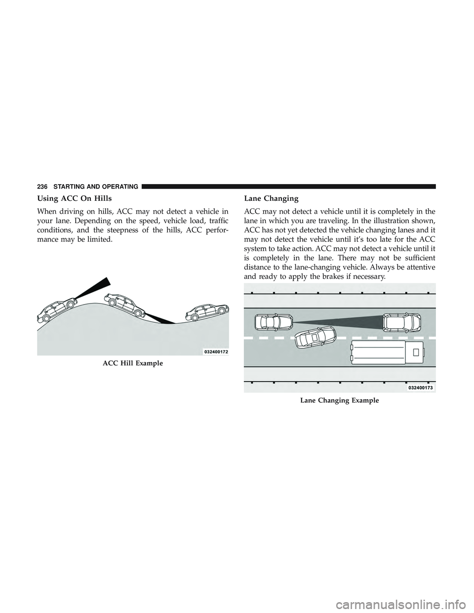
Using ACC On Hills
When driving on hills, ACC may not detect a vehicle in
your lane. Depending on the speed, vehicle load, traffic
conditions, and the steepness of the hills, ACC perfor-
mance may be limited.
Lane Changing
ACC may not detect a vehicle until it is completely in the
lane in which you are traveling. In the illustration shown,
ACC has not yet detected the vehicle changing lanes and it
may not detect the vehicle until it’s too late for the ACC
system to take action. ACC may not detect a vehicle until it
is completely in the lane. There may not be sufficient
distance to the lane-changing vehicle. Always be attentive
and ready to apply the brakes if necessary.
ACC Hill Example
Lane Changing Example
236 STARTING AND OPERATING