engine oil DODGE CHALLENGER 2020 Owners Manual
[x] Cancel search | Manufacturer: DODGE, Model Year: 2020, Model line: CHALLENGER, Model: DODGE CHALLENGER 2020Pages: 396, PDF Size: 16.64 MB
Page 5 of 396
3
INTERIOR LIGHTS .................................................43 Map/Reading Lights ................................... 43
Ambient Light — If Equipped ....................... 44
Dimmer Controls ........................................ 44
WINDSHIELD WIPERS AND WASHERS .............45
Wiper Operation ........................................... 45
Rain Sensing Wipers — If Equipped ............ 46
CLIMATE CONTROLS ...........................................47
Automatic Climate Control Overview ......... 47
Climate Control Functions ........................... 52
Automatic Temperature Control (ATC) ....... 52
Operating Tips ............................................. 53
WINDOWS ............................................................54
Power Window Controls............................... 54
Wind Buffeting ............................................ 55
POWER SUNROOF — IF EQUIPPED.....................55
Opening Sunroof .......................................... 56
Closing Sunroof ............................................ 56
Wind Buffeting ............................................ 56
Sunshade Operation.................................... 56
Pinch Protect Feature .................................. 56
Sunroof Maintenance .................................. 57
Ignition Off Operation .................................. 57
HOOD ..................................................................57
To Open The Hood .................................... 57
To Close The Hood ....................................... 57
TRUNK ................................................................58
Opening ........................................................ 58
Closing .......................................................... 58
Trunk Safety ................................................. 59 GARAGE DOOR OPENER — IF EQUIPPED ......... 59
Before You Begin Programming
HomeLink® .................................................. 59 Canadian/Gate Operator Programming ..... 61
Using HomeLink®........................................ 62
Security......................................................... 62
Troubleshooting Tips ................................... 63
General Information .................................... 63
INTERNAL EQUIPMENT ........................................ 64
Storage ......................................................... 64
Cupholders ................................................... 65
Illuminated Cupholders — If Equipped ....... 65
Electrical Power Outlets ............................ 65
GETTING TO KNOW YOUR
INSTRUMENT PANEL
INSTRUMENT CLUSTER ....................................... 68
Instrument Cluster Descriptions ................. 70
SRT INSTRUMENT CLUSTER .............................. 71
SRT Instrument Cluster Descriptions ......... 73
INSTRUMENT CLUSTER DISPLAY....................... 73
Location And Controls ................................. 74
Engine Oil Life Reset ................................. 75
Performance Shift Indicator (PSI) —
If Equipped ................................................... 76 Instrument Cluster Display Selectable
Menu Items .................................................. 76 Battery Saver On/Battery Saver Mode
Message — Electrical Load Reduction
Actions — If Equipped ............................... 81 WARNING LIGHTS AND MESSAGES ..................82
Red Warning Lights ..................................... 83
Yellow Warning Lights ................................. 86
Yellow Indicator Lights ................................ 89
Green Indicator Lights ................................. 89
White Indicator Lights ................................. 90
Blue Indicator Lights ................................... 91
ONBOARD DIAGNOSTIC SYSTEM —
OBD II ..................................................................91
Onboard Diagnostic System
(OBD II) Cybersecurity ................................. 91
EMISSIONS INSPECTION AND
MAINTENANCE PROGRAMS ...............................92
SAFETY
SAFETY FEATURES ...............................................93
Anti-Lock Brake System (ABS) ................... 93
Electronic Brake Control (EBC) System ..... 94
AUXILIARY DRIVING SYSTEMS ........................ 100
Blind Spot Monitoring (BSM) —
If Equipped ................................................. 100 Forward Collision Warning (FCW)
Operation - If Equipped ............................. 105 Tire Pressure Monitoring System
(TPMS) ........................................................ 107
20_LA_OM_EN_USC_t.book Page 3
Page 7 of 396
5
PARKVIEW REAR BACK UP CAMERA ............. 186
REFUELING THE VEHICLE ................................. 188 Loose Fuel Filler Cap Message ................. 188
VEHICLE LOADING .......................................... 189
Vehicle Certification Label .......................189
Gross Vehicle Weight Rating (GVWR) ......189Gross Axle Weight Rating (GAWR) ........... 189Overloading ................................................189
Loading ....................................................190
TRAILER TOWING ............................................. 190
Common Towing Definitions .....................190Trailer Hitch Classification ........................ 191Trailer Towing Weights (Maximum
Trailer Weight Ratings) ............................192 Trailer And Tongue Weight .......................193
Towing Requirements ................................193Towing Tips ................................................196
RECREATIONAL TOWING
(BEHIND MOTORHOME, ETC.) .......................... 197
DRIVING TIPS ..................................................... 197
Driving On Slippery Surfaces.....................197Driving Through Water .............................. 197
IN CASE OF EMERGENCY
HAZARD WARNING FLASHERS ..................... 199
ASSIST AND SOS MIRROR — IF EQUIPPED.... 199
General Information ..................................203 BULB REPLACEMENT ........................................ 204
Replacement Bulbs ................................... 204
Replacing Exterior Bulbs ........................... 206
FUSES ..................................................................207
General Information .................................. 208Underhood Fuses ...................................... 208
Rear Interior Fuses .................................... 211
JACKING AND TIRE CHANGING ........................216
Jack Location/Spare Tire Stowage .......... 216Preparations For Jacking........................... 217
Jacking And Changing A Tire .................... 217
TIRE SERVICE KIT — IF EQUIPPED ................... 220
Tire Service Kit Storage ............................. 220Tire Service Kit Components And
Operation.................................................... 221 Tire Service Kit Usage Precautions .......... 221Sealing A Tire With Tire Service Kit .......... 223
JUMP STARTING ................................................. 226
Preparations For Jump Start ..................... 227Jump Starting Procedure .......................... 227
IF YOUR ENGINE OVERHEATS .......................... 229
MANUAL PARK RELEASE — 8 – SPEED
TRANSMISSION ................................................. 229
FREEING A STUCK VEHICLE ..............................231
TOWING A DISABLED VEHICLE ........................232 Rear-Wheel Drive (RWD) Models .............. 233 ENHANCED ACCIDENT RESPONSE SYSTEM
(EARS) ................................................................ 233
EVENT DATA RECORDER (EDR) ....................... 233
SERVICING AND MAINTENANCE
SCHEDULED SERVICING .................................. 234
3.6L And 5.7L Engines ............................. 234
6.2L Supercharged And 6.4L Engines ..... 239
ENGINE COMPARTMENT .................................. 246
3.6L Engine ............................................... 246
5.7L Engine ............................................... 247
6.2L Supercharged Engine ...................... 248
6.4L Engine ............................................... 249
Checking Oil Level — 3.6L And 5.7L
Engine ........................................................ 250 Checking Oil Level — 6.2L Supercharged
Engine And 6.4L Engine ........................... 250 Adding Washer Fluid ................................. 250Maintenance-Free Battery ....................... 251Pressure Washing...................................... 251
20_LA_OM_EN_USC_t.book Page 5
Page 8 of 396
6
DEALER SERVICE .............................................. 252 Engine Oil ...................................................252
Engine Oil Filter .........................................255
Engine Air Cleaner Filter ...........................255
Air Conditioner Maintenance ....................257
Accessory Drive Belt Inspection................258Body Lubrication ........................................259
Windshield Wiper Blades ..........................259
Exhaust System .........................................261
Cooling System ........................................262
Brake System ............................................266
Clutch Hydraulic System — Manual
Transmission (If Equipped) .......................267 Manual Transmission — If Equipped ........267Automatic Transmission — If Equipped ....267
All Wheel Drive (AWD) — If Equipped .......268
Rear Axle ....................................................268
RAISING THE VEHICLE ...................................... 269
TIRES ................................................................... 269
Tire Safety Information .............................. 269
Tires — General Information .....................276Tire Types ...................................................280
Spare Tires — If Equipped .........................281
Wheel And Wheel Trim Care .....................283Tire Chains And Traction Devices —
Non-SRT......................................................284 Tire Chains And Traction Devices —
SRT .............................................................285 Tire Rotation Recommendations —
Non-SRT ..................................................... 285 Tire Rotation Recommendations —
SRT ............................................................ 285 Tire Rotation—Different Tire Size On
Front And Rear Axle ................................... 286
DEPARTMENT OF TRANSPORTATION
UNIFORM TIRE QUALITY GRADES ................... 286
Treadwear .................................................. 286
Traction Grades ......................................... 286
Temperature Grades ................................. 287
VEHICLE STORAGE ...........................................287
BODYWORK ........................................................ 287
Protection From Atmospheric Agents ...... 287
Body And Underbody Maintenance .......... 288Preserving The Bodywork .......................... 288
INTERIORS ......................................................... 289
Seats And Fabric Parts .............................. 289
Plastic And Coated Parts ........................... 290
Leather Parts ............................................. 290
Glass Surfaces .......................................... 290
TECHNICAL SPECIFICATIONS
IDENTIFICATION DATA .......................................291Vehicle Identification Number .................. 291
BRAKE SYSTEM ................................................. 291 WHEEL AND TIRE TORQUE
SPECIFICATIONS .............................................. 291
Torque Specifications................................ 292
FUEL REQUIREMENTS ....................................... 293
3.6L Engine ................................................ 293
5.7L Engine (With Automatic
Transmission) ............................................ 293 5.7L Engine (With Manual
Transmission) ............................................ 293 6.2L Supercharged Engine ....................... 2946.4L Engine ................................................ 294
Reformulated Gasoline ............................. 294
Materials Added To Fuel ........................... 295
Gasoline/Oxygenate Blends ..................... 295
Do Not Use E-85 In Non-Flex Fuel
Vehicles ...................................................... 295 CNG And LP Fuel System
Modifications ............................................. 295 MMT In Gasoline........................................ 296
Fuel System Cautions................................ 296
Carbon Monoxide Warnings...................... 296
FLUID CAPACITIES — NON-SRT ........................ 297
FLUID CAPACITIES — SRT ................................. 298
FLUIDS AND LUBRICANTS — NON-SRT .......... 299
Engine ....................................................... 299
Chassis ................................................... 301
FLUIDS AND LUBRICANTS — SRT .................... 302
Engine ........................................................ 302
Chassis ....................................................... 304
20_LA_OM_EN_USC_t.book Page 6
Page 72 of 396
70GETTING TO KNOW YOUR INSTRUMENT PANEL
INSTRUMENT CLUSTER DESCRIPTIONS
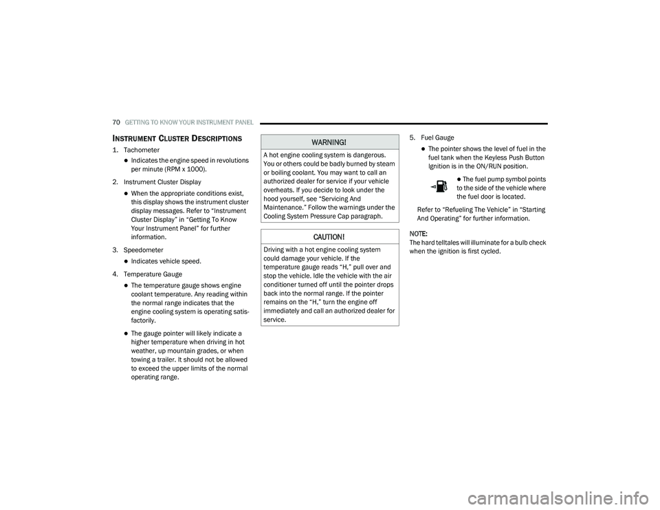
1. Tachometer
Indicates the engine speed in revolutions
per minute (RPM x 1000).
2. Instrument Cluster Display
When the appropriate conditions exist,
this display shows the instrument cluster
display messages. Refer to “Instrument
Cluster Display” in “Getting To Know
Your Instrument Panel” for further
information.
3. Speedometer
Indicates vehicle speed.
4. Temperature Gauge
The temperature gauge shows engine
coolant temperature. Any reading within
the normal range indicates that the
engine cooling system is operating satis -
factorily.
The gauge pointer will likely indicate a
higher temperature when driving in hot
weather, up mountain grades, or when
towing a trailer. It should not be allowed
to exceed the upper limits of the normal
operating range. 5. Fuel Gauge
The pointer shows the level of fuel in the
fuel tank when the Keyless Push Button
Ignition is in the ON/RUN position.
The fuel pump symbol points
to the side of the vehicle where
the fuel door is located.
Refer to “Refueling The Vehicle” in “Starting
And Operating” for further information.
NOTE:
The hard telltales will illuminate for a bulb check
when the ignition is first cycled.
WARNING!
A hot engine cooling system is dangerous.
You or others could be badly burned by steam
or boiling coolant. You may want to call an
authorized dealer for service if your vehicle
overheats. If you decide to look under the
hood yourself, see “Servicing And
Maintenance.” Follow the warnings under the
Cooling System Pressure Cap paragraph.
CAUTION!
Driving with a hot engine cooling system
could damage your vehicle. If the
temperature gauge reads “H,” pull over and
stop the vehicle. Idle the vehicle with the air
conditioner turned off until the pointer drops
back into the normal range. If the pointer
remains on the “H,” turn the engine off
immediately and call an authorized dealer for
service.
20_LA_OM_EN_USC_t.book Page 70
Page 75 of 396
GETTING TO KNOW YOUR INSTRUMENT PANEL73
SRT INSTRUMENT CLUSTER
D
ESCRIPTIONS
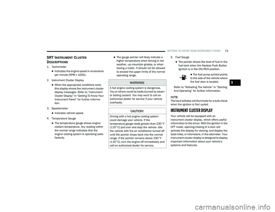
1. Tachometer
Indicates the engine speed in revolutions
per minute (RPM x 1000).
2. Instrument Cluster Display
When the appropriate conditions exist,
this display shows the instrument cluster
display messages. Refer to “Instrument
Cluster Display” in “Getting To Know Your
Instrument Panel” for further informa -
tion.
3. Speedometer
Indicates vehicle speed.
4. Temperature Gauge
The temperature gauge shows engine
coolant temperature. Any reading within
the normal range indicates that the
engine cooling system is operating satis -
factorily.
The gauge pointer will likely indicate a
higher temperature when driving in hot
weather, up mountain grades, or when
towing a trailer. It should not be allowed
to exceed the upper limits of the normal
operating range. 5. Fuel Gauge
The pointer shows the level of fuel in the
fuel tank when the Keyless Push Button
Ignition is in the ON/RUN position.
The fuel pump symbol points
to the side of the vehicle where
the fuel door is located.
Refer to “Refueling The Vehicle” in “Starting
And Operating” for further information.
NOTE:
The hard telltales will illuminate for a bulb check
when the ignition is first cycled.
INSTRUMENT CLUSTER DISPLAY
Your vehicle will be equipped with an
instrument cluster display, which offers useful
information to the driver. With the ignition in the
OFF mode, opening/closing of a door will
activate the display for viewing, and display the
total miles, or kilometers, in the odometer. Your
instrument cluster display is designed to display
important information about your vehicle’s
systems and features.
WARNING!
A hot engine cooling system is dangerous.
You or others could be badly burned by steam
or boiling coolant. You may want to call an
authorized dealer for service if your vehicle
overheats.
CAUTION!
Driving with a hot engine cooling system
could damage your vehicle. If the
temperature gauge reads greater than 230°F
(110°C) pull over and stop the vehicle. Idle
the vehicle with the air conditioner turned off
until the pointer drops back into the normal
range. If the pointer remains above 230°F
(110°C), turn the engine off immediately and
call an authorized dealer for service.
3
20_LA_OM_EN_USC_t.book Page 73
Page 77 of 396
GETTING TO KNOW YOUR INSTRUMENT PANEL75
NOTE:
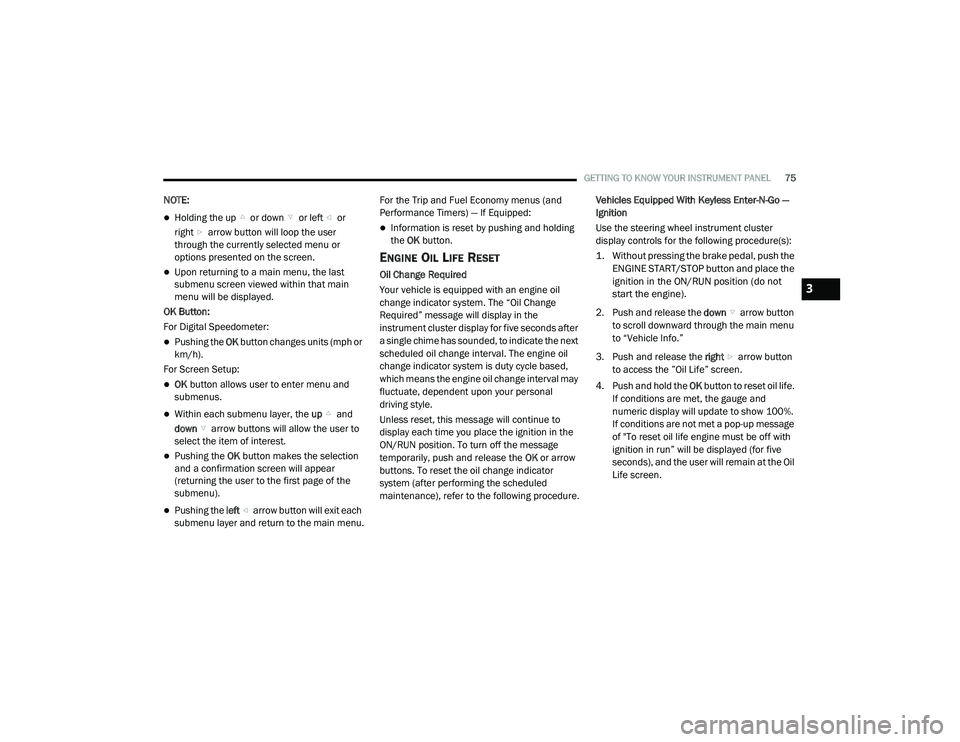
Holding the up or down or left or
right arrow button will loop the user
through the currently selected menu or
options presented on the screen.
Upon returning to a main menu, the last
submenu screen viewed within that main
menu will be displayed.
OK Button:
For Digital Speedometer:
Pushing the OK button changes units (mph or
km/h).
For Screen Setup:
OK button allows user to enter menu and
submenus.
Within each submenu layer, the up and
down arrow buttons will allow the user to
select the item of interest.
Pushing the OK button makes the selection
and a confirmation screen will appear
(returning the user to the first page of the
submenu).
Pushing the left arrow button will exit each
submenu layer and return to the main menu. For the Trip and Fuel Economy menus (and
Performance Timers) — If Equipped:
Information is reset by pushing and holding
the
OK button.
ENGINE OIL LIFE RESET
Oil Change Required
Your vehicle is equipped with an engine oil
change indicator system. The “Oil Change
Required” message will display in the
instrument cluster display for five seconds after
a single chime has sounded, to indicate the next
scheduled oil change interval. The engine oil
change indicator system is duty cycle based,
which means the engine oil change interval may
fluctuate, dependent upon your personal
driving style.
Unless reset, this message will continue to
display each time you place the ignition in the
ON/RUN position. To turn off the message
temporarily, push and release the OK or arrow
buttons. To reset the oil change indicator
system (after performing the scheduled
maintenance), refer to the following procedure. Vehicles Equipped With Keyless Enter-N-Go —
Ignition
Use the steering wheel instrument cluster
display controls for the following procedure(s):
1. Without pressing the brake pedal, push the
ENGINE START/STOP button and place the
ignition in the ON/RUN position (do not
start the engine).
2. Push and release the down arrow button
to scroll downward through the main menu
to “Vehicle Info.”
3. Push and release the right arrow button
to access the ”Oil Life” screen.
4. Push and hold the OK button to reset oil life.
If conditions are met, the gauge and
numeric display will update to show 100%.
If conditions are not met a pop-up message
of "To reset oil life engine must be off with
ignition in run” will be displayed (for five
seconds), and the user will remain at the Oil
Life screen.
3
20_LA_OM_EN_USC_t.book Page 75
Page 78 of 396
76GETTING TO KNOW YOUR INSTRUMENT PANEL
5. Push and release the up or down
arrow button to return to previous main
menu.
NOTE:
If the indicator message illuminates when you
start the vehicle, the oil change indicator
system did not reset. If necessary, repeat this
procedure.
Secondary Method Of Resetting Engine Oil Life
1. Without pressing the brake pedal, push the ENGINE START/STOP button and place the
ignition to the ON/RUN position (do not
start the engine).
2. Fully press the accelerator pedal, slowly, three times within ten seconds.
3. Without pushing the brake pedal, push the ENGINE START/STOP button once to return
the ignition to the OFF/LOCK position.
NOTE:
If the indicator message illuminates when you
start the vehicle, the oil change indicator
system did not reset. If necessary, repeat this
procedure.PERFORMANCE SHIFT INDICATOR (PSI)
— I
F EQUIPPED
The Performance Shift Indicator (PSI) is enabled
on vehicles with manual transmission, or when
a vehicle with automatic transmission is in
manual shift mode. The PSI provides the driver
with a visual indication within the instrument
cluster display when the driver configured gear
shift point has been reached and the driver is
still accelerating. This indication notifies the
driver to change gear corresponding to the
configured RPMs in the head unit.
INSTRUMENT CLUSTER DISPLAY
S
ELECTABLE MENU ITEMS
Push and release the up or down arrow
button until the desired Selectable Menu item is
displayed in the instrument cluster display.
Follow the Menu or submenu prompts as
desired.
Speedometer
Push and release the up or down arrow
button until the speedometer menu is displayed
in the instrument cluster display. Push and
release the OK button to toggle units (km/h or
mph) of the speedometer.
Vehicle Info
Push and release the up or down arrow
button until the “Vehicle Info” menu is displayed
in the instrument cluster display. Push and
release the right or left arrow button to
scroll through the submenus items of “Vehicle
Info.” Follow the directional prompts to access
or reset any of the following “Vehicle Info”
submenu items:
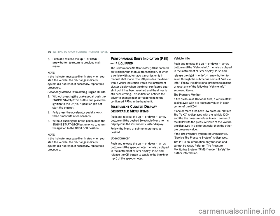
Tire Pressure Monitor
If tire pressure is OK for all tires, a vehicle ICON
is displayed with tire pressure values in each
corner of the ICON.
If one or more tires have low pressure, “Inflate
Tire To XX” is displayed with the vehicle ICON
and the tire pressure values in each corner of
the ICON with the pressure value of the low tire
are displayed in a different color than the other
tire pressure value.
If the Tire Pressure system requires service,
“Service Tire Pressure System” is displayed.
Tire PSI is an information only function and
cannot be reset. Refer to “Tire Pressure
Monitoring System (TPMS)” under “Safety” for
further information.
20_LA_OM_EN_USC_t.book Page 76
Page 79 of 396
GETTING TO KNOW YOUR INSTRUMENT PANEL77
Coolant Temp
Displays the actual coolant temperature.
Trans Temp — If Equipped
Displays the actual transmission tempera -
ture.
Oil Temp
Displays the actual oil temperature.
Oil Pressure
Displays the actual oil pressure.
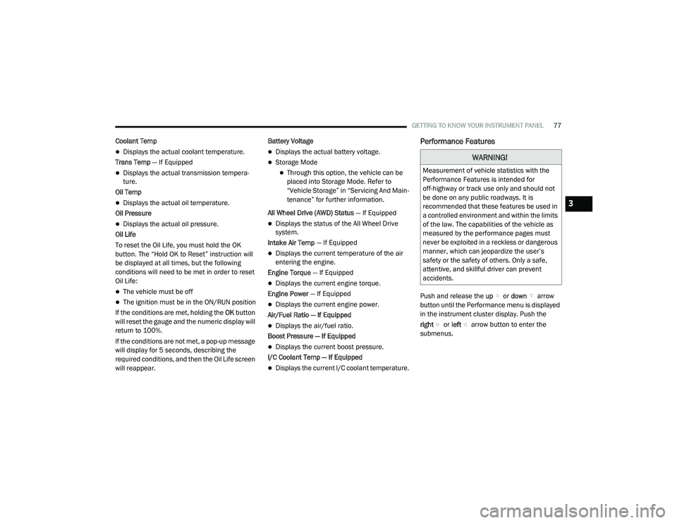
Oil Life
To reset the Oil Life, you must hold the OK
button. The “Hold OK to Reset” instruction will
be displayed at all times, but the following
conditions will need to be met in order to reset
Oil Life:
The vehicle must be off
The ignition must be in the ON/RUN position
If the conditions are met, holding the OK button
will reset the gauge and the numeric display will
return to 100%.
If the conditions are not met, a pop-up message
will display for 5 seconds, describing the
required conditions, and then the Oil Life screen
will reappear. Battery Voltage
Displays the actual battery voltage.
Storage Mode
Through this option, the vehicle can be
placed into Storage Mode. Refer to
“Vehicle Storage” in “Servicing And Main
-
tenance” for further information.
All Wheel Drive (AWD) Status — If Equipped
Displays the status of the All Wheel Drive
system.
Intake Air Temp — If Equipped
Displays the current temperature of the air
entering the engine.
Engine Torque — If Equipped
Displays the current engine torque.
Engine Power — If Equipped
Displays the current engine power.
Air/Fuel Ratio — If Equipped
Displays the air/fuel ratio.
Boost Pressure — If Equipped
Displays the current boost pressure.
I/C Coolant Temp — If Equipped
Displays the current I/C coolant temperature.
Performance Features
Push and release the up or down arrow
button until the Performance menu is displayed
in the instrument cluster display. Push the
right or left arrow button to enter the
submenus.
WARNING!
Measurement of vehicle statistics with the
Performance Features is intended for
off-highway or track use only and should not
be done on any public roadways. It is
recommended that these features be used in
a controlled environment and within the limits
of the law. The capabilities of the vehicle as
measured by the performance pages must
never be exploited in a reckless or dangerous
manner, which can jeopardize the user’s
safety or the safety of others. Only a safe,
attentive, and skillful driver can prevent
accidents.
3
20_LA_OM_EN_USC_t.book Page 77
Page 86 of 396
84GETTING TO KNOW YOUR INSTRUMENT PANEL
Vehicles equipped with the Anti-Lock Brake
System (ABS) are also equipped with Electronic
Brake Force Distribution (EBD). In the event of
an EBD failure, the Brake Warning Light will turn
on along with the ABS Light. Immediate repair to
the ABS system is required.
Operation of the Brake Warning Light can be
checked by turning the ignition switch from the
OFF position to the ON/RUN position. The light
should illuminate for approximately two
seconds. The light should then turn off unless
the parking brake is applied or a brake fault is
detected. If the light does not illuminate, have
the light inspected by an authorized dealer.
The light also will turn on when the parking
brake is applied with the ignition switch in the
ON/RUN position.
NOTE:
This light shows only that the parking brake is
applied. It does not show the degree of brake
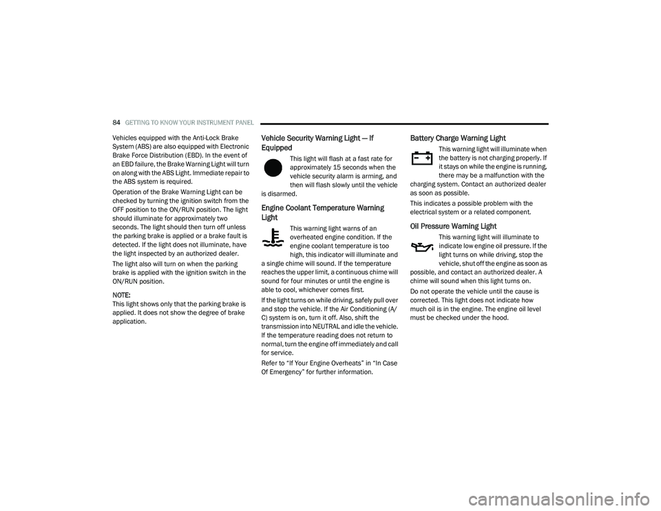
application.Vehicle Security Warning Light — If
Equipped
This light will flash at a fast rate for
approximately 15 seconds when the
vehicle security alarm is arming, and
then will flash slowly until the vehicle
is disarmed.
Engine Coolant Temperature Warning
Light
This warning light warns of an
overheated engine condition. If the
engine coolant temperature is too
high, this indicator will illuminate and
a single chime will sound. If the temperature
reaches the upper limit, a continuous chime will
sound for four minutes or until the engine is
able to cool, whichever comes first.
If the light turns on while driving, safely pull over
and stop the vehicle. If the Air Conditioning (A/
C) system is on, turn it off. Also, shift the
transmission into NEUTRAL and idle the vehicle.
If the temperature reading does not return to
normal, turn the engine off immediately and call
for service.
Refer to “If Your Engine Overheats” in “In Case
Of Emergency” for further information.
Battery Charge Warning Light
This warning light will illuminate when
the battery is not charging properly. If
it stays on while the engine is running,
there may be a malfunction with the
charging system. Contact an authorized dealer
as soon as possible.
This indicates a possible problem with the
electrical system or a related component.
Oil Pressure Warning Light
This warning light will illuminate to
indicate low engine oil pressure. If the
light turns on while driving, stop the
vehicle, shut off the engine as soon as
possible, and contact an authorized dealer. A
chime will sound when this light turns on.
Do not operate the vehicle until the cause is
corrected. This light does not indicate how
much oil is in the engine. The engine oil level
must be checked under the hood.
20_LA_OM_EN_USC_t.book Page 84
Page 87 of 396
GETTING TO KNOW YOUR INSTRUMENT PANEL85
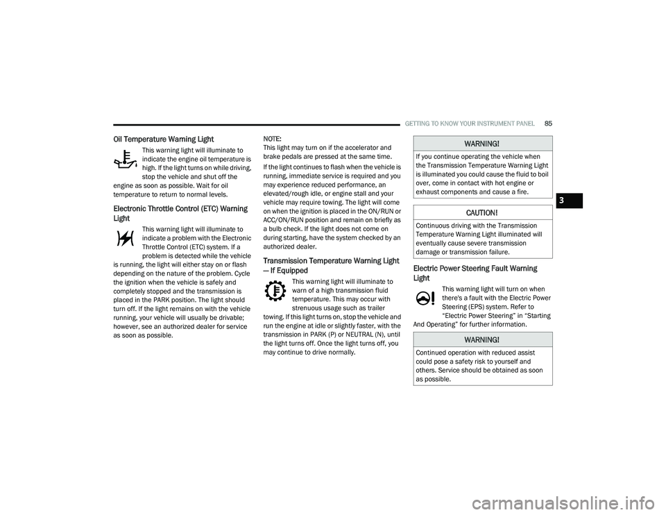
Oil Temperature Warning Light
This warning light will illuminate to
indicate the engine oil temperature is
high. If the light turns on while driving,
stop the vehicle and shut off the
engine as soon as possible. Wait for oil
temperature to return to normal levels.
Electronic Throttle Control (ETC) Warning
Light
This warning light will illuminate to
indicate a problem with the Electronic
Throttle Control (ETC) system. If a
problem is detected while the vehicle
is running, the light will either stay on or flash
depending on the nature of the problem. Cycle
the ignition when the vehicle is safely and
completely stopped and the transmission is
placed in the PARK position. The light should
turn off. If the light remains on with the vehicle
running, your vehicle will usually be drivable;
however, see an authorized dealer for service
as soon as possible. NOTE:
This light may turn on if the accelerator and
brake pedals are pressed at the same time.
If the light continues to flash when the vehicle is
running, immediate service is required and you
may experience reduced performance, an
elevated/rough idle, or engine stall and your
vehicle may require towing. The light will come
on when the ignition is placed in the ON/RUN or
ACC/ON/RUN position and remain on briefly as
a bulb check. If the light does not come on
during starting, have the system checked by an
authorized dealer.
Transmission Temperature Warning Light
— If Equipped
This warning light will illuminate to
warn of a high transmission fluid
temperature. This may occur with
strenuous usage such as trailer
towing. If this light turns on, stop the vehicle and
run the engine at idle or slightly faster, with the
transmission in PARK (P) or NEUTRAL (N), until
the light turns off. Once the light turns off, you
may continue to drive normally.
Electric Power Steering Fault Warning
Light
This warning light will turn on when
there's a fault with the Electric Power
Steering (EPS) system. Refer to
“Electric Power Steering” in “Starting
And Operating” for further information.
WARNING!
If you continue operating the vehicle when
the Transmission Temperature Warning Light
is illuminated you could cause the fluid to boil
over, come in contact with hot engine or
exhaust components and cause a fire.
CAUTION!
Continuous driving with the Transmission
Temperature Warning Light illuminated will
eventually cause severe transmission
damage or transmission failure.
WARNING!
Continued operation with reduced assist
could pose a safety risk to yourself and
others. Service should be obtained as soon
as possible.
3
20_LA_OM_EN_USC_t.book Page 85