low oil pressure DODGE CHALLENGER 2020 Owners Manual
[x] Cancel search | Manufacturer: DODGE, Model Year: 2020, Model line: CHALLENGER, Model: DODGE CHALLENGER 2020Pages: 396, PDF Size: 16.64 MB
Page 5 of 396
3
INTERIOR LIGHTS .................................................43 Map/Reading Lights ................................... 43
Ambient Light — If Equipped ....................... 44
Dimmer Controls ........................................ 44
WINDSHIELD WIPERS AND WASHERS .............45
Wiper Operation ........................................... 45
Rain Sensing Wipers — If Equipped ............ 46
CLIMATE CONTROLS ...........................................47
Automatic Climate Control Overview ......... 47
Climate Control Functions ........................... 52
Automatic Temperature Control (ATC) ....... 52
Operating Tips ............................................. 53
WINDOWS ............................................................54
Power Window Controls............................... 54
Wind Buffeting ............................................ 55
POWER SUNROOF — IF EQUIPPED.....................55
Opening Sunroof .......................................... 56
Closing Sunroof ............................................ 56
Wind Buffeting ............................................ 56
Sunshade Operation.................................... 56
Pinch Protect Feature .................................. 56
Sunroof Maintenance .................................. 57
Ignition Off Operation .................................. 57
HOOD ..................................................................57
To Open The Hood .................................... 57
To Close The Hood ....................................... 57
TRUNK ................................................................58
Opening ........................................................ 58
Closing .......................................................... 58
Trunk Safety ................................................. 59 GARAGE DOOR OPENER — IF EQUIPPED ......... 59
Before You Begin Programming
HomeLink® .................................................. 59 Canadian/Gate Operator Programming ..... 61
Using HomeLink®........................................ 62
Security......................................................... 62
Troubleshooting Tips ................................... 63
General Information .................................... 63
INTERNAL EQUIPMENT ........................................ 64
Storage ......................................................... 64
Cupholders ................................................... 65
Illuminated Cupholders — If Equipped ....... 65
Electrical Power Outlets ............................ 65
GETTING TO KNOW YOUR
INSTRUMENT PANEL
INSTRUMENT CLUSTER ....................................... 68
Instrument Cluster Descriptions ................. 70
SRT INSTRUMENT CLUSTER .............................. 71
SRT Instrument Cluster Descriptions ......... 73
INSTRUMENT CLUSTER DISPLAY....................... 73
Location And Controls ................................. 74
Engine Oil Life Reset ................................. 75
Performance Shift Indicator (PSI) —
If Equipped ................................................... 76 Instrument Cluster Display Selectable
Menu Items .................................................. 76 Battery Saver On/Battery Saver Mode
Message — Electrical Load Reduction
Actions — If Equipped ............................... 81 WARNING LIGHTS AND MESSAGES ..................82
Red Warning Lights ..................................... 83
Yellow Warning Lights ................................. 86
Yellow Indicator Lights ................................ 89
Green Indicator Lights ................................. 89
White Indicator Lights ................................. 90
Blue Indicator Lights ................................... 91
ONBOARD DIAGNOSTIC SYSTEM —
OBD II ..................................................................91
Onboard Diagnostic System
(OBD II) Cybersecurity ................................. 91
EMISSIONS INSPECTION AND
MAINTENANCE PROGRAMS ...............................92
SAFETY
SAFETY FEATURES ...............................................93
Anti-Lock Brake System (ABS) ................... 93
Electronic Brake Control (EBC) System ..... 94
AUXILIARY DRIVING SYSTEMS ........................ 100
Blind Spot Monitoring (BSM) —
If Equipped ................................................. 100 Forward Collision Warning (FCW)
Operation - If Equipped ............................. 105 Tire Pressure Monitoring System
(TPMS) ........................................................ 107
20_LA_OM_EN_USC_t.book Page 3
Page 72 of 396
70GETTING TO KNOW YOUR INSTRUMENT PANEL
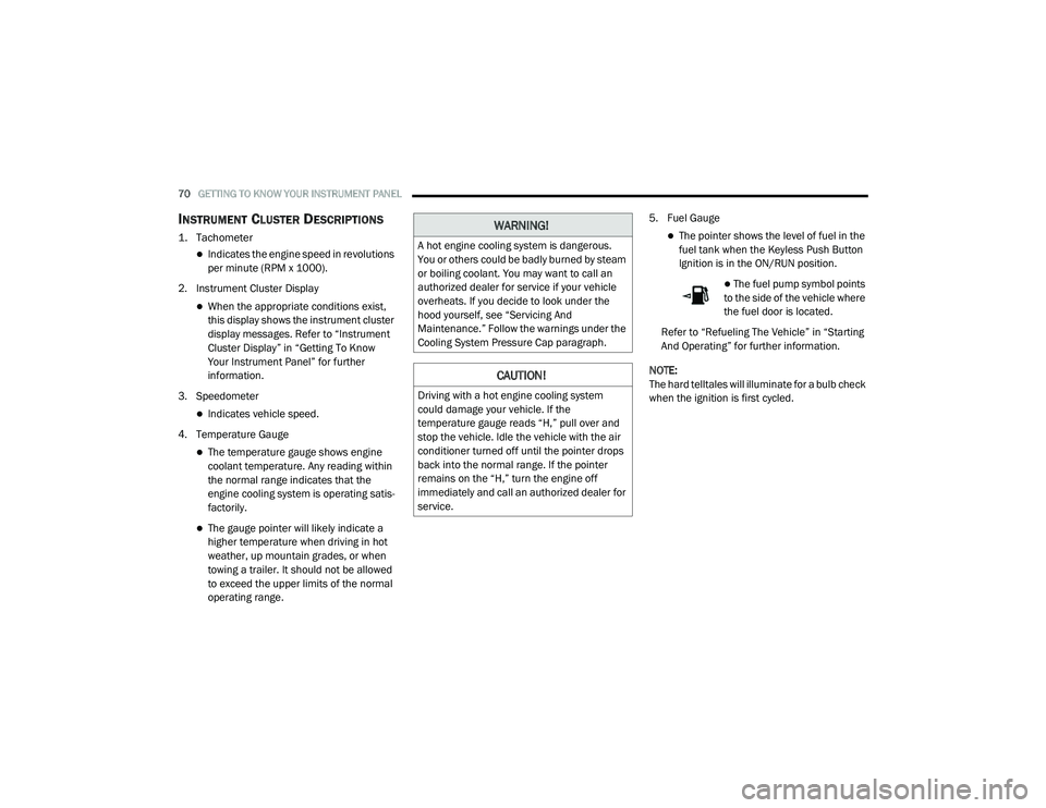
INSTRUMENT CLUSTER DESCRIPTIONS
1. Tachometer
Indicates the engine speed in revolutions
per minute (RPM x 1000).
2. Instrument Cluster Display
When the appropriate conditions exist,
this display shows the instrument cluster
display messages. Refer to “Instrument
Cluster Display” in “Getting To Know
Your Instrument Panel” for further
information.
3. Speedometer
Indicates vehicle speed.
4. Temperature Gauge
The temperature gauge shows engine
coolant temperature. Any reading within
the normal range indicates that the
engine cooling system is operating satis -
factorily.
The gauge pointer will likely indicate a
higher temperature when driving in hot
weather, up mountain grades, or when
towing a trailer. It should not be allowed
to exceed the upper limits of the normal
operating range. 5. Fuel Gauge
The pointer shows the level of fuel in the
fuel tank when the Keyless Push Button
Ignition is in the ON/RUN position.
The fuel pump symbol points
to the side of the vehicle where
the fuel door is located.
Refer to “Refueling The Vehicle” in “Starting
And Operating” for further information.
NOTE:
The hard telltales will illuminate for a bulb check
when the ignition is first cycled.
WARNING!
A hot engine cooling system is dangerous.
You or others could be badly burned by steam
or boiling coolant. You may want to call an
authorized dealer for service if your vehicle
overheats. If you decide to look under the
hood yourself, see “Servicing And
Maintenance.” Follow the warnings under the
Cooling System Pressure Cap paragraph.
CAUTION!
Driving with a hot engine cooling system
could damage your vehicle. If the
temperature gauge reads “H,” pull over and
stop the vehicle. Idle the vehicle with the air
conditioner turned off until the pointer drops
back into the normal range. If the pointer
remains on the “H,” turn the engine off
immediately and call an authorized dealer for
service.
20_LA_OM_EN_USC_t.book Page 70
Page 78 of 396
76GETTING TO KNOW YOUR INSTRUMENT PANEL
5. Push and release the up or down
arrow button to return to previous main
menu.
NOTE:
If the indicator message illuminates when you
start the vehicle, the oil change indicator
system did not reset. If necessary, repeat this
procedure.
Secondary Method Of Resetting Engine Oil Life
1. Without pressing the brake pedal, push the ENGINE START/STOP button and place the
ignition to the ON/RUN position (do not
start the engine).
2. Fully press the accelerator pedal, slowly, three times within ten seconds.
3. Without pushing the brake pedal, push the ENGINE START/STOP button once to return
the ignition to the OFF/LOCK position.
NOTE:
If the indicator message illuminates when you
start the vehicle, the oil change indicator
system did not reset. If necessary, repeat this
procedure.PERFORMANCE SHIFT INDICATOR (PSI)
— I
F EQUIPPED
The Performance Shift Indicator (PSI) is enabled
on vehicles with manual transmission, or when
a vehicle with automatic transmission is in
manual shift mode. The PSI provides the driver
with a visual indication within the instrument
cluster display when the driver configured gear
shift point has been reached and the driver is
still accelerating. This indication notifies the
driver to change gear corresponding to the
configured RPMs in the head unit.
INSTRUMENT CLUSTER DISPLAY
S
ELECTABLE MENU ITEMS
Push and release the up or down arrow
button until the desired Selectable Menu item is
displayed in the instrument cluster display.
Follow the Menu or submenu prompts as
desired.
Speedometer
Push and release the up or down arrow
button until the speedometer menu is displayed
in the instrument cluster display. Push and
release the OK button to toggle units (km/h or
mph) of the speedometer.
Vehicle Info
Push and release the up or down arrow
button until the “Vehicle Info” menu is displayed
in the instrument cluster display. Push and
release the right or left arrow button to
scroll through the submenus items of “Vehicle
Info.” Follow the directional prompts to access
or reset any of the following “Vehicle Info”
submenu items:
Tire Pressure Monitor
If tire pressure is OK for all tires, a vehicle ICON
is displayed with tire pressure values in each
corner of the ICON.
If one or more tires have low pressure, “Inflate
Tire To XX” is displayed with the vehicle ICON
and the tire pressure values in each corner of
the ICON with the pressure value of the low tire
are displayed in a different color than the other
tire pressure value.
If the Tire Pressure system requires service,
“Service Tire Pressure System” is displayed.
Tire PSI is an information only function and
cannot be reset. Refer to “Tire Pressure
Monitoring System (TPMS)” under “Safety” for
further information.
20_LA_OM_EN_USC_t.book Page 76
Page 79 of 396
GETTING TO KNOW YOUR INSTRUMENT PANEL77
Coolant Temp
Displays the actual coolant temperature.
Trans Temp — If Equipped
Displays the actual transmission tempera -
ture.
Oil Temp
Displays the actual oil temperature.
Oil Pressure
Displays the actual oil pressure.
Oil Life
To reset the Oil Life, you must hold the OK
button. The “Hold OK to Reset” instruction will
be displayed at all times, but the following
conditions will need to be met in order to reset
Oil Life:
The vehicle must be off
The ignition must be in the ON/RUN position
If the conditions are met, holding the OK button
will reset the gauge and the numeric display will
return to 100%.
If the conditions are not met, a pop-up message
will display for 5 seconds, describing the
required conditions, and then the Oil Life screen
will reappear. Battery Voltage
Displays the actual battery voltage.
Storage Mode
Through this option, the vehicle can be
placed into Storage Mode. Refer to
“Vehicle Storage” in “Servicing And Main
-
tenance” for further information.
All Wheel Drive (AWD) Status — If Equipped
Displays the status of the All Wheel Drive
system.
Intake Air Temp — If Equipped
Displays the current temperature of the air
entering the engine.
Engine Torque — If Equipped
Displays the current engine torque.
Engine Power — If Equipped
Displays the current engine power.
Air/Fuel Ratio — If Equipped
Displays the air/fuel ratio.
Boost Pressure — If Equipped
Displays the current boost pressure.
I/C Coolant Temp — If Equipped
Displays the current I/C coolant temperature.
Performance Features
Push and release the up or down arrow
button until the Performance menu is displayed
in the instrument cluster display. Push the
right or left arrow button to enter the
submenus.
WARNING!
Measurement of vehicle statistics with the
Performance Features is intended for
off-highway or track use only and should not
be done on any public roadways. It is
recommended that these features be used in
a controlled environment and within the limits
of the law. The capabilities of the vehicle as
measured by the performance pages must
never be exploited in a reckless or dangerous
manner, which can jeopardize the user’s
safety or the safety of others. Only a safe,
attentive, and skillful driver can prevent
accidents.
3
20_LA_OM_EN_USC_t.book Page 77
Page 86 of 396
84GETTING TO KNOW YOUR INSTRUMENT PANEL
Vehicles equipped with the Anti-Lock Brake
System (ABS) are also equipped with Electronic
Brake Force Distribution (EBD). In the event of
an EBD failure, the Brake Warning Light will turn
on along with the ABS Light. Immediate repair to
the ABS system is required.
Operation of the Brake Warning Light can be
checked by turning the ignition switch from the
OFF position to the ON/RUN position. The light
should illuminate for approximately two
seconds. The light should then turn off unless
the parking brake is applied or a brake fault is
detected. If the light does not illuminate, have
the light inspected by an authorized dealer.
The light also will turn on when the parking
brake is applied with the ignition switch in the
ON/RUN position.
NOTE:
This light shows only that the parking brake is
applied. It does not show the degree of brake
application.Vehicle Security Warning Light — If
Equipped
This light will flash at a fast rate for
approximately 15 seconds when the
vehicle security alarm is arming, and
then will flash slowly until the vehicle
is disarmed.
Engine Coolant Temperature Warning
Light
This warning light warns of an
overheated engine condition. If the
engine coolant temperature is too
high, this indicator will illuminate and
a single chime will sound. If the temperature
reaches the upper limit, a continuous chime will
sound for four minutes or until the engine is
able to cool, whichever comes first.
If the light turns on while driving, safely pull over
and stop the vehicle. If the Air Conditioning (A/
C) system is on, turn it off. Also, shift the
transmission into NEUTRAL and idle the vehicle.
If the temperature reading does not return to
normal, turn the engine off immediately and call
for service.
Refer to “If Your Engine Overheats” in “In Case
Of Emergency” for further information.
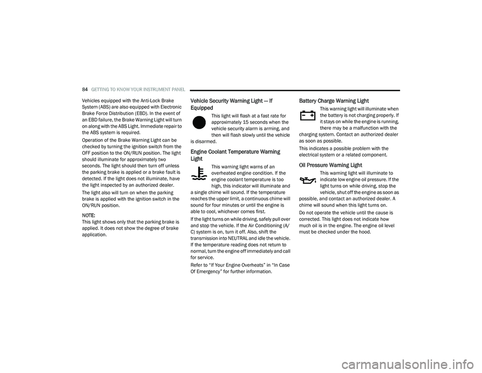
Battery Charge Warning Light
This warning light will illuminate when
the battery is not charging properly. If
it stays on while the engine is running,
there may be a malfunction with the
charging system. Contact an authorized dealer
as soon as possible.
This indicates a possible problem with the
electrical system or a related component.
Oil Pressure Warning Light
This warning light will illuminate to
indicate low engine oil pressure. If the
light turns on while driving, stop the
vehicle, shut off the engine as soon as
possible, and contact an authorized dealer. A
chime will sound when this light turns on.
Do not operate the vehicle until the cause is
corrected. This light does not indicate how
much oil is in the engine. The engine oil level
must be checked under the hood.
20_LA_OM_EN_USC_t.book Page 84
Page 227 of 396
IN CASE OF EMERGENCY225
(D) Drive Vehicle:
Immediately after injecting sealant and inflating
the tire, drive the vehicle 5 miles (8 km) or ten
minutes to ensure distribution of the Tire
Service Kit Sealant within the tire. Do not
exceed 50 mph (80 km/h).
(E) After Driving:
Pull over to a safe location. Refer to “(A)
Whenever You Stop To Use Tire Service Kit”
before continuing.
1. Push in the Mode Select Knob (2) and turn to the Air Mode position.
2. Uncoil the power plug and insert the plug into the vehicle's 12 Volt power outlet.
3. Uncoil the Air Pump Hose (5) (black in color) and screw the fitting at the end of hose onto
the valve stem.
4. Check the pressure in the tire by reading the Pressure Gauge (8). If tire pressure is less than 19 psi (1.3 Bar):
The tire is too badly damaged. Do not attempt to
drive the vehicle further. Call for assistance.
If the tire pressure is 19 psi (1.3 Bar) or higher:
1. Push the Power Button (1) to turn on Tire
Service Kit and inflate the tire to the
pressure indicated on the tire and loading
information label on the driver-side door
opening.
NOTE:
If the tire becomes over-inflated, push the
Deflation Button to reduce the tire pressure to
the recommended inflation pressure before
continuing.
2. Disconnect the Tire Service Kit from the valve stem, reinstall the cap on the valve
stem and unplug from 12 Volt outlet.
3. Place the Tire Service Kit in its proper storage area in the vehicle.
4. Have the tire inspected and repaired or replaced at the earliest opportunity at an
authorized dealer or tire service center.
CAUTION!
The metal end fitting from Power Plug (8)
may get hot after use, so it should be
handled carefully.
Failure to reinstall the cap on the fitting at
the end of the Sealant Hose (6) can result
in sealant contacting your skin, clothing,
and the vehicle’s interior. It can also result
in sealant contacting internal Tire Service
Kit components which may cause perma -
nent damage to the kit.
WARNING!
Tire Service Kit is not a permanent flat tire
repair. Have the tire inspected and repaired
or replaced after using Tire Service Kit. Do
not exceed 50 mph (80 km/h) until the tire is
repaired or replaced. Failure to follow this
warning can result in injuries that are serious
or fatal to you, your passengers, and others
around you.
6
20_LA_OM_EN_USC_t.book Page 225
Page 236 of 396
234
SERVICING AND MAINTENANCE
SCHEDULED SERVICING
3.6L AND 5.7L ENGINES
These engines are equipped with an automatic
oil change indicator system. The oil change
indicator system will remind you that it is time to
take your vehicle in for scheduled maintenance.
Based on engine operation conditions, the oil
change indicator message will illuminate. This
means that service is required for the vehicle.
Operating conditions such as frequent
short-trips, trailer tow, and extremely hot or cold
ambient temperatures will influence when the
“Change Oil” or “Oil Change Required” message
is displayed. Severe Operating Conditions can
cause the change oil message to illuminate as
early as 3,500 miles (5,600 km) since last
reset. Have your vehicle serviced as soon as
possible, within the next 500 miles (805 km).
The “Oil Change Required” message will be
displayed in the instrument cluster and a single
chime will sound, indicating that an oil change
is necessary.An authorized dealer will reset the oil change
indicator message after completing the
scheduled oil change. If a scheduled oil change
is performed by someone other than an
authorized dealer, the message can be reset by
referring to “Instrument Cluster Display” in
“Getting To Know Your Instrument Panel” for
further information.
NOTE:
Under no circumstances should oil change
intervals exceed 10,000 miles (16,000 km),
12 months or 350 hours of engine run time,
whichever comes first. The 350 hours of engine
run or idle time is generally only a concern for
fleet customers.
Severe Duty All Models
Change Engine Oil at 4,000 miles (6,500 km) or
350 hours of engine run time if the vehicle is
operated in a dusty and off-road environment,
or is operated predominantly at idle or only very
low engine RPM. This type of vehicle use is
considered Severe Duty.
Once A Month Or Before A Long Trip:
Check engine oil level.
Check windshield washer fluid level.
Check tire pressure and look for unusual
wear or damage. Rotate tires at the first sign
of irregular wear, even if it occurs before your
next scheduled service.
Check the fluid levels of the coolant reservoir,
brake master cylinder and fill as needed.
Check function of all interior and exterior
lights.
Maintenance Plan — 3.6L And 5.7L
Required Maintenance Intervals
Refer to the maintenance chart for the required
maintenance intervals.
20_LA_OM_EN_USC_t.book Page 234
Page 241 of 396
SERVICING AND MAINTENANCE239
Heavy Duty Use Of The Vehicle
Change engine oil at 4,000 miles (6,500 km) or
350 hours of engine run time if the vehicle is
operated in a dusty and off road environment or
is operated predominately at idle or only very
low engine RPM. This type of vehicle use is
considered Severe Duty.
6.2L SUPERCHARGED AND 6.4L
E
NGINES
The scheduled maintenance services listed in
this manual must be done at the times or
mileages specified to protect your vehicle
warranty and ensure the best vehicle
performance and reliability. More frequent
maintenance may be needed for vehicles in
severe operating conditions, such as dusty
areas and very short trip driving. Inspection and
service should also be done anytime a
malfunction is suspected.
The oil change indicator system will remind you
that it is time to take your vehicle in for
scheduled maintenance.
An “Oil Change Required” message will be
displayed in the instrument cluster and a single
chime will sound, indicating that an oil change
is necessary. Based on engine operation conditions, the oil
change indicator message will illuminate. This
means that service is required for your vehicle.
Have your vehicle serviced as soon as possible,
within the next 500 miles (805 km).
NOTE:
The oil change indicator message will not
monitor the time since the last oil change.
Change your vehicle's oil if it has been six
months since your last oil change, even if the
oil change indicator message is NOT illumi-
nated.
Change your engine oil more often if you drive
your vehicle off-road/track usage for an
extended period of time.
Under no circumstances should oil change
intervals exceed 6,000 miles (10,000 km) or
6 months, whichever comes first.
An authorized dealer will reset the oil change
indicator message after completing the
scheduled oil change. If a scheduled oil change
is performed by someone other than an
authorized dealer, the message can be reset by
referring to the steps described under
“Instrument Cluster Display” in “Getting To
Know Your Instrument Panel” for further
information. At Each Stop For Fuel
Check the engine oil level. Refer to “Engine
Compartment” in this chapter for further
information.
Check the windshield washer solvent and
add if required.
Once A Month
Check tire pressure and look for unusual
wear or damage.
Inspect the battery, and clean and tighten the
terminals as required.
Check the fluid levels of the coolant reservoir,
brake master cylinder and add as needed.
Check all lights and other electrical items for
correct operation.
At Each Oil Change
Change the engine oil filter.
Inspect the brake hoses and lines.
Inspect the CV/Universal joints.
CAUTION!
Failure to perform the required maintenance
items may result in damage to the vehicle.
7
20_LA_OM_EN_USC_t.book Page 239
Page 252 of 396
250SERVICING AND MAINTENANCE
CHECKING OIL LEVEL — 3.6L AND 5.7L
E
NGINE
To ensure proper engine lubrication, the engine
oil must be maintained at the correct level.
Check the oil level at regular intervals, such as
every month. The best time to check the engine
oil level is about five minutes after a fully
warmed up engine is shut off.
Checking the oil while the vehicle is on level
ground will improve the accuracy of the oil level
readings.
There are three possible dipstick types:
Crosshatched zone.
Crosshatched zone marked SAFE.
Crosshatched zone marked with MIN at the
low end of the range and MAX at the high end
of the range.
NOTE:
Always maintain the oil level within the cross -
hatch markings on the dipstick.
Adding 1 Quart (1.0 Liter) of oil when the
reading is at the low end of the dipstick range
will raise the oil level to the high end of the
range marking.
CHECKING OIL LEVEL — 6.2L
S
UPERCHARGED ENGINE AND 6.4L
E
NGINE
To ensure proper engine lubrication, the engine
oil must be maintained at the correct level.
Check the oil level at regular intervals, such as
once a month. The best time to check the
engine oil level is about five minutes after a fully
warmed engine is shut off.
Checking the oil while the vehicle is on level
ground will improve the accuracy of the oil level
readings. Maintain the oil level in the “SAFE”
range. Adding 1.0 Quart (1 Liter) of oil when the
reading is at the bottom of the “SAFE” range will
result in an oil level at the top of the “SAFE”
range on these engines.
ADDING WASHER FLUID
The windshield washer fluid reservoir is located
in the front of the engine compartment. Be sure
to check the fluid level at regular intervals. Fill
the reservoir with windshield washer solvent
(not radiator antifreeze) and operate the system
for a few seconds to flush out the residual
water.
When refilling the washer fluid reservoir, apply
some washer fluid to a cloth or towel and wipe
the wiper blades clean. This will help blade
performance.
To prevent freeze-up of your windshield washer
system in cold weather, select a solution or
mixture that meets or exceeds the temperature
range of your climate. This rating information
can be found on most washer fluid containers.
The fluid reservoir will hold nearly 1 Gallon
(4 Liters) of washer fluid when the message
“Low Washer Fluid” appears in the instrument
cluster.CAUTION!
Overfilling or underfilling the crankcase will
cause aeration or loss of oil pressure. This
could damage your engine.
CAUTION!
Overfilling or underfilling the crankcase will
cause aeration or loss of oil pressure. This
could damage your engine.
WARNING!
Commercially available windshield washer
solvents are flammable. They could ignite and
burn you. Care must be exercised when filling
or working around the washer solution.
20_LA_OM_EN_USC_t.book Page 250
Page 258 of 396
256SERVICING AND MAINTENANCE
Engine Air Cleaner Filter Selection
The quality of replacement engine air cleaner
filters varies considerably. Only high quality
filters should be used to ensure most efficient
service. Mopar engine air cleaner filters are a
high quality filter and are recommended.
T/A Air Filter Maintenance — If Equipped
Clean Engine Air Filter
The scheduled air filter cleaning interval is
30,000 miles (48,280 km), or if in a dusty
environment the engine air filter should be
checked periodically to ensure optimal air flow.
Cleaning your engine air filter with the
recommended Mopar Performance Air Filter
Service Kit is not required if you can still see any
part the wire screen on the entire air filter
regardless of how dirty it may appear. When any
part of the wire screen is no longer visible on the
air filter, that is an indication it is time to clean
the air filter.
1. Spray the air filter with the recommended
Mopar air filter cleaner and let sit for at
least 10 minutes to loosen dirt, before
rinsing.
NOTE:
Never use strong detergents, high pressure, or
gasoline on air filter. 2. Rinse the air filter with cool low-pressure
water applied from the inside (clean side)
out in order to flush the dirt out of the filter.
Continue to rinse the filter until all traces of
the cleaner have been removed.
NOTE:
It may be necessary to repeat steps 1 and 2 if
the air filter is not completely clean.
3. After rinsing the air filter, gently shake off the excess water and allow air filter to dry
naturally. Do not apply oil until air filter is
completely dry.
NOTE:
Do not use forced air pressure as it may
damage the filtering capabilities of the filter’s
microfibers and also void its warranty.
4. Using the Mopar Performance Air Filter Service Kit, spray oil evenly along the crown
of each filter pleat holding the nozzle about
3 inches (76 mm) away from the air filter.
One spray per 2 square inches
(1,290 square mm) of air filter. With one
complete coat of oil, let it wick (saturate) for
about 20 minutes, and if required touch up
any light areas on either side of the filter.WARNING!
The air induction system (air cleaner, hoses,
etc.) can provide a measure of protection in
the case of engine backfire. Do not remove
the air induction system (air cleaner, hoses,
etc.) unless such removal is necessary for
repair or maintenance. Make sure that no
one is near the engine compartment before
starting the vehicle with the air induction
system (air cleaner, hoses, etc.) removed.
Failure to do so can result in serious personal
injury.
20_LA_OM_EN_USC_t.book Page 256