audio DODGE CHALLENGER 2021 Owners Manual
[x] Cancel search | Manufacturer: DODGE, Model Year: 2021, Model line: CHALLENGER, Model: DODGE CHALLENGER 2021Pages: 328, PDF Size: 15 MB
Page 7 of 328
5
TRAILER TOWING ............................................... 111 Common Towing Definitions ......................... 111Trailer Hitch Classification ............................ 113
Trailer Towing Weights (Maximum Trailer
Weight Ratings) ............................................. 113
Trailer And Tongue Weight ........................... 114
Towing Requirements ................................... 114Towing Tips ................................................... 116
RECREATIONAL TOWING
(BEHIND MOTORHOME) ..................................... 117
DRIVING TIPS ....................................................... 117
Driving On Slippery Surfaces ........................ 117
Driving Through Water ................................. 118
MULTIMEDIA
UCONNECT SYSTEMS ......................................... 119
CYBERSECURITY ................................................. 119
UCONNECT SETTINGS ........................................ 120Customer Programmable Features .............. 120
UCONNECT INTRODUCTION................................ 135
System Overview .......................................... 135
Drag & Drop Menu Bar ................................. 138Safety And General Information ................... 138
UCONNECT MODES ............................................. 139
Steering Wheel Audio Controls ..................... 139
Radio Mode .................................................. 140
Media Mode .................................................. 148
Phone Mode ................................................. 150 ANDROID AUTO™ & APPLE CARPLAY® —
IF EQUIPPED ........................................................ 161
Android Auto™ .............................................. 161
Apple CarPlay® ............................................. 163Android Auto™ And Apple CarPlay®
Tips And Tricks .............................................. 165
PERFORMANCE PAGES...................................... 165
Home.............................................................. 166
Timers ............................................................ 168
Gauges ........................................................... 170
G-Force........................................................... 171
Engine ............................................................ 172
Dynamometer (Dyno) .................................... 172
DODGE DRIVE MODES — IF EQUIPPED ............ 173
Performance Control — If Equipped ............. 173
RADIO OPERATION AND MOBILE PHONES ..... 177
Regulatory And Safety Information .............. 177
SAFETY
SAFETY FEATURES .............................................. 178 Anti-Lock Brake System (ABS) ..................... 178
Electronic Brake Control (EBC) System ...... 179
AUXILIARY DRIVING SYSTEMS.......................... 184
Blind Spot Monitoring (BSM) —
If Equipped..................................................... 184Forward Collision Warning (FCW) Operation —
If Equipped..................................................... 187Tire Pressure Monitoring System (TPMS) .... 189 OCCUPANT RESTRAINT SYSTEMS ................... 192
Occupant Restraint Systems Features ....... 192
Important Safety Precautions ...................... 192
Seat Belt Systems ........................................ 193
Supplemental Restraint Systems (SRS) ...... 199Child Restraints ............................................ 208
SAFETY TIPS ........................................................ 223
Transporting Passengers.............................. 223
Transporting Pets ......................................... 223
Safety Checks You Should Make Inside
The Vehicle ................................................... 223
Periodic Safety Checks You Should Make
Outside The Vehicle ...................................... 225
Exhaust Gas................................................... 225
Carbon Monoxide Warnings ......................... 225
IN CASE OF EMERGENCY
HAZARD WARNING FLASHERS ......................... 226
ASSIST AND SOS MIRROR — IF EQUIPPED...... 226
JACKING AND TIRE CHANGING ......................... 229 Preparations For Jacking .............................. 230
Jack Location/Spare Tire Stowage ............. 230
Jacking And Changing A Tire ....................... 231
TIRE SERVICE KIT — IF EQUIPPED ..................... 234
Tire Service Kit Storage ................................ 234
Tire Service Kit Components And Operation ...234
Tire Service Kit Usage Precautions .............. 235
Sealing A Tire With Tire Service Kit .............. 236
21_LA_OM_EN_USC_t.book Page 5
Page 56 of 328
54GETTING TO KNOW YOUR VEHICLE
USB/AUX CONTROL
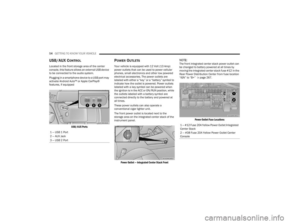
Located in the front storage area of the center
console, this feature allows an external USB device
to be connected to the audio system.
Plugging in a smartphone device to a USB port may
activate Android Auto™ or Apple CarPlay®
features, if equipped
USB/AUX Ports
POWER OUTLETS
Your vehicle is equipped with 12 Volt (13 Amp)
power outlets that can be used to power cellular
phones, small electronics and other low powered
electrical accessories. The power outlets are
labeled with either a “key” or a “battery” symbol to
indicate how the outlet is powered. Power outlets
labeled with a key symbol can be powered when
the ignition is in the ACC or ON/RUN position, while
the outlets labeled with a battery symbol are
connected directly to the battery and powered at
all times.
These power outlets can also operate a
conventional cigar lighter unit.
The front power outlet is located next to the
storage area on the integrated center stack of the
instrument panel.
Power Outlet — Integrated Center Stack Front
NOTE:The front integrated center stack power outlet can
be changed to battery powered at all times by
moving the integrated center stack fuse #12 in the
Rear Power Distribution Center from fuse location
“IGN” to “B+” Ú page 267.
Power Outlet Fuse Locations
1 — USB 1 Port
2 — AUX Jack
3 — USB 2 Port
1 — #12 Fuse 20A Yellow Power Outlet Integrated
Center Stack
2 — #38 Fuse 20A Yellow Power Outlet Center
Console
21_LA_OM_EN_USC_t.book Page 54
Page 65 of 328
GETTING TO KNOW YOUR INSTRUMENT PANEL63
LOCATION AND CONTROLS
The instrument cluster display features an
interactive display which is located in the
instrument cluster.
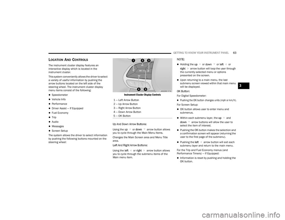
This system conveniently allows the driver to select
a variety of useful information by pushing the
arrow buttons located on the left side of the
steering wheel. The instrument cluster display
menu items consist of the following:
Speedometer
Vehicle Info
Performance
Driver Assist — If Equipped
Fuel Economy
Trip
Audio
Messages
Screen Setup
The system allows the driver to select information
by pushing the following buttons mounted on the
steering wheel:
Instrument Cluster Display Controls
Up And Down Arrow Buttons:
Using the up or down arrow button allows
you to cycle through the Main Menu Items.
Changes the Main Screen area and Menu Title
area.
Left And Right Arrow Buttons:
Using the left or right arrow button allows
you to cycle through the submenu items of the
Main menu item.
NOTE:
Holding the up or down or left or
right arrow button will loop the user through
the currently selected menu or options
presented on the screen.
Upon returning to a main menu, the last
submenu screen viewed within that main menu
will be displayed.
OK Button:
For Digital Speedometer:
Pushing the OK button changes units (mph or km/h).
For Screen Setup:
OK button allows user to enter menu and
submenus.
Within each submenu layer, the up and
down arrow buttons will allow the user to
select the item of interest.
Pushing the OK button makes the selection and
a confirmation screen will appear (returning the
user to the first page of the submenu).
Pushing the left arrow button will exit each
submenu layer and return to the main menu.
For the Trip and Fuel Economy menus (and
Performance Timers) — If Equipped:
Information is reset by pushing and holding the
OK button.
1 — Left Arrow Button
2 — Up Arrow Button
3 — Right Arrow Button
4 — Down Arrow Button
5 — OK Button
3
21_LA_OM_EN_USC_t.book Page 63
Page 69 of 328
GETTING TO KNOW YOUR INSTRUMENT PANEL67
Fuel Economy
Two submenu pages; one with Current Value
(instantaneous calculation of the fuel economy)
displayed and one without the Current Value
displayed (toggle the left or right arrow
button to select one):
Current Fuel Economy (MPG, L/100 km, or
km/L).
Range To Empty (miles or km).
Average Fuel Economy (MPG, L/100 km, or
km/L).
The Max and Min values will correspond to the
particular engine requirements.
Lower end of gauge will be displayed in an
amber color and turn green as Fuel Economy
improves.
Hold the OK button to reset average fuel
economy information.
Trip Info
Push and release the up or down arrow
button until the Trip Menu item is displayed in the
instrument cluster display. Toggle the left or
right arrow button to select Trip A or Trip B. The
Trip information will display the following:
Distance – Shows the total distance (mi or km)
traveled for Trip A or Trip B since the last reset.
Average Fuel Economy – Shows the average
fuel economy (MPG, L/100km or km/L) of Trip A
or Trip B since the last reset.
Elapsed Time – Shows the total elapsed time of
travel since the last reset.
Hold the OK button to reset feature information.
Audio
This menu displays the Audio information of the
currently playing audio source (e.g. FM radio).
Messages
This feature shows the number of stored warning
messages, if any. Pushing the right or left
arrow button will allow you to scroll through the
stored messages.
Screen Setup
Push and release the up or down arrow
button until the Screen Setup Menu displays in the
instrument cluster display. Push and release the
OK button to enter the submenus. The Screen
Setup feature allows you to change what
information is displayed in the instrument cluster
as well as the location that information is
displayed.
1. Upper Left
Compass
Outside Temp
Time
Range to Empty
Average (MPG, L/100 km, or km/L)
Current (MPG, L/100 km, or km/L)
Trip A Distance
Trip B Distance
None
2. Upper Right
Compass
Outside Temp
Time
Range to Empty
Average (MPG, L/100 km, or km/L)
Current (MPG, L/100 km, or km/L)
Trip A Distance
Trip B Distance
None
3
21_LA_OM_EN_USC_t.book Page 67
Page 70 of 328
68GETTING TO KNOW YOUR INSTRUMENT PANEL
3. Center
Menu Title
Compass
Outside Temp
Time
Range to Empty
Average (MPG, L/100 km, or km/L)
Current (MPG, L/100 km, or km/L)
Trip A Distance
Trip B Distance
Audio Information
Digital Speed
None
4. Current Gear
On
Off
5. Odometer
Show
Hide
6. Gear Display
Full
Single 7. Restore Defaults
Ok
Cancel
BATTERY SAVER ON/BATTERY SAVER
M
ODE MESSAGE — ELECTRICAL LOAD
R
EDUCTION ACTIONS — IF EQUIPPED
This vehicle is equipped with an Intelligent Battery
Sensor (IBS) to perform additional monitoring of
the electrical system and status of the vehicle
battery.
In cases when the IBS detects charging system
failure, or the vehicle battery conditions are
deteriorating, electrical load reduction actions will
take place to extend the driving time and distance
of the vehicle. This is done by reducing power to or
turning off non-essential electrical loads.
Load reduction is only active when the engine is
running. It will display a message if there is a risk
of battery depletion to the point where the vehicle
may stall due to lack of electrical supply, or will not
restart after the current drive cycle.
When load reduction is activated, the message
“Battery Saver On” or “Battery Saver Mode” will
appear in the instrument cluster. These messages indicate the vehicle battery has a
low state of charge and continues to lose electrical
charge at a rate that the charging system cannot
sustain.
NOTE:
The charging system is independent from load
reduction. The charging system performs a diag
-
nostic on the charging system continuously.
If the Battery Charge Warning Light is on it may
indicate a problem with the charging system
Ú page 70.
The electrical loads that may be switched off (if
equipped), and vehicle functions which can be
affected by load reduction:
Heated Seat/Vented Seats/Heated Wheel
Heated/Cooled Cup Holders — If Equipped
Rear Defroster And Heated Mirrors
HVAC System
115 Volts AC Power Inverter System
Audio and Telematics System
Loss of the battery charge may indicate one or
more of the following conditions:
The charging system cannot deliver enough
electrical power to the vehicle system because
the electrical loads are larger than the capability
of the charging system. The charging system is
still functioning properly.
21_LA_OM_EN_USC_t.book Page 68
Page 71 of 328
GETTING TO KNOW YOUR INSTRUMENT PANEL69
Turning on all possible vehicle electrical loads
(e.g. HVAC to max settings, exterior and interior
lights, overloaded power outlets +12 Volts,
115 Volts AC, USB ports) during certain driving
conditions (city driving, towing, frequent stop-
ping).
Installing options like additional lights, upfitter
electrical accessories, audio systems, alarms
and similar devices.
Unusual driving cycles (short trips separated by
long parking periods).
The vehicle was parked for an extended period
of time (weeks, months).
The battery was recently replaced and was not
charged completely.
The battery was discharged by an electrical load
left on when the vehicle was parked.
The battery was used for an extended period
with the engine not running to supply radio,
lights, chargers, +12 Volts portable appliances
like vacuum cleaners, game consoles and
similar devices. What to do when an electrical load reduction
action message is present (“Battery Saver On” or
“Battery Saver Mode”)
During a trip:
Reduce power to unnecessary loads if possible:
Turn off redundant lights (interior or exterior)
Check what may be plugged in to power
outlets +12 Volts, 115 Volts AC, USB ports
Check HVAC settings (blower, temperature)
Check the audio settings (volume)
After a trip:
Check if any aftermarket equipment was
installed (additional lights, upfitter electrical
accessories, audio systems, alarms) and review
specifications if any (load and Ignition Off Draw
currents).
Evaluate the latest driving cycles (distance,
driving time and parking time).
The vehicle should have service performed if
the message is still present during consecutive
trips and the evaluation of the vehicle and
driving pattern did not help to identify the cause.
WARNING LIGHTS AND MESSAGES
The warning/indicator lights will illuminate in the
instrument panel together with a dedicated
message and/or acoustic signal when applicable.
These indications are indicative and precautionary
and as such must not be considered as exhaustive
and/or alternative to the information contained in
the Owner’s Manual, which you are advised to read
carefully in all cases. Always refer to the
information in this chapter in the event of a failure
indication. All active telltales will display first if
applicable. The system check menu may appear
different based upon equipment options and
current vehicle status. Some telltales are optional
and may not appear.
RED WARNING LIGHTS
Air Bag Warning Light
This warning light will illuminate to
indicate a fault with the air bag, and will
turn on for four to eight seconds as a
bulb check when the ignition is placed in
the ON/RUN or ACC/ON/RUN position. This light
will illuminate with a single chime when a fault with
the air bag has been detected, it will stay on until
the fault is cleared. If the light is either not on
during startup, stays on, or turns on while driving,
have the system inspected at an authorized dealer
as soon as possible.
3
21_LA_OM_EN_USC_t.book Page 69
Page 110 of 328
108STARTING AND OPERATING
ParkSense will reduce the volume of the radio
when it is sounding an audio tone.
Clean the ParkSense sensors regularly, taking
care not to scratch or damage them. The
sensors must not be covered with ice, snow,
slush, mud, dirt or debris. Failure to do so can
result in the system not working properly. The
ParkSense system might not detect an obstacle
behind the fascia/bumper, or it could provide a
false indication that an obstacle is behind the
fascia/bumper.
Ensure the ParkSense system is off if objects
such as bicycle carriers, trailer hitches, etc., are
placed within 12 inches (30 cm) from the rear
fascia/bumper. Failure to do so can result in the
system misinterpreting a close object as a
sensor problem, causing the “PARKSENSE
UNAVAILABLE SERVICE REQUIRED” message to
be shown in the instrument cluster display.
PARKVIEW REAR BACK UP CAMERA
The ParkView Rear Back Up Camera allows you to
see an on-screen image of the rear surroundings of
your vehicle whenever the gear selector is put into
REVERSE. The ParkView camera is located on the
rear of the vehicle above the rear license plate. The
image will be displayed in the touchscreen display
along with a caution note to “Check Entire
Surroundings” across the top of the screen. After
five seconds, this note will disappear.
NOTE:The ParkView Rear Back Up Camera has program -
mable modes of operation that may be selected
through the Uconnect system Ú page 120.If your vehicle is equipped with the Camera Delay
feature and it is turned on, the rear camera image
will be displayed for up to 10 seconds when the
vehicle is shifted out of REVERSE. However, this
feature is canceled if the forward vehicle speed
exceeds 8 mph (13 km/h), the transmission is
shifted into PARK, the vehicle's ignition is placed in
the OFF position, or by pressing the image defeat X
button.
When the vehicle is shifted out of REVERSE with
Camera Delay turned off, the rear camera mode is
exited and the last touchscreen appears again.
When enabled, active guidelines are overlaid on
the image to illustrate the width of the vehicle and
its projected backup path based on the steering
wheel position. The active guidelines will show
separate zones that will help indicate the distance
to the rear of the vehicle.
If the vehicle speed remains below 8 mph (13 km/
h), the rear view camera image will continue to be
displayed until the transmission is shifted into
PARK, the vehicle’s ignition is placed in the OFF
position, or the image defeat X button is pressed.
Different colored zones indicate the distance to
the rear of the vehicle.
WARNING!
Drivers must be careful when backing up even
when using the Rear Park Assist system. Always
check carefully behind your vehicle, and be sure
to check for pedestrians, animals, other
vehicles, obstructions, or blind spots before
backing up. You are responsible for the safety of
your surroundings and must continue to pay
attention while backing up. Failure to do so can
result in serious injury or death.
CAUTION!
ParkSense is only a parking aid and it is
unable to recognize every obstacle, including
small obstacles. Parking curbs might be
temporarily detected or not detected at all.
Obstacles located above or below the sensors
will not be detected when they are in close
proximity.
The vehicle must be driven slowly when using
ParkSense in order to be able to stop in time
when an obstacle is detected. It is recom
-
mended that the driver looks over his/her
shoulder when using ParkSense.
21_LA_OM_EN_USC_t.book Page 108
Page 125 of 328
MULTIMEDIA123
Voice
Clock
When the Voice button is pressed on the touchscreen, the system displays the options related to the vehicle’s Voice Recognition feature.
NOTE:Depending on the vehicle’s options, feature settings may vary.
Setting Name Description
Voice Response LengthThis setting will change the response length for the Voice Recognition system.
The “Brief” setting provides a shortened audio description from the system. The “Detailed” setting provides the full audio description from the system.
Show Command List This setting will allow you to turn the Command List on or off. The “Always”
setting will always show the Command List. The “With Help” setting will show
the Command List and provide a brief description of what the command does. The “Never” setting will turn the Command List off.
When the Clock button is pressed on the touchscreen, the system displays the different options related to the vehicle’s internal clock.
NOTE:Depending on the vehicle’s options, feature settings may vary.
Setting Name Description
Sync Time With GPSThis setting will sync the time to the GPS receiver in the system. The system
will control the time via the GPS location.
Time Format
This setting will allow you set the time format (AM/PM). Sync Time With GPS
must be off for this setting to be available. The “12 hrs” setting will set the time to a 12-hour format. The “24 hrs” setting will set the time to a 24-hour format.
5
21_LA_OM_EN_USC_t.book Page 123
Page 133 of 328
MULTIMEDIA131
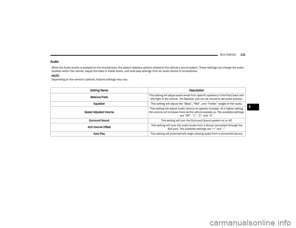
Audio
When the Audio button is pressed on the touchscreen, the system displays options related to the vehicle’s sound system. These settings can change the audio
location within the vehicle, adjust the bass or treble levels, and auto-play settings from an audio device or smartphone.
NOTE:Depending on the vehicle’s options, feature settings may vary.
Setting Name Description
Balance/Fade
This setting will adjust audio levels from specific speakers in the front/back and
left/right of the vehicle. The Speaker icon can be moved to set audio location.
Equalizer This setting will adjust the “Bass”, “Mid”, and “Treble” ranges of the audio.
Speed Adjusted Volume This setting will adjust audio volume as speeds increase. At a higher setting,
the volume will increase more as the vehicle speeds up. The available settings are “Off”, “1”, “2”, and “3”.
Surround Sound This setting will turn the Surround Sound system on or off.
AUX Volume Offset This setting will tune the audio levels from a device connected through the
AUX port. The available settings are “+” and “-”.
Auto Play This setting will automatically begin playing audio from a connected device.
5
21_LA_OM_EN_USC_t.book Page 131
Page 134 of 328
132MULTIMEDIA
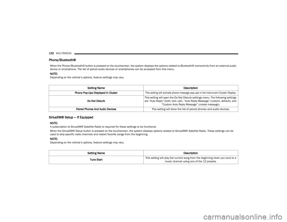
Phone/Bluetooth®
SiriusXM® Setup — If Equipped
When the Phone/Bluetooth® button is pressed on the touchscreen, the system displays the options related to Bluetooth® connectivity from an external audio
device or smartphone. The list of paired audio devices or smartphones can be accessed from this menu.
NOTE:Depending on the vehicle’s options, feature settings may vary.
Setting Name Description
Phone Pop-Ups Displayed In Cluster
This setting will activate phone message pop-ups in the Instrument Cluster Display.
Do Not Disturb This setting will open the Do Not Disturb settings menu. The following settings
are “Auto Reply” (both, text, call), “Auto Reply Message” (custom, default), and
“Custom Auto Reply Message” (create message).
Paired Phones And Audio Devices This setting will show the list of paired phones and audio devices.
NOTE:A subscription to SiriusXM® Satellite Radio is required for these settings to be functional.
When the SiriusXM® Setup button is pressed on the touchscreen, the system displays options related to SiriusXM® Satellite Radio. These settings can be
used to skip specific radio channels and restart favorite songs from the beginning.
NOTE:Depending on the vehicle’s options, feature settings may vary.
Setting Name Description
Tune StartThis setting will play the current song from the beginning when you tune to a
music channel using one of the 12 presets.
21_LA_OM_EN_USC_t.book Page 132