fuse DODGE CHALLENGER 2021 Owners Manual
[x] Cancel search | Manufacturer: DODGE, Model Year: 2021, Model line: CHALLENGER, Model: DODGE CHALLENGER 2021Pages: 328, PDF Size: 15 MB
Page 8 of 328
6
JUMP STARTING .................................................. 238 Preparations For Jump Start......................... 239Jump Starting Procedure .............................. 240
IF YOUR ENGINE OVERHEATS ........................... 241
MANUAL PARK RELEASE — 8 – SPEED
TRANSMISSION .................................................. 241
FREEING A STUCK VEHICLE ............................... 243
TOWING A DISABLED VEHICLE .......................... 244 Rear-Wheel Drive (RWD) Models.................. 245
ENHANCED ACCIDENT RESPONSE SYSTEM
(EARS) .................................................................. 245
EVENT DATA RECORDER (EDR) ......................... 245
SERVICING AND MAINTENANCE
SCHEDULED SERVICING .................................... 246
3.6L And 5.7L Engines ................................. 246
ENGINE COMPARTMENT .................................... 251
3.6L Engine ................................................... 2515.7L Engine ................................................... 252Checking Oil Level ......................................... 253
Adding Washer Fluid ..................................... 253
Maintenance-Free Battery ............................ 254
Pressure Washing ......................................... 254 VEHICLE MAINTENANCE..................................... 254
Engine Oil ...................................................... 255
Engine Oil Filter ............................................. 256Engine Air Cleaner Filter .............................. 256Air Conditioner Maintenance ....................... 257
Accessory Drive Belt Inspection ................... 259Body Lubrication ........................................... 260Windshield Wiper Blades.............................. 260Exhaust System ............................................. 261Cooling System .............................................. 262
Brake System ............................................... 265
Clutch Hydraulic System — Manual
Transmission (If Equipped)........................... 266Manual Transmission — If Equipped............ 266
Automatic Transmission — If Equipped ....... 266
All Wheel Drive (AWD) — If Equipped .......... 267
Rear Axle ........................................................ 267Fuses.............................................................. 267
Bulb Replacement ........................................ 276 TIRES ..................................................................... 279
Tire Safety Information ................................ 279Tires — General Information ........................ 288Tire Types....................................................... 291Spare Tires — If Equipped ............................ 292
Wheel And Wheel Trim Care ........................ 294Snow Traction Devices.................................. 295Tire Rotation Recommendations ................. 296
DEPARTMENT OF TRANSPORTATION UNIFORM
TIRE QUALITY GRADES ...................................... 296
Treadwear...................................................... 297
Traction Grades ............................................. 297Temperature Grades..................................... 297
VEHICLE STORAGE .............................................. 298
BODYWORK .......................................................... 298 Protection From Atmospheric Agents .......... 298
Body And Underbody Maintenance ............. 298
Preserving The Bodywork ............................. 298
INTERIORS ........................................................... 299
Seats And Fabric Parts ................................. 299
Plastic And Coated Parts .............................. 299
Leather Surfaces........................................... 300
Glass Surfaces ............................................. 300
21_LA_OM_EN_USC_t.book Page 6
Page 56 of 328
54GETTING TO KNOW YOUR VEHICLE
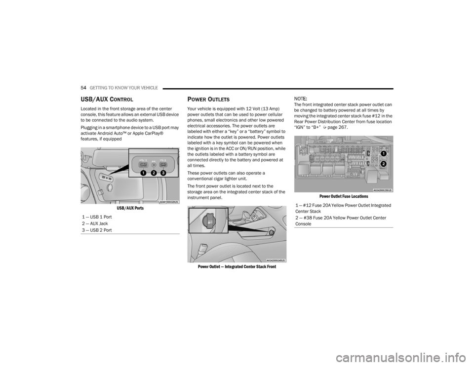
USB/AUX CONTROL
Located in the front storage area of the center
console, this feature allows an external USB device
to be connected to the audio system.
Plugging in a smartphone device to a USB port may
activate Android Auto™ or Apple CarPlay®
features, if equipped
USB/AUX Ports
POWER OUTLETS
Your vehicle is equipped with 12 Volt (13 Amp)
power outlets that can be used to power cellular
phones, small electronics and other low powered
electrical accessories. The power outlets are
labeled with either a “key” or a “battery” symbol to
indicate how the outlet is powered. Power outlets
labeled with a key symbol can be powered when
the ignition is in the ACC or ON/RUN position, while
the outlets labeled with a battery symbol are
connected directly to the battery and powered at
all times.
These power outlets can also operate a
conventional cigar lighter unit.
The front power outlet is located next to the
storage area on the integrated center stack of the
instrument panel.
Power Outlet — Integrated Center Stack Front
NOTE:The front integrated center stack power outlet can
be changed to battery powered at all times by
moving the integrated center stack fuse #12 in the
Rear Power Distribution Center from fuse location
“IGN” to “B+” Ú page 267.
Power Outlet Fuse Locations
1 — USB 1 Port
2 — AUX Jack
3 — USB 2 Port
1 — #12 Fuse 20A Yellow Power Outlet Integrated
Center Stack
2 — #38 Fuse 20A Yellow Power Outlet Center
Console
21_LA_OM_EN_USC_t.book Page 54
Page 57 of 328
GETTING TO KNOW YOUR VEHICLE55
(Continued)
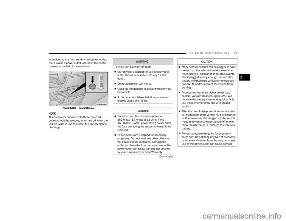
In addition to the front center stack power outlet,
there is also a power outlet located in the center
console to the left of the media hub.
Power Outlet — Center Console
NOTE:All accessories connected to these powered
outlets should be removed or turned off when the
vehicle is not in use to protect the battery against
discharge.
WARNING!
To avoid serious injury or death:
Only devices designed for use in this type of
outlet should be inserted into any 12 Volt
outlet.
Do not touch with wet hands.
Close the lid when not in use and while driving
the vehicle.
If this outlet is mishandled, it may cause an
electric shock and failure.
CAUTION!
Do not exceed the maximum power of
160 Watts (13 Amps) at 12 Volts. If the
160 Watt (13 Amp) power rating is exceeded
the fuse protecting the system will need to be
replaced.
Power outlets are designed for accessory
plugs only. Do not insert any other object in
the power outlets as this will damage the
outlet and blow the fuse. Improper use of the
power outlet can cause damage not covered
by your New Vehicle Limited Warranty.
Many accessories that can be plugged in draw
power from the vehicle's battery, even when
not in use (i.e., cellular phones, etc.). Eventu -
ally, if plugged in long enough, the vehicle's
battery will discharge sufficiently to degrade
battery life and/or prevent the engine from
starting.
Accessories that draw higher power (i.e.,
coolers, vacuum cleaners, lights, etc.), will
degrade the battery even more quickly. Only
use these intermittently and with greater
caution.
After the use of high power draw accessories,
or long periods of the vehicle not being started
(with accessories still plugged in), the vehicle
must be driven a sufficient length of time to
allow the alternator to recharge the vehicle's
battery.
Power outlets are designed for accessory
plugs only. Do not hang any type of accessory
or accessory bracket from the plug. Improper
use of the power outlet can cause damage.
CAUTION!
2
21_LA_OM_EN_USC_t.book Page 55
Page 241 of 328
IN CASE OF EMERGENCY239
NOTE:
When using a portable battery booster pack, follow the
manufacturer's operating instructions and precautions.
PREPARATIONS FOR JUMP START
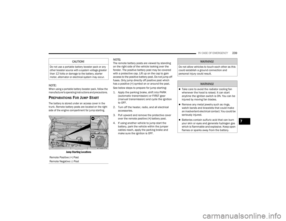
The battery is stored under an access cover in the
trunk. Remote battery posts are located on the right
side of the engine compartment for jump starting.
Jump Starting Locations
NOTE:The remote battery posts are viewed by standing
on the right side of the vehicle looking over the
fender. The positive battery post may be covered
with a protective cap. Lift up on the cap to gain
access to the positive battery post. Do not jump off
fuses. Only jump directly off positive post which
has a positive (+) symbol on or around the post.
See below steps to prepare for jump starting:
1. Apply the parking brake, shift into PARK (automatic transmission) or FIRST gear
(manual transmission) and cycle the ignition
to OFF.
2. Turn off the heater, radio, and all electrical accessories.
3. Pull upward and remove the protective cover over the remote positive (+) battery post.
4. If using another vehicle to jump start the battery, park the vehicle within the jumper
cables reach, apply the parking brake and
make sure the ignition is OFF.CAUTION!
Do not use a portable battery booster pack or any
other booster source with a system voltage greater
than 12 Volts or damage to the battery, starter
motor, alternator or electrical system may occur.
Remote Positive (+) Post
Remote Negative (-) Post
WARNING!
Do not allow vehicles to touch each other as this
could establish a ground connection and
personal injury could result.
WARNING!
Take care to avoid the radiator cooling fan
whenever the hood is raised. It can start
anytime the ignition switch is ON. You can be
injured by moving fan blades.
Remove any metal jewelry such as rings,
watch bands and bracelets that could make
an inadvertent electrical contact. You could be
seriously injured.
Batteries contain sulfuric acid that can burn
your skin or eyes and generate hydrogen gas
which is flammable and explosive. Keep open
flames or sparks away from the battery.7
21_LA_OM_EN_USC_t.book Page 239
Page 242 of 328
240IN CASE OF EMERGENCY
JUMP STARTING PROCEDURE
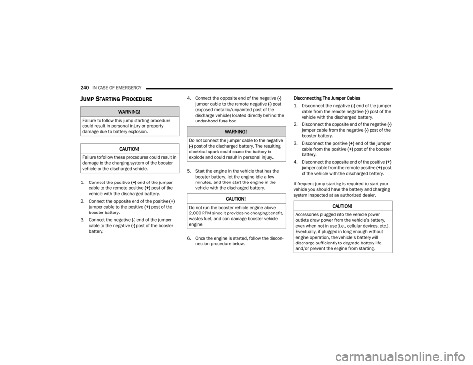
1. Connect the positive
(+) end of the jumper
cable to the remote positive (+)
post of the
vehicle with the discharged battery.
2. Connect the opposite end of the positive (+)
jumper cable to the positive (+) post of the
booster battery.
3. Connect the negative (-) end of the jumper
cable to the negative (-) post of the booster
battery. 4. Connect the opposite end of the negative
(-)
jumper cable to the remote negative (-) post
(exposed metallic/unpainted post of the
discharge vehicle) located directly behind the
under-hood fuse box.
5. Start the engine in the vehicle that has the booster battery, let the engine idle a few
minutes, and then start the engine in the
vehicle with the discharged battery.
6. Once the engine is started, follow the discon -
nection procedure below. Disconnecting The Jumper Cables
1. Disconnect the negative
(-) end of the jumper
cable from the remote negative (-)
post of the
vehicle with the discharged battery.
2. Disconnect the opposite end of the negative (-)
jumper cable from the negative (-) post of the
booster battery.
3. Disconnect the positive (+) end of the jumper
cable from the positive (+) post of the booster
battery.
4. Disconnect the opposite end of the positive (+)
jumper cable from the remote positive (+) post
of the vehicle with the discharged battery.
If frequent jump starting is required to start your
vehicle you should have the battery and charging
system inspected at an authorized dealer.
WARNING!
Failure to follow this jump starting procedure
could result in personal injury or property
damage due to battery explosion.
CAUTION!
Failure to follow these procedures could result in
damage to the charging system of the booster
vehicle or the discharged vehicle.
WARNING!
Do not connect the jumper cable to the negative
(-) post of the discharged battery. The resulting
electrical spark could cause the battery to
explode and could result in personal injury..
CAUTION!
Do not run the booster vehicle engine above
2,000 RPM since it provides no charging benefit,
wastes fuel, and can damage booster vehicle
engine.CAUTION!
Accessories plugged into the vehicle power
outlets draw power from the vehicle’s battery,
even when not in use (i.e., cellular devices, etc.).
Eventually, if plugged in long enough without
engine operation, the vehicle’s battery will
discharge sufficiently to degrade battery life
and/or prevent the engine from starting.
21_LA_OM_EN_USC_t.book Page 240
Page 253 of 328
SERVICING AND MAINTENANCE251
ENGINE COMPARTMENT
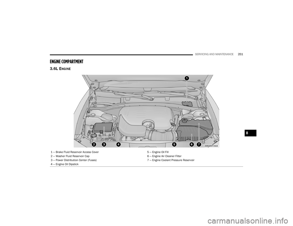
3.6L ENGINE
1 — Brake Fluid Reservoir Access Cover 5 — Engine Oil Fill
2 — Washer Fluid Reservoir Cap 6 — Engine Air Cleaner Filter
3 — Power Distribution Center (Fuses) 7 — Engine Coolant Pressure Reservoir
4 — Engine Oil Dipstick
8
21_LA_OM_EN_USC_t.book Page 251
Page 254 of 328
252SERVICING AND MAINTENANCE
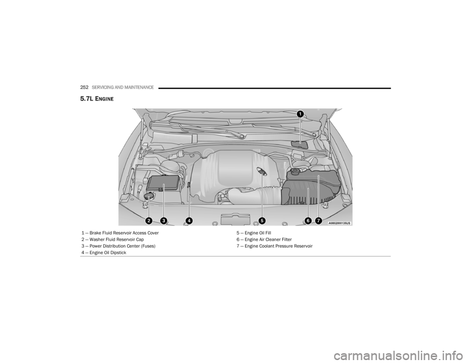
5.7L ENGINE
1 — Brake Fluid Reservoir Access Cover 5 — Engine Oil Fill
2 — Washer Fluid Reservoir Cap 6 — Engine Air Cleaner Filter
3 — Power Distribution Center (Fuses) 7 — Engine Coolant Pressure Reservoir
4 — Engine Oil Dipstick
21_LA_OM_EN_USC_t.book Page 252
Page 255 of 328
SERVICING AND MAINTENANCE253
(Continued)
CHECKING OIL LEVEL
To ensure proper engine lubrication, the engine oil
must be maintained at the correct level. Check the
oil level at regular intervals, such as every fuel
stop. The best time to check the engine oil level is
about ten minutes after a fully warmed up engine
is shut off.
Checking the oil while the vehicle is on level ground
will improve the accuracy of the oil level readings.
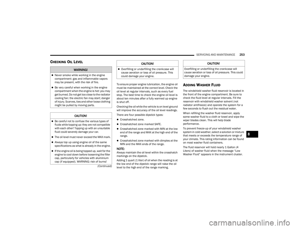
There are four possible dipstick types:
Crosshatched zone.
Crosshatched zone marked SAFE.
Crosshatched zone marked with MIN at the low
end of the range and MAX at the high end of the
range.
Crosshatched zone marked with dimples at the
MIN and the MAX ends of the range.
NOTE:Always maintain the oil level within the crosshatch
markings on the dipstick.
Adding 1 quart (1 liter) of oil when the reading is at
the low end of the dipstick range will raise the oil
level to the high end of the range marking.
ADDING WASHER FLUID
The windshield washer fluid reservoir is located in
the front of the engine compartment. Be sure to
check the fluid level at regular intervals. Fill the
reservoir with windshield washer solvent (not
radiator antifreeze) and operate the system for a
few seconds to flush out the residual water.
When refilling the washer fluid reservoir, apply
some washer fluid to a cloth or towel and wipe the
wiper blades clean. This will help blade
performance.
To prevent freeze-up of your windshield washer
system in cold weather, select a solution or mixture
that meets or exceeds the temperature range of
your climate. This rating information can be found
on most washer fluid containers.
The fluid reservoir will hold nearly 1 Gallon (4
Liters) of washer fluid when the message “Low
Washer Fluid” appears in the instrument cluster.
WARNING!
Never smoke while working in the engine
compartment: gas and inflammable vapors
may be present, with the risk of fire.
Be very careful when working in the engine
compartment when the engine is hot: you may
get burned. Do not get too close to the radiator
cooling fan: the electric fan may start; danger
of injury. Scarves, ties and other loose clothing
might be pulled by moving parts.
CAUTION!
Be careful not to confuse the various types of
fluids while topping up: they are not compatible
with each other! Topping up with an unsuitable
fluid could severely damage your car.
The oil level must never exceed the MAX mark.
Always top up using engine oil of the same
specifications as what is already in the engine.
If the engine oil is being topped up, wait for the
engine to cool down before loosening the filler
cap, particularly for vehicles with aluminium
cap (if equipped). WARNING: risk of burns!
Overfilling or underfilling the crankcase will
cause aeration or loss of oil pressure. This
could damage your engine.
CAUTION!CAUTION!
Overfilling or underfilling the crankcase will
cause aeration or loss of oil pressure. This could
damage your engine.
8
21_LA_OM_EN_USC_t.book Page 253
Page 269 of 328
SERVICING AND MAINTENANCE267
(Continued)
Fluid And Filter Changes
Under normal operating conditions, the fluid
installed at the factory will provide satisfactory
lubrication for the life of the vehicle.
Routine fluid and filter changes are not required.
However, change the fluid and filter if the fluid
becomes contaminated (with water, etc.), or if the
transmission is disassembled for any reason.
Selection Of Lubricant
It is important to use the proper transmission fluid
to ensure optimum transmission performance and
life. Use only the manufacturer's specified
transmission fluid Ú page 306. It is important to
maintain the transmission fluid at the correct level
using the recommended fluid.
NOTE:No chemical flushes should be used in any trans -
mission; only the approved lubricant should be
used.
ALL WHEEL DRIVE (AWD) —
I
F EQUIPPED
The All Wheel Drive system consists of a transfer
case and front differential. The exterior surface of
these components should be inspected for
evidence of fluid leaks. Confirmed leaks should be
repaired as soon as possible.
The transfer case fluid fill/inspection plug is
located in the middle of the rear housing. To
inspect the transfer case fluid level, remove the
fill/inspection plug. The fluid level should be even
with the bottom of the hole. Use this plug to add
fluid as required.
The front differential fill plug is located on the outer
cover near the half shaft attachment. To inspect
the differential fluid level, remove the fill plug. The
fluid level should be even with or slightly below the
bottom of the hole.
Fluid Changes
For the proper maintenance intervals Úpage 246.
REAR AXLE
Fluid Level Check
Checking the fluid level while the vehicle is on level
ground and has been stationary for 15 minutes will
improve the accuracy of the fluid level reading. Check the fluid level by removing the fill plug on the
axle. The fluid level should be 1-2.5 mm below the
fill plug. Add fluid, if necessary, to maintain the
proper level Ú
page 306.
Change Axle Fluid
For the proper maintenance intervals Úpage 246.
FUSES
General Information
CAUTION!
Using a transmission fluid other than the
manufacturer’s recommended fluid may cause
deterioration in transmission shift quality and/or
torque converter shudder Ú page 306.
WARNING!
When replacing a blown fuse, always use an
appropriate replacement fuse with the same
amp rating as the original fuse. Never replace
a fuse with another fuse of higher amp rating.
Never replace a blown fuse with metal wires or
any other material. Do not place a fuse inside
a circuit breaker cavity or vice versa. Failure to
use proper fuses may result in serious
personal injury, fire and/or property damage.
Before replacing a fuse, make sure that the
ignition is off and that all the other services
are switched off and/or disengaged.
If the replaced fuse blows again, contact an
authorized dealer.
8
21_LA_OM_EN_USC_t.book Page 267
Page 270 of 328
268SERVICING AND MAINTENANCE
The fuses protect electrical systems against
excessive current.
When a device does not work, you must check the
fuse element inside the blade fuse for a break/
melt.
Also, please be aware that when using power
outlets for extended periods of time with the
engine off may result in vehicle battery discharge.
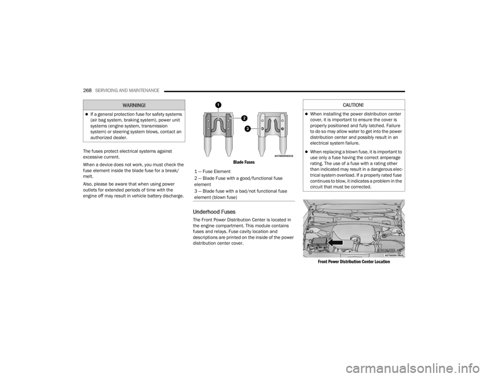
Blade Fuses
Underhood Fuses
The Front Power Distribution Center is located in
the engine compartment. This module contains
fuses and relays. Fuse cavity location and
descriptions are printed on the inside of the power
distribution center cover.
Front Power Distribution Center Location
If a general protection fuse for safety systems
(air bag system, braking system), power unit
systems (engine system, transmission
system) or steering system blows, contact an
authorized dealer.
WARNING!
1 — Fuse Element
2 — Blade Fuse with a good/functional fuse
element
3 — Blade fuse with a bad/not functional fuse
element (blown fuse)
CAUTION!
When installing the power distribution center
cover, it is important to ensure the cover is
properly positioned and fully latched. Failure
to do so may allow water to get into the power
distribution center and possibly result in an
electrical system failure.
When replacing a blown fuse, it is important to
use only a fuse having the correct amperage
rating. The use of a fuse with a rating other
than indicated may result in a dangerous elec-
trical system overload. If a properly rated fuse
continues to blow, it indicates a problem in the
circuit that must be corrected.
21_LA_OM_EN_USC_t.book Page 268