length DODGE CHALLENGER 2021 Owners Manual
[x] Cancel search | Manufacturer: DODGE, Model Year: 2021, Model line: CHALLENGER, Model: DODGE CHALLENGER 2021Pages: 328, PDF Size: 15 MB
Page 26 of 328
24GETTING TO KNOW YOUR VEHICLE
To Lock The Vehicle’s Doors:
With one of the vehicle’s Passive Entry key fobs
within 5 ft (1.5 m) of either door handle, pushing
the Passive Entry lock button will lock both doors.
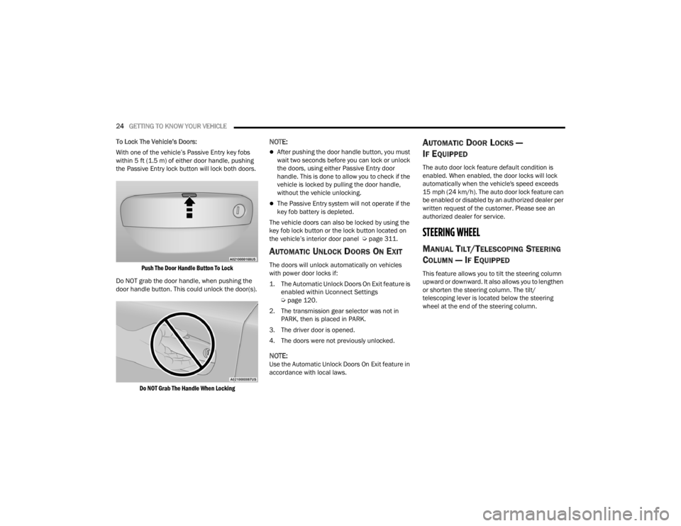
Push The Door Handle Button To Lock
Do NOT grab the door handle, when pushing the
door handle button. This could unlock the door(s).
Do NOT Grab The Handle When Locking
NOTE:
After pushing the door handle button, you must
wait two seconds before you can lock or unlock
the doors, using either Passive Entry door
handle. This is done to allow you to check if the
vehicle is locked by pulling the door handle,
without the vehicle unlocking.
The Passive Entry system will not operate if the
key fob battery is depleted.
The vehicle doors can also be locked by using the
key fob lock button or the lock button located on
the vehicle’s interior door panel Ú page 311.
AUTOMATIC UNLOCK DOORS ON EXIT
The doors will unlock automatically on vehicles
with power door locks if:
1. The Automatic Unlock Doors On Exit feature is
enabled within Uconnect Settings
Ú
page 120.
2. The transmission gear selector was not in PARK, then is placed in PARK.
3. The driver door is opened.
4. The doors were not previously unlocked.
NOTE:Use the Automatic Unlock Doors On Exit feature in
accordance with local laws.
AUTOMATIC DOOR LOCKS —
I
F EQUIPPED
The auto door lock feature default condition is
enabled. When enabled, the door locks will lock
automatically when the vehicle's speed exceeds
15 mph (24 km/h). The auto door lock feature can
be enabled or disabled by an authorized dealer per
written request of the customer. Please see an
authorized dealer for service.
STEERING WHEEL
MANUAL TILT/TELESCOPING STEERING
C
OLUMN — IF EQUIPPED
This feature allows you to tilt the steering column
upward or downward. It also allows you to lengthen
or shorten the steering column. The tilt/
telescoping lever is located below the steering
wheel at the end of the steering column.
21_LA_OM_EN_USC_t.book Page 24
Page 27 of 328
GETTING TO KNOW YOUR VEHICLE25
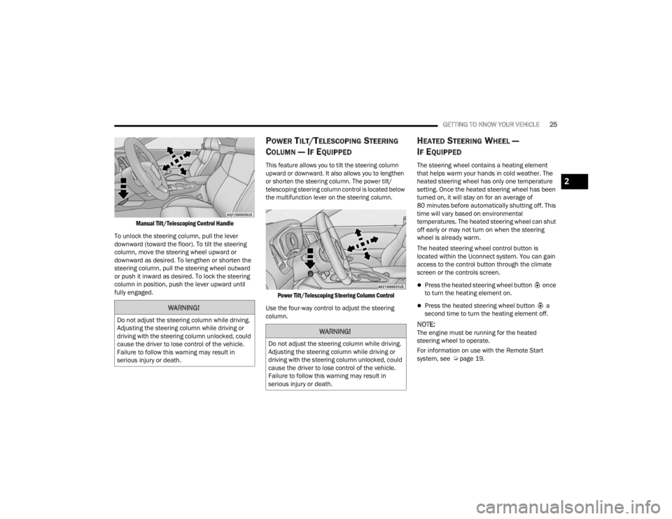
Manual Tilt/Telescoping Control Handle
To unlock the steering column, pull the lever
downward (toward the floor). To tilt the steering
column, move the steering wheel upward or
downward as desired. To lengthen or shorten the
steering column, pull the steering wheel outward
or push it inward as desired. To lock the steering
column in position, push the lever upward until
fully engaged.
POWER TILT/TELESCOPING STEERING
C
OLUMN — IF EQUIPPED
This feature allows you to tilt the steering column
upward or downward. It also allows you to lengthen
or shorten the steering column. The power tilt/
telescoping steering column control is located below
the multifunction lever on the steering column.
Power Tilt/Telescoping Steering Column Control
Use the four-way control to adjust the steering
column.
HEATED STEERING WHEEL —
I
F EQUIPPED
The steering wheel contains a heating element
that helps warm your hands in cold weather. The
heated steering wheel has only one temperature
setting. Once the heated steering wheel has been
turned on, it will stay on for an average of
80 minutes before automatically shutting off. This
time will vary based on environmental
temperatures. The heated steering wheel can shut
off early or may not turn on when the steering
wheel is already warm.
The heated steering wheel control button is
located within the Uconnect system. You can gain
access to the control button through the climate
screen or the controls screen.
Press the heated steering wheel button once
to turn the heating element on.
Press the heated steering wheel button a
second time to turn the heating element off.
NOTE:The engine must be running for the heated
steering wheel to operate.
For information on use with the Remote Start
system, see Ú page 19.
WARNING!
Do not adjust the steering column while driving.
Adjusting the steering column while driving or
driving with the steering column unlocked, could
cause the driver to lose control of the vehicle.
Failure to follow this warning may result in
serious injury or death.
WARNING!
Do not adjust the steering column while driving.
Adjusting the steering column while driving or
driving with the steering column unlocked, could
cause the driver to lose control of the vehicle.
Failure to follow this warning may result in
serious injury or death.
2
21_LA_OM_EN_USC_t.book Page 25
Page 57 of 328
GETTING TO KNOW YOUR VEHICLE55
(Continued)
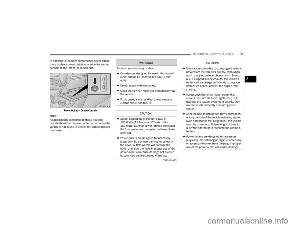
In addition to the front center stack power outlet,
there is also a power outlet located in the center
console to the left of the media hub.
Power Outlet — Center Console
NOTE:All accessories connected to these powered
outlets should be removed or turned off when the
vehicle is not in use to protect the battery against
discharge.
WARNING!
To avoid serious injury or death:
Only devices designed for use in this type of
outlet should be inserted into any 12 Volt
outlet.
Do not touch with wet hands.
Close the lid when not in use and while driving
the vehicle.
If this outlet is mishandled, it may cause an
electric shock and failure.
CAUTION!
Do not exceed the maximum power of
160 Watts (13 Amps) at 12 Volts. If the
160 Watt (13 Amp) power rating is exceeded
the fuse protecting the system will need to be
replaced.
Power outlets are designed for accessory
plugs only. Do not insert any other object in
the power outlets as this will damage the
outlet and blow the fuse. Improper use of the
power outlet can cause damage not covered
by your New Vehicle Limited Warranty.
Many accessories that can be plugged in draw
power from the vehicle's battery, even when
not in use (i.e., cellular phones, etc.). Eventu -
ally, if plugged in long enough, the vehicle's
battery will discharge sufficiently to degrade
battery life and/or prevent the engine from
starting.
Accessories that draw higher power (i.e.,
coolers, vacuum cleaners, lights, etc.), will
degrade the battery even more quickly. Only
use these intermittently and with greater
caution.
After the use of high power draw accessories,
or long periods of the vehicle not being started
(with accessories still plugged in), the vehicle
must be driven a sufficient length of time to
allow the alternator to recharge the vehicle's
battery.
Power outlets are designed for accessory
plugs only. Do not hang any type of accessory
or accessory bracket from the plug. Improper
use of the power outlet can cause damage.
CAUTION!
2
21_LA_OM_EN_USC_t.book Page 55
Page 125 of 328
MULTIMEDIA123
Voice
Clock
When the Voice button is pressed on the touchscreen, the system displays the options related to the vehicle’s Voice Recognition feature.
NOTE:Depending on the vehicle’s options, feature settings may vary.
Setting Name Description
Voice Response LengthThis setting will change the response length for the Voice Recognition system.
The “Brief” setting provides a shortened audio description from the system. The “Detailed” setting provides the full audio description from the system.
Show Command List This setting will allow you to turn the Command List on or off. The “Always”
setting will always show the Command List. The “With Help” setting will show
the Command List and provide a brief description of what the command does. The “Never” setting will turn the Command List off.
When the Clock button is pressed on the touchscreen, the system displays the different options related to the vehicle’s internal clock.
NOTE:Depending on the vehicle’s options, feature settings may vary.
Setting Name Description
Sync Time With GPSThis setting will sync the time to the GPS receiver in the system. The system
will control the time via the GPS location.
Time Format
This setting will allow you set the time format (AM/PM). Sync Time With GPS
must be off for this setting to be available. The “12 hrs” setting will set the time to a 12-hour format. The “24 hrs” setting will set the time to a 24-hour format.
5
21_LA_OM_EN_USC_t.book Page 123
Page 186 of 328
184SAFETY
AUXILIARY DRIVING SYSTEMS
BLIND SPOT MONITORING (BSM) —
I
F EQUIPPED
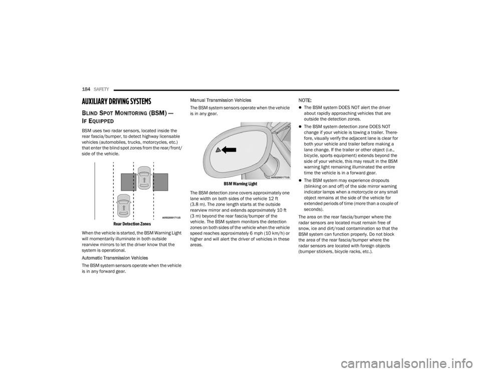
BSM uses two radar sensors, located inside the
rear fascia/bumper, to detect highway licensable
vehicles (automobiles, trucks, motorcycles, etc.)
that enter the blind spot zones from the rear/front/
side of the vehicle.
Rear Detection Zones
When the vehicle is started, the BSM Warning Light
will momentarily illuminate in both outside
rearview mirrors to let the driver know that the
system is operational.
Automatic Transmission Vehicles
The BSM system sensors operate when the vehicle
is in any forward gear. Manual Transmission Vehicles
The BSM system sensors operate when the vehicle
is in any gear.
BSM Warning Light
The BSM detection zone covers approximately one
lane width on both sides of the vehicle 12 ft
(3.8 m). The zone length starts at the outside
rearview mirror and extends approximately 10 ft
(3 m) beyond the rear fascia/bumper of the
vehicle. The BSM system monitors the detection
zones on both sides of the vehicle when the vehicle
speed reaches approximately 6 mph (10 km/h) or
higher and will alert the driver of vehicles in these
areas.
NOTE:
The BSM system DOES NOT alert the driver
about rapidly approaching vehicles that are
outside the detection zones.
The BSM system detection zone DOES NOT
change if your vehicle is towing a trailer. There -
fore, visually verify the adjacent lane is clear for
both your vehicle and trailer before making a
lane change. If the trailer or other object (i.e.,
bicycle, sports equipment) extends beyond the
side of your vehicle, this may result in the BSM
warning light remaining illuminated the entire
time the vehicle is in a forward gear.
The BSM system may experience dropouts
(blinking on and off) of the side mirror warning
indicator lamps when a motorcycle or any small
object remains at the side of the vehicle for
extended periods of time (more than a couple of
seconds).
The area on the rear fascia/bumper where the
radar sensors are located must remain free of
snow, ice and dirt/road contamination so that the
BSM system can function properly. Do not block
the area of the rear fascia/bumper where the
radar sensors are located with foreign objects
(bumper stickers, bicycle racks, etc.).
21_LA_OM_EN_USC_t.book Page 184
Page 258 of 328
256SERVICING AND MAINTENANCE
Shaker Hood Air Filter Cleaning
1. Remove the air filter from the intake and set the filter clamp aside.
2. Measure the length of the filter media.
3. Fill a bucket with warm clean water to the depth matching the filter media measurement
and add a mild household detergent or air
filter cleaning solution.
4. Without allowing the solution to flow back into the inside of the air filter, submerge the filter media in
to the water and let it soak for ten minutes.
5. Empty the bucket filled with dirty water and repeat steps 3 and 4.
6. Refill the bucket with clean warm water and rinse the filter by rotating the filter.
NOTE:The water should be clean with no signs of dirt in
the bucket.
7. Allow the filter to air dry. Reinstall the filter on the intake system once it is dry.
Shaker Hood Removal And Cleaning
1. Remove the four nuts with the Shaker tool located in glove compartment.
2. Lift off the upper scoop.
NOTE:Be sure to clean off all debris around or inside of
the Shaker assembly. 3. Using a water and mild detergent clean the
following locations:
The water drain slot located at the front
forward edge of the Shaker assembly.
The seals attached to the scoop and air box.
Lower water drains located in the lower
Shaker assembly and air box as well as the
hood interface areas for the seals. Apply
Mopar® Leather, Rubber & Vinyl Protectant
after cleaning the seals.
4. Reinstall Shaker assembly.
Materials Added To Engine Oil
The manufacturer strongly recommends against
the addition of any additives (other than leak
detection dyes) to the engine oil. Engine oil is an
engineered product and its performance may be
impaired by supplemental additives.
Disposing Of Used Engine Oil And Oil
Filters
Care should be taken in disposing of used engine
oil and oil filters from your vehicle. Used oil and oil
filters, indiscriminately discarded, can present a
problem to the environment. Contact an
authorized dealer, service station or governmental
agency for advice on how and where used oil and
oil filters can be safely discarded in your area.
ENGINE OIL FILTER
The engine oil filter should be replaced with a new
filter at every engine oil change.
Engine Oil Filter Selection
A full-flow type disposable oil filter should be used
for replacement. The quality of replacement filters
varies considerably. Only high quality Mopar®
certified filters should be used.
ENGINE AIR CLEANER FILTER
For the proper maintenance intervals Úpage 247.
Engine Air Cleaner Filter Selection
The quality of replacement filters varies
considerably. Only high quality Mopar® certified
filters should be used.
WARNING!
The air induction system (air cleaner, hoses,
etc.) can provide a measure of protection in the
case of engine backfire. Do not remove the air
induction system (air cleaner, hoses, etc.) unless
such removal is necessary for repair or
maintenance. Make sure that no one is near the
engine compartment before starting the vehicle
with the air induction system (air cleaner, hoses,
etc.) removed. Failure to do so can result in
serious personal injury.
21_LA_OM_EN_USC_t.book Page 256