torque DODGE CHALLENGER 2021 Owners Manual
[x] Cancel search | Manufacturer: DODGE, Model Year: 2021, Model line: CHALLENGER, Model: DODGE CHALLENGER 2021Pages: 328, PDF Size: 15 MB
Page 9 of 328
7
TECHNICAL SPECIFICATIONS
VEHICLE IDENTIFICATION NUMBER (VIN)......... 301
BRAKE SYSTEM .................................................. 301
WHEEL AND TIRE TORQUE SPECIFICATIONS .. 301Torque Specifications ................................... 301
FUEL REQUIREMENTS ........................................ 302
3.6L Engine.................................................... 302
5.7L Engine (With Automatic Transmission).. 302
5.7L Engine (With Manual Transmission).... 303Reformulated Gasoline ................................ 303
Materials Added To Fuel ............................... 303
Gasoline/Oxygenate Blends ......................... 303
Do Not Use E-85 In Non-Flex Fuel Vehicles ... 304
CNG And LP Fuel System Modifications ...... 304
Methylcyclopentadienyl Manganese
Tricarbonyl (MMT) In Gasoline...................... 304Fuel System Cautions ................................... 304 FLUID CAPACITIES .............................................. 305
ENGINE FLUIDS AND LUBRICANTS................... 306
CHASSIS FLUIDS AND LUBRICANTS ................ 307
CUSTOMER ASSISTANCE
SUGGESTIONS FOR OBTAINING SERVICE FOR
YOUR VEHICLE .................................................... 308
Prepare For The Appointment ...................... 308Prepare A List ................................................ 308Be Reasonable With Requests..................... 308
IF YOU NEED ASSISTANCE ................................. 308
FCA US LLC Customer Center....................... 308
FCA Canada Inc. Customer Center............... 308
Mexico ............................................................ 309
Puerto Rico And US Virgin Islands................ 309
Customer Assistance For The Hearing
Or Speech Impaired(TDD/TTY) ..................... 309
Service Contract ........................................... 309 WARRANTY INFORMATION ................................ 310
MOPAR® PARTS ................................................. 310
REPORTING SAFETY DEFECTS .......................... 310
In The 50 United States And
Washington, D.C............................................ 310
In Canada ...................................................... 310
PUBLICATION ORDER FORMS .......................... 311
GENERAL INFORMATION.................................... 311
21_LA_OM_EN_USC_t.book Page 7
Page 92 of 328
90STARTING AND OPERATING
REVERSE (R)
This range is for moving the vehicle backward.
Shift into REVERSE only after the vehicle has come
to a complete stop.
NEUTRAL (N)
Use this range when the vehicle is standing for
prolonged periods with the engine running. Apply
the parking brake and shift the transmission into
PARK if you must exit the vehicle.
DRIVE (D)
This range should be used for most city and
highway driving. It provides the smoothest upshifts
and downshifts, and the best fuel economy. The
transmission automatically upshifts through all
forward gears.
When frequent transmission shifting occurs (such
as when operating the vehicle under heavy loading
conditions, in hilly terrain, traveling into strong
head winds, or while towing a heavy trailer), use
the AutoStick shift control to select a lower gear
Úpage 91. Under these conditions, using a lower
gear will improve performance and extend
transmission life by reducing excessive shifting
and heat build-up.
During cold temperatures, transmission operation
may be modified depending on engine and
transmission temperature as well as vehicle
speed. This feature improves warm up time of the
engine and transmission to achieve maximum
efficiency. Engagement of the torque converter
clutch is inhibited until the transmission fluid is
warm. Normal operation will resume once the
transmission temperature has risen to a suitable
level.
MANUAL (M)
The MANUAL (M, +/-) position (beside the DRIVE
position) enables full manual control of
transmission shifting (also known as AutoStick
mode Ú page 91. Toggling the gear selector
forward (-) or rearward (+) while in the MANUAL
(AutoStick) position will manually select the
transmission gear, and will display the current gear
in the instrument cluster as M1, M2, M3, etc.
Transmission Limp Home Mode
Transmission function is monitored electronically
for abnormal conditions. If a condition is detected
that could result in transmission damage,
Transmission Limp Home Mode is activated. In this
mode, the transmission may operate only in
certain gears, or may not shift at all. Vehicle
performance may be severely degraded and the
engine may stall. In some situations, the
transmission may not re-engage if the engine is
turned off and restarted. The Malfunction Indicator
Light (MIL) may be illuminated. A message in the
instrument cluster will inform the driver of the
more serious conditions, and indicate what actions
may be necessary.
In the event of a momentary problem, the
transmission can be reset to regain all forward
gears by performing the following steps:WARNING!
Do not coast in NEUTRAL and never turn off the
ignition to coast down a hill. These are unsafe
practices that limit your response to changing
traffic or road conditions. You might lose control
of the vehicle and have a collision.
CAUTION!
Towing the vehicle, coasting, or driving for any
other reason with the transmission in NEUTRAL
can cause severe transmission damage.
For Recreational Towing Ú page 117.
For Towing A Disabled Vehicle Ú page 244.
21_LA_OM_EN_USC_t.book Page 90
Page 169 of 328
MULTIMEDIA167
Gauge: Intake Air Temp
Gauge: Engine Torque
Gauge: Engine Power
Gauge: G-Force
Gauge: Steering Angle
Gauge: Current Gear
Gauge: Current Speed
Timer: 0–60 mph (0–100 km/h)
Timer: 0–100 mph (0–160 km/h)
Timer: 60 ft (20 m)
Timer: 330 ft (100 m)
Timer: 1/8 Mile (200 m)
Timer: 1000 ft (300 m)
Timer: 1/4 Mile (400 m)
Timer: Braking Distance
Timer: Reaction Time
Historical Data
The Historical Data feature allows you to view
information about your vehicle such as the VIN,
miles on the odometer, longitude and latitude
coordinates, and more. To activate the Historical Data feature on your
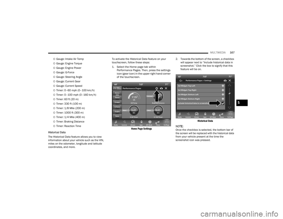
touchscreen, follow these steps:
1. Select the Home page tab within
Performance Pages. Then, press the settings
icon (gear icon) in the upper right hand corner
of the touchscreen.
Home Page Settings
2. Towards the bottom of the screen, a checkbox
will appear next to “Include historical data in
screenshot.” Click the box to signify that this
feature will be on.
Historical Data
NOTE:Once the checkbox is selected, the bottom bar of
the screen will be replaced with the historical data
from your vehicle present at the time the
screenshot icon was pressed.
5
21_LA_OM_EN_USC_t.book Page 167
Page 174 of 328
172MULTIMEDIA
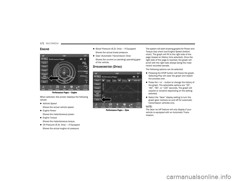
ENGINE
Performance Pages — Engine
When selected, this screen displays the following
values:
Vehicle Speed
Shows the actual vehicle speed.
Engine Power
Shows the instantaneous power.
Engine Torque
Shows the instantaneous torque.
Oil Pressure (6.4L Only) — If Equipped
Shows the actual engine oil pressure.
Boost Pressure (6.2L Only) — If Equipped
Shows the actual boost pressure.
Gear (Automatic Transmission Only)
Shows the current (or pending) operating gear
of the vehicle.
DYNAMOMETER (DYNO)
Performance Pages — Dyno
The system will start drawing graphs for Power and
Torque (top chart) and Engine Speed (bottom
chart). The graph will fill to the right side of the
page (based on History time selected). Once the
right side of the page is reached, the graph will
scroll with the right side always being the most
recent recorded sample.
The following options can be selected:
Pressing the STOP button will freeze the graph.
Selecting Play will clear the graph and restart
the process over.
Press the + or – button to change the history of
the graph. The selectable options are “30”,
“60”, “90”, or “120” seconds. The graph will
expand or constrict depending on the setting
selected.
Select the “Gear” display setting to turn the
graph gear markers on and off for automatic
transmission vehicles only.
NOTE:The Gear on/off feature will only display if your
vehicle is equipped with an Automatic Trans
-
mission.
21_LA_OM_EN_USC_t.book Page 172
Page 181 of 328
SAFETY179
If the ABS Warning Light is on, the brake system
should be serviced as soon as possible to restore
the benefits of Anti-Lock Brakes. If the ABS
Warning Light does not come on when the ignition
is placed in the ON/RUN mode, have the light
repaired as soon as possible.
ELECTRONIC BRAKE CONTROL (EBC)
S
YSTEM
Your vehicle is equipped with an advanced
Electronic Brake Control (EBC) system. This system
includes Anti-Lock Brake System (ABS), Brake
Assist System (BAS), Electronic Brake Force
Distribution (EBD), Electronic Roll Mitigation
(ERM), Electronic Stability Control (ESC), Hill Start
Assist (HSA), and Traction Control System (TCS).
These systems work together to enhance both
vehicle stability and control in various driving
conditions.
Your vehicle may also be equipped with Ready
Alert Braking (RAB) and Rain Brake Support (RBS).
Brake Assist System (BAS)
The BAS is designed to optimize the vehicle’s
braking capability during emergency braking
maneuvers. The system detects an emergency
braking situation by sensing the rate and amount
of brake application and then applies optimum
pressure to the brakes. This can help reduce
braking distances. The BAS complements the Anti-Lock Brake System (ABS). Applying the brakes
very quickly results in the best BAS assistance. To
receive the benefit of the system, you must apply
continuous braking pressure during the stopping
sequence (do not “pump” the brakes). Do not
reduce brake pedal pressure unless braking is no
longer desired. Once the brake pedal is released,
the BAS is deactivated.Brake System Warning Light
The red Brake System Warning Light will turn on
when the ignition is placed in the ON/RUN mode
and may stay on for as long as four seconds.
If the Brake System Warning Light remains on or
comes on while driving, it indicates that the brake
system is not functioning properly and that
immediate service is required. If the Brake System Warning Light does not come on when the ignition
is placed in the ON/RUN mode, have the light
repaired as soon as possible.
Electronic Brake Force Distribution (EBD)
EBD manages the distribution of the braking
torque between the front and rear axles by limiting
braking pressure to the rear axle. This is done to
prevent overslip of the rear wheels to avoid vehicle
instability, and to prevent the rear axle from
entering the Anti-Lock Brake System (ABS) before
the front axle.
Electronic Roll Mitigation (ERM)
ERM anticipates the potential for wheel lift by
monitoring the driver’s steering wheel input and
the speed of the vehicle. When ERM determines
that the rate of change of the steering wheel angle
and vehicle’s speed are sufficient to potentially
cause wheel lift, it then applies the appropriate
brake and may also reduce engine power to lessen
the chance that wheel lift will occur. ERM can only
reduce the chance of wheel lift occurring during
severe or evasive driving maneuvers; it cannot
prevent wheel lift due to other factors, such as
road conditions, leaving the roadway, or striking
objects or other vehicles.
NOTE:ERM is disabled any time the ESC is in “Full Off”
mode (if equipped). For a complete explanation of
the available ESC modes, see Ú
page 180.
WARNING!
The Brake Assist System (BAS) cannot prevent
the natural laws of physics from acting on the
vehicle, nor can it increase the traction afforded
by prevailing road conditions. BAS cannot
prevent collisions, including those resulting from
excessive speed in turns, driving on very slippery
surfaces, or hydroplaning. The capabilities of a
BAS-equipped vehicle must never be exploited in
a reckless or dangerous manner, which could
jeopardize the user's safety or the safety of
others.
6
21_LA_OM_EN_USC_t.book Page 179
Page 183 of 328
SAFETY181
(Continued)
ESC Operating Modes
Depending upon model and mode of operation, the
ESC system may have multiple operating modes.
ESC On
This is the normal operating mode for the ESC.
Whenever the vehicle is started, the ESC system
will be in this mode. This mode should be used for
most driving conditions. Alternate ESC modes
should only be used for specific reasons as noted
in the following paragraphs. Partial Off
This mode may be useful if the vehicle becomes
stuck. This mode may modify TCS and ESC
thresholds for activation, which allows for more
wheel spin than normally allowed.
To enter the “Partial Off” mode, momentarily push
the ESC OFF switch and the ESC OFF Indicator
Light will illuminate. To turn the ESC on again,
momentarily push the ESC OFF switch and the ESC
OFF Indicator Light will turn off.
NOTE:
For vehicles with multiple partial ESC modes,
the push and release of the switch will toggle
the ESC modes. Multiple attempts may be
required to return to "ESC On" mode.
Trailer Sway Control (TSC) is disabled when the
ESC system is in the “Partial Off” mode.
If Equipped — "ESC Sport" and "ESC Track" are
ESC “Partial Off” mode(s).
Full Off – If Equipped
This mode is intended for off-highway or off-road
use only and should not be used on any public
roadways. In this mode, TCS and ESC features are
turned off. To enter the “Full Off” mode, push and
hold the ESC OFF switch for five seconds while the
vehicle is stopped with the engine running. After
five seconds, a chime will sound, the ESC OFF
Indicator Light will illuminate, and the “ESC OFF”
message will display in the instrument cluster. To
turn ESC on again, momentarily push the ESC OFF
switch.Vehicle modifications, or failure to properly
maintain your vehicle, may change the
handling characteristics of your vehicle, and
may negatively affect the performance of the
ESC system. Changes to the steering system,
suspension, braking system, tire type and size
or wheel size may adversely affect ESC perfor -
mance. Improperly inflated and unevenly worn
tires may also degrade ESC performance. Any
vehicle modification or poor vehicle mainte -
nance that reduces the effectiveness of the
ESC system can increase the risk of loss of
vehicle control, vehicle rollover, personal
injury and death.
WARNING!
WARNING!
When in “Partial Off” mode, the TCS functionality
of ESC (except for the limited slip feature
described in the TCS section) has been disabled
and the ESC OFF Indicator Light will be
illuminated. When in “Partial Off” mode, the
engine power reduction feature of TCS is
disabled, and the enhanced vehicle stability
offered by the ESC system is reduced.
WARNING!
In the ESC “Full Off” mode, the engine torque
reduction and stability features are disabled.
Therefore, enhanced vehicle stability offered
by the ESC system is unavailable. In an emer -
gency evasive maneuver, the ESC system will
not engage to assist in maintaining stability.
ESC “Full Off” mode is intended for
off-highway or off-road use only.
6
21_LA_OM_EN_USC_t.book Page 181
Page 227 of 328
SAFETY225
PERIODIC SAFETY CHECKS YOU SHOULD
M
AKE OUTSIDE THE VEHICLE
Tires
Examine tires for excessive tread wear and uneven
wear patterns. Check for stones, nails, glass, or
other objects lodged in the tread or sidewall.
Inspect the tread for cuts and cracks. Inspect
sidewalls for cuts, cracks, and bulges. Check the
lug nuts/bolt torque for tightness. Check the tires
(including spare) for proper cold inflation pressure.
Lights
Have someone observe the operation of brake
lights and exterior lights while you work the
controls. Check turn signal and high beam
indicator lights on the instrument panel.
Door Latches
Check for proper closing, latching, and locking.
Fluid Leaks
Check area under the vehicle after overnight
parking for fuel, coolant, oil, or other fluid leaks.
Also, if gasoline fumes are detected or if fuel or
brake fluid leaks are suspected, the cause should
be located and corrected immediately.
EXHAUST GAS
The best protection against carbon monoxide entry
into the vehicle body is a properly maintained
engine exhaust system.
Whenever a change is noticed in the sound of the
exhaust system, when exhaust fumes can be
detected inside the vehicle, or when the underside
or rear of the vehicle is damaged, have an authorized dealer inspect the complete exhaust
system and adjacent body areas for broken,
damaged, deteriorated, or mispositioned parts.
Open seams or loose connections could permit
exhaust fumes to seep into the passenger
compartment. In addition, inspect the exhaust
system each time the vehicle is raised for
lubrication or oil change. Replace as required.
CARBON MONOXIDE WARNINGS
WARNING!
Exhaust gases can injure or kill. They contain
carbon monoxide (CO), which is colorless and
odorless. Breathing it can make you
unconscious and can eventually poison you. To
avoid breathing (CO), follow these safety tips:
Do not run the engine in a closed garage or in
confined areas any longer than needed to
move your vehicle in or out of the area.
If you are required to drive with the trunk/lift
-
gate/rear doors open, make sure that all
windows are closed and the climate control
BLOWER switch is set at high speed. DO NOT
use the recirculation mode.
If it is necessary to sit in a parked vehicle with
the engine running, adjust your heating or
cooling controls to force outside air into the
vehicle. Set the blower at high speed.
WARNING!
Carbon monoxide (CO) in exhaust gases is
deadly. Follow the precautions below to prevent
carbon monoxide poisoning:
Do not inhale exhaust gases. They contain
carbon monoxide, a colorless and odorless gas,
which can kill. Never run the engine in a closed
area, such as a garage, and never sit in a parked
vehicle with the engine running for an extended
period. If the vehicle is stopped in an open area
with the engine running for more than a short
period, adjust the ventilation system to force
fresh, outside air into the vehicle.
Guard against carbon monoxide with proper
maintenance. Have the exhaust system
inspected every time the vehicle is raised.
Have any abnormal conditions repaired
promptly. Until repaired, drive with all side
windows fully open.
6
21_LA_OM_EN_USC_t.book Page 225
Page 235 of 328
IN CASE OF EMERGENCY233
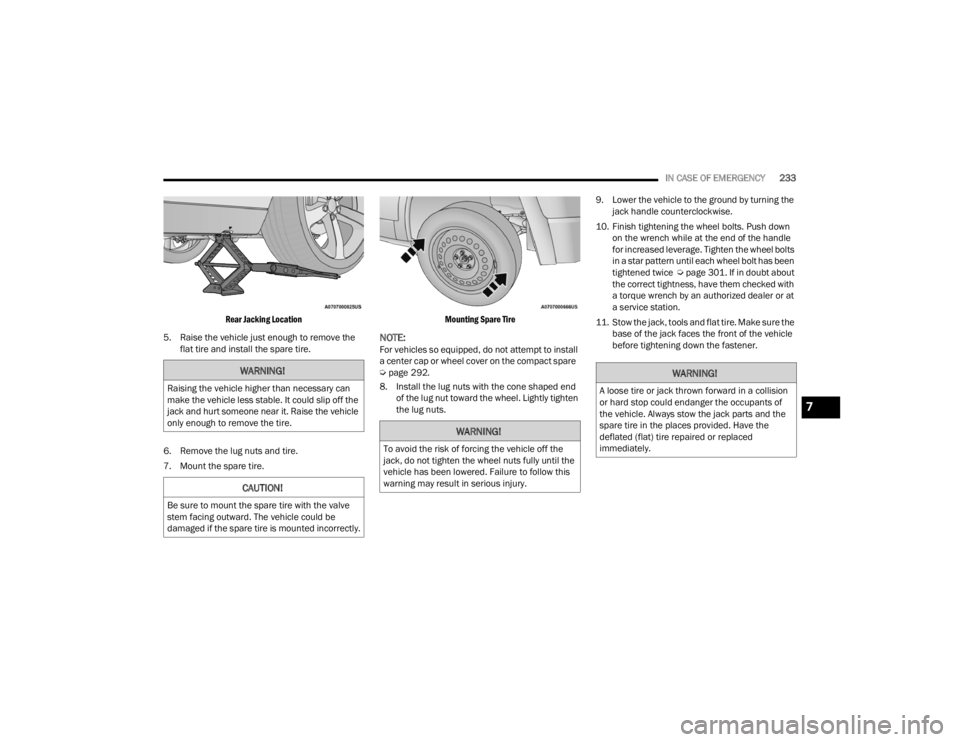
Rear Jacking Location
5. Raise the vehicle just enough to remove the flat tire and install the spare tire.
6. Remove the lug nuts and tire.
7. Mount the spare tire.
Mounting Spare Tire
NOTE:For vehicles so equipped, do not attempt to install
a center cap or wheel cover on the compact spare
Ú
page 292.
8. Install the lug nuts with the cone shaped end of the lug nut toward the wheel. Lightly tighten
the lug nuts. 9. Lower the vehicle to the ground by turning the
jack handle counterclockwise.
10. Finish tightening the wheel bolts. Push down on the wrench while at the end of the handle
for increased leverage. Tighten the wheel bolts
in a star pattern until each wheel bolt has been
tightened twice Úpage 301. If in doubt about
the correct tightness, have them checked with
a torque wrench by an authorized dealer or at
a service station.
11. Stow the jack, tools and flat tire. Make sure the base of the jack faces the front of the vehicle
before tightening down the fastener.
WARNING!
Raising the vehicle higher than necessary can
make the vehicle less stable. It could slip off the
jack and hurt someone near it. Raise the vehicle
only enough to remove the tire.
CAUTION!
Be sure to mount the spare tire with the valve
stem facing outward. The vehicle could be
damaged if the spare tire is mounted incorrectly.
WARNING!
To avoid the risk of forcing the vehicle off the
jack, do not tighten the wheel nuts fully until the
vehicle has been lowered. Failure to follow this
warning may result in serious injury.
WARNING!
A loose tire or jack thrown forward in a collision
or hard stop could endanger the occupants of
the vehicle. Always stow the jack parts and the
spare tire in the places provided. Have the
deflated (flat) tire repaired or replaced
immediately.
7
21_LA_OM_EN_USC_t.book Page 233
Page 269 of 328
SERVICING AND MAINTENANCE267
(Continued)
Fluid And Filter Changes
Under normal operating conditions, the fluid
installed at the factory will provide satisfactory
lubrication for the life of the vehicle.
Routine fluid and filter changes are not required.
However, change the fluid and filter if the fluid
becomes contaminated (with water, etc.), or if the
transmission is disassembled for any reason.
Selection Of Lubricant
It is important to use the proper transmission fluid
to ensure optimum transmission performance and
life. Use only the manufacturer's specified
transmission fluid Ú page 306. It is important to
maintain the transmission fluid at the correct level
using the recommended fluid.
NOTE:No chemical flushes should be used in any trans -
mission; only the approved lubricant should be
used.
ALL WHEEL DRIVE (AWD) —
I
F EQUIPPED
The All Wheel Drive system consists of a transfer
case and front differential. The exterior surface of
these components should be inspected for
evidence of fluid leaks. Confirmed leaks should be
repaired as soon as possible.
The transfer case fluid fill/inspection plug is
located in the middle of the rear housing. To
inspect the transfer case fluid level, remove the
fill/inspection plug. The fluid level should be even
with the bottom of the hole. Use this plug to add
fluid as required.
The front differential fill plug is located on the outer
cover near the half shaft attachment. To inspect
the differential fluid level, remove the fill plug. The
fluid level should be even with or slightly below the
bottom of the hole.
Fluid Changes
For the proper maintenance intervals Úpage 246.
REAR AXLE
Fluid Level Check
Checking the fluid level while the vehicle is on level
ground and has been stationary for 15 minutes will
improve the accuracy of the fluid level reading. Check the fluid level by removing the fill plug on the
axle. The fluid level should be 1-2.5 mm below the
fill plug. Add fluid, if necessary, to maintain the
proper level Ú
page 306.
Change Axle Fluid
For the proper maintenance intervals Úpage 246.
FUSES
General Information
CAUTION!
Using a transmission fluid other than the
manufacturer’s recommended fluid may cause
deterioration in transmission shift quality and/or
torque converter shudder Ú page 306.
WARNING!
When replacing a blown fuse, always use an
appropriate replacement fuse with the same
amp rating as the original fuse. Never replace
a fuse with another fuse of higher amp rating.
Never replace a blown fuse with metal wires or
any other material. Do not place a fuse inside
a circuit breaker cavity or vice versa. Failure to
use proper fuses may result in serious
personal injury, fire and/or property damage.
Before replacing a fuse, make sure that the
ignition is off and that all the other services
are switched off and/or disengaged.
If the replaced fuse blows again, contact an
authorized dealer.
8
21_LA_OM_EN_USC_t.book Page 267
Page 303 of 328
301
TECHNICAL SPECIFICATIONS
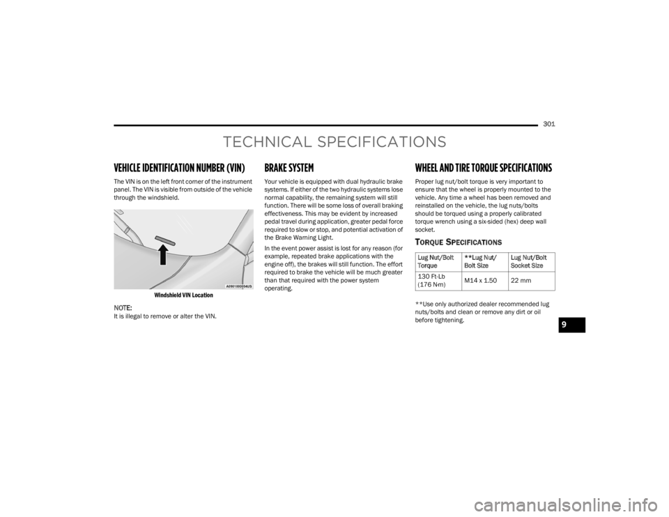
VEHICLE IDENTIFICATION NUMBER (VIN)
The VIN is on the left front corner of the instrument
panel. The VIN is visible from outside of the vehicle
through the windshield.
Windshield VIN Location
NOTE:It is illegal to remove or alter the VIN.
BRAKE SYSTEM
Your vehicle is equipped with dual hydraulic brake
systems. If either of the two hydraulic systems lose
normal capability, the remaining system will still
function. There will be some loss of overall braking
effectiveness. This may be evident by increased
pedal travel during application, greater pedal force
required to slow or stop, and potential activation of
the Brake Warning Light.
In the event power assist is lost for any reason (for
example, repeated brake applications with the
engine off), the brakes will still function. The effort
required to brake the vehicle will be much greater
than that required with the power system
operating.
WHEEL AND TIRE TORQUE SPECIFICATIONS
Proper lug nut/bolt torque is very important to
ensure that the wheel is properly mounted to the
vehicle. Any time a wheel has been removed and
reinstalled on the vehicle, the lug nuts/bolts
should be torqued using a properly calibrated
torque wrench using a six-sided (hex) deep wall
socket.
TORQUE SPECIFICATIONS
**Use only authorized dealer recommended lug
nuts/bolts and clean or remove any dirt or oil
before tightening.
Lug Nut/Bolt
Torque **Lug Nut/
Bolt SizeLug Nut/Bolt
Socket Size
130 Ft-Lb
(176 N·m) M14 x 1.50 22 mm
9
21_LA_OM_EN_USC_t.book Page 301