change key battery DODGE CHALLENGER SRT 2018 Owners Manual
[x] Cancel search | Manufacturer: DODGE, Model Year: 2018, Model line: CHALLENGER SRT, Model: DODGE CHALLENGER SRT 2018Pages: 486, PDF Size: 4.56 MB
Page 20 of 486
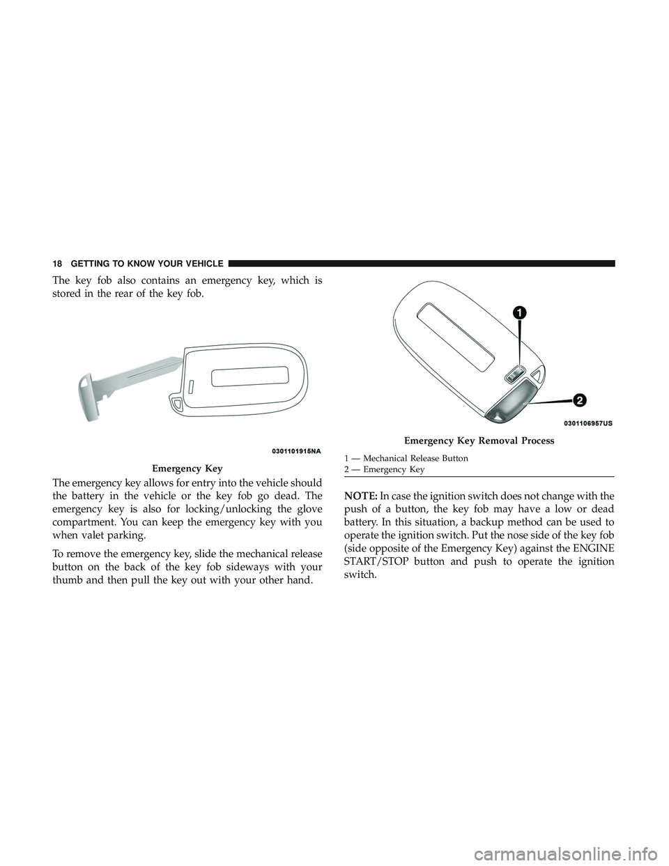
The key fob also contains an emergency key, which is
stored in the rear of the key fob.
The emergency key allows for entry into the vehicle should
the battery in the vehicle or the key fob go dead. The
emergency key is also for locking/unlocking the glove
compartment. You can keep the emergency key with you
when valet parking.
To remove the emergency key, slide the mechanical release
button on the back of the key fob sideways with your
thumb and then pull the key out with your other hand.NOTE:
In case the ignition switch does not change with the
push of a button, the key fob may have a low or dead
battery. In this situation, a backup method can be used to
operate the ignition switch. Put the nose side of the key fob
(side opposite of the Emergency Key) against the ENGINE
START/STOP button and push to operate the ignition
switch.
Emergency Key
Emergency Key Removal Process
1 — Mechanical Release Button
2 — Emergency Key
18 GETTING TO KNOW YOUR VEHICLE
Page 26 of 486
General Information
The following regulatory statement applies to all radio
frequency (RF) devices equipped in this vehicle:
This device complies with Part 15 of the FCC Rules and
with Industry Canada license-exempt RSS standard(s).
Operation is subject to the following two conditions:
1. This device may not cause harmful interference, and
2. This device must accept any interference received, in-cluding interference that may cause undesired opera-
tion.
NOTE: Changes or modifications not expressly approved
by the party responsible for compliance could void the
user ’s authority to operate the equipment.
IGNITION SWITCH
Keyless Push Button Ignition
This feature allows the driver to operate the ignition with
the push of a button as long as the key fob is in the
passenger compartment.
The Keyless Push Button Ignition has four operating
positions, three of which are labeled and will illuminate
when in position. The three positions are OFF, ACC, and
ON/RUN. The fourth position is START. During start,
ON/RUN will illuminate.
NOTE: If the ignition switch does not change with the
push of a button, the key fob may have a low or dead
battery. In this situation, a back up method can be used to
operate the ignition switch. Put the nose side (side opposite
of the emergency key) of the key fob against the ENGINE
START/STOP button and push to operate the ignition
switch.
24 GETTING TO KNOW YOUR VEHICLE
Page 41 of 486
NOTE:
•After pushing the door handle button, you must wait
two seconds before you can lock or unlock the doors,
using either Passive Entry door handle. This is done to
allow you to check if the vehicle is locked by pulling the
door handle, without the vehicle reacting and unlocking.
• The Passive Entry system will not operate if the key fob
battery is dead.
The vehicle doors can also be locked by using the key fob
lock button or the lock button located on the vehicle’s
interior door panel.
General Information
The following regulatory statement applies to all radio
frequency (RF) devices equipped in this vehicle:
This device complies with Part 15 of the FCC Rules and
with Industry Canada license-exempt RSS standard(s).
Operation is subject to the following two conditions:
1. This device may not cause harmful interference, and
2.
This device must accept any interference received, includ-
ing interference that may cause undesired operation.
NOTE: Changes or modifications not expressly approved
by the party responsible for compliance could void the
user ’s authority to operate the equipment.
Automatic Unlock Doors On Exit
The doors will unlock automatically on vehicles with
power door locks if:
1. The Automatic Unlock Doors On Exit feature is enabled.
2. The vehicle was in motion, then speed returned to 0 mph (0 km/h) and the transmission is placed in PARK.
3. The driver door is opened.
4. The doors were not previously unlocked.
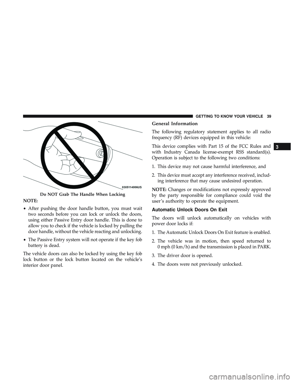
Do NOT Grab The Handle When Locking
3
GETTING TO KNOW YOUR VEHICLE 39
Page 95 of 486
Electrical Power Outlets
Your vehicle is equipped with 12 Volt (13 Amp) power
outlets that can be used to power cellular phones, small
electronics and other low powered electrical accessories.
The power outlets are labeled with either a “key” or a
“battery” symbol to indicate how the outlet is powered.
Power outlets labeled with a “key” can be powered when
the ignition is in the ON or ACC position, while the outlets
labeled with a “battery” are connected directly to the
battery and powered at all times.These power outlets can also operate a conventional cigar
lighter unit.
NOTE:
•
The front integrated center stack power outlet can be
changed from switched “ignition” to constant “battery”
powered all the time by moving the integrated center
stack fuse #12 in the Rear Power Distribution Center
from fuse location “IGN” to “B+.” Refer to “Fuses” in
“In Case Of Emergency.”
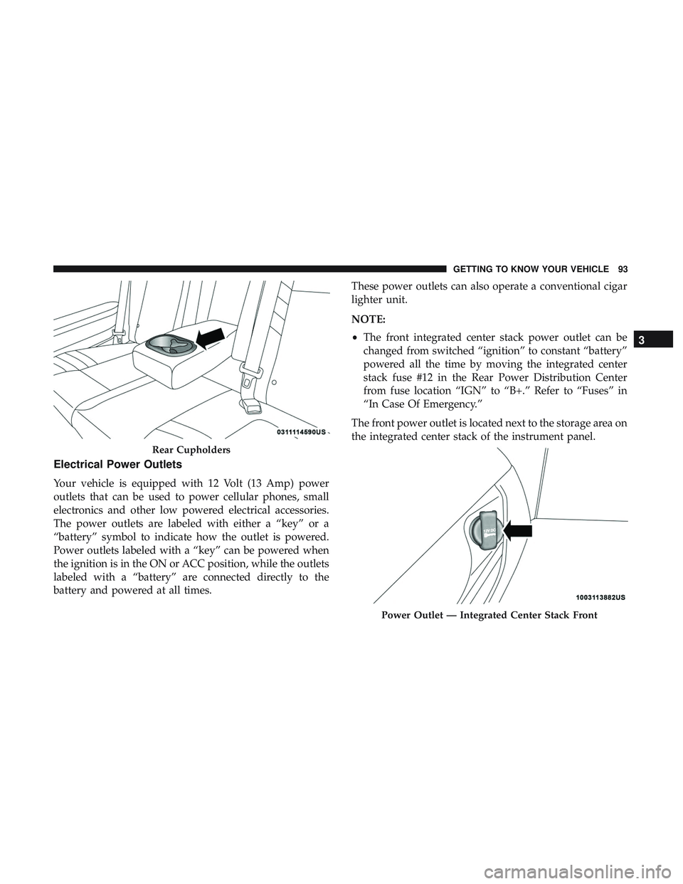
The front power outlet is located next to the storage area on
the integrated center stack of the instrument panel.
Rear Cupholders
Power Outlet — Integrated Center Stack Front
3
GETTING TO KNOW YOUR VEHICLE 93
Page 180 of 486
•Turn on the interior lights, which remain on as long as
the battery has power or for 15 minutes from the
intervention of the Enhanced Accident Response Sys-
tem.
• Unlock the power door locks.
Your vehicle may also be designed to perform any of these
other functions in response to the Enhanced Accident
Response System:
• Turn off the Fuel Filter Heater, Turn off the HVAC
Blower Motor, Close the HVAC Circulation Door
• Cut off battery power to the:
• Engine
• Electric Motor (if equipped)
• Electric power steering
• Brake booster
• Electric park brake
• Automatic transmission gear selector
• Horn
• Front wiper
• Headlamp washer pump NOTE:
After an accident, remember to cycle the ignition to
the STOP (OFF/LOCK) position and remove the key from
the ignition switch to avoid draining the battery. Carefully
check the vehicle for fuel leaks in the engine compartment
and on the ground near the engine compartment and fuel
tank before resetting the system and starting the engine. If
there are no fuel leaks or damage to the vehicle electrical
devices (e.g. headlights) after an accident, reset the system
by following the procedure described below.
Enhanced Accident Response System Reset
Procedure
In order to reset the Enhanced Accident Response System
functions after an event, the ignition switch must be
changed from ignition START or ON/RUN to ignition OFF.
Carefully check the vehicle for fuel leaks in the engine
compartment and on the ground near the engine compart-
ment and fuel tank before resetting the system and starting
the engine.
178 SAFETY
Page 471 of 486
Assist, Hill Start.......................... .135
Audio Systems (Radio) ...................... .387
Auto Down Power Windows ...................76
Automatic Door Locks .....................39, 40
Automatic Headlights ........................59
Automatic High Beams .......................58
Automatic Temperature Control (ATC) ............72
Automatic Transmission ..................... .221
Adding Fluid .....................343, 382, 384
Fluid And Filter Change ...................343
Fluid Change .......................... .343
Fluid Level Check .....................342, 343
Fluid Type ...................... .342, 382, 384
Special Additives ........................ .343
Automatic Transmission Limp Home Mode .....39, 226
Autostick Operation ............................. .227
Axle Fluid ........................... .382, 384
Axle Lubrication ....................... .382, 384
Back-Up ................................ .265
Battery ...............................114,322
Charging System Light .....................114
Keyless Key Fob Replacement ................21
Location .............................. .322Belts, Seat
............................... .201
Blind Spot Monitoring ...................... .138
Body Mechanism Lubrication ..................331
B-Pillar Location .......................... .350
Brake Assist System ........................ .129
Brake Control System ....................... .129
Brake Fluid ....................... .340, 382, 384
Brake System ......................... .340, 374
Fluid Check ..................... .340, 382, 384
Master Cylinder ........................ .340
Parking .............................. .213
Warning Light .......................112,374
Brake/Transmission Interlock ..................221
Brightness, Interior Lights .....................
63
Bulb Replacement ......................... .280
Bulbs, Light .......................... .203, 280
Camera, Rear ............................ .265
Capacities, Fluid .......................... .381
Caps, Filler Fuel ................................. .267
Oil (Engine) ........................ .320, 325
Power Steering ......................... .236
Radiator (Coolant Pressure) .................338
Carbon Monoxide Warning ................200, 380
12
INDEX 469
Page 476 of 486
Ignition..................................24
Switch .................................24
Information Center, Vehicle ...................101
Inside Rearview Mirror ....................54, 274
Instrument Cluster Descriptions ......................... .98, 121
Display .............................. .104
Instrument Panel Lens Cleaning ................371
Interior Appearance Care .....................370
Interior Lights ..............................62
Intermittent Wipers (Delay Wipers) ...............65
Introduction ................................4
iPod/USB/MP3 Control ..................... .442
Bluetooth Streaming Audio .................442
Jack Operation ........................... .344
Jump Starting ......................... .303, 304
Key Fob Arm The System ..........................32
Panic Alarm .............................20
Programming Additional Key Fobs ..........23, 31
Unlatch The Trunk ........................20
Key Fob Battery Service (Remote Keyless Entry) .....21
Key Fob Programming (Remote Keyless Entry) ......23Key-In Reminder
............................26
Keyless Enter-N-Go ..........................35
Enter The Trunk ..........................20
Keys ....................................17
Replacement ......................... .23, 31
Lane Change And Turn Signals .................61
Lane Change Assist ..........................61
Lap/Shoulder Belts ........................ .158
Latches ................................. .203
Hood ..................................80
Lead Free Gasoline ........................ .376
Leaks, Fluid ............................. .203
Life Of Tires ............................. .358
Light Bulbs .......................... .203, 280
Lights .................................. .203
AirBag .........................112, 167, 201
Automatic Headlights ......................59
Brake Assist Warning ..................... .134
Brake Warning .......................112,374
Bulb
Replacement ....................... .280
Courtesy/Reading .........................62
Cruise ............................... .121
Daytime Running .........................58
Dimmer Switch, Headlight ...................58
474 INDEX