steering wheel DODGE CHARGER 2013 7.G Owner's Guide
[x] Cancel search | Manufacturer: DODGE, Model Year: 2013, Model line: CHARGER, Model: DODGE CHARGER 2013 7.GPages: 631, PDF Size: 4.58 MB
Page 414 of 631
tapping one of the steering wheel-mounted shift paddles
(-/+) (if equipped), will manually select the transmission
gear, and will display that gear in the instrument cluster
as 5, 4, 3, 2, 1.Gear Ranges
DO NOT race the engine when shifting from PARK or
NEUTRAL into another gear range.
NOTE:
•After selecting any gear range, wait a moment to allow
the selected gear to engage before accelerating. This is
especially important when the engine is cold.
• If there is a need to restart the engine, be sure to cycle
the ignition to the OFF position before restarting.
Transmission gear engagement may be delayed after
restarting the engine if the key is not cycled to the OFF
position first.
Shift Lever
412 STARTING AND OPERATING
Page 420 of 631
NOTE:Even if the transmission can be reset, we recom-
mend that you visit your authorized dealer at your
earliest possible convenience. Your authorized dealer has
diagnostic equipment to determine if the problem could
recur.
If the transmission cannot be reset, authorized dealer
service is required.
Overdrive Operation
The automatic transmission includes an electronically
controlled Overdrive (fifth gear). The transmission will
automatically shift into Overdrive if the following con-
ditions are present:
• the shift lever is in the DRIVE position,
• vehicle speed is sufficiently high, and
• the driver is not heavily pressing the accelerator.
AUTOSTICK®
AutoStick® is a driver-interactive transmission feature
providing manual shift control, giving you more control
of the vehicle. AutoStick® allows you to maximize en-
gine braking, eliminate undesirable upshifts and down-
shifts, and improve overall vehicle performance.
This system can also provide you with more control during
passing, city driving, cold slippery conditions, mountain
driving, trailer towing, and many other situations.
Operation – Eight-Speed Transmission – If
Equipped
When the transmission is in DRIVE or SPORT mode, it
will operate automatically, shifting between the eight
available gears. To engage AutoStick®, simply tap one of
the steering wheel-mounted shift paddles (+/-) while in
DRIVE or SPORT mode. Tapping (-) to enter AutoStick®
418 STARTING AND OPERATING
Page 422 of 631
WARNING!
Do not downshift for additional engine braking on a
slippery surface. The drive wheels could lose their
grip and the vehicle could skid, causing a collision or
personal injury.
Operation – Five-Speed Transmission
When the shift lever is in the DRIVE position, the
transmission will operate automatically, shifting between
the five available gears. To engage AutoStick®, simply
tap the shift lever to the right or left (+/-) while in the
DRIVE position, or tap one of the steering wheel-
mounted shift paddles (+/-), if equipped. Tapping (-) to
enter AutoStick® mode will downshift the transmission
to the next lower gear, while using (+) to enter
AutoStick® mode will retain the current gear. When
AutoStick® is active, the current transmission gear is
displayed in the instrument cluster. In AutoStick® mode,the transmission will shift up or down when (+/-) is
manually selected by the driver (using the shift lever, or
the shift paddles [if equipped]), unless an engine lugging
or overspeed condition would result. It will remain in the
selected gear until another upshift or downshift is cho-
sen, except as described below.
•
If AutoStick® is engaged while in DRIVE mode, the
transmission will automatically shift up when maxi-
mum engine speed is reached. If the accelerator is fully
depressed, the transmission will downshift when pos-
sible (based on vehicle speed and gear).
• If AutoStick® is engaged while in SPORT mode,
manual gear selection will be maintained until either
SPORT mode is exited or as described below. The
transmission will not upshift automatically at redline
in this mode, nor will downshifts be obtained if the
accelerator pedal is pressed to the floor.
420 STARTING AND OPERATING
Page 435 of 631
WARNING!(Continued)
•The ABS cannot prevent the natural laws of phys-
ics from acting on the vehicle, nor can it increase
braking or steering efficiency beyond that afforded
by the condition of the vehicle brakes and tires or
the traction afforded.
• The ABS cannot prevent collisions, including those
resulting from excessive speed in turns, following
another vehicle too closely, or hydroplaning.
• The capabilities of an ABS equipped vehicle must
never be exploited in a reckless or dangerous
manner that could jeopardize the user’s safety or
the safety of others.
All vehicle wheels and tires must be the same size and
type and tires must be properly inflated to produce
accurate signals for the computer.
ELECTRONIC BRAKE CONTROL SYSTEM
Your vehicle is equipped with an advanced electronic
brake control system that include Anti-Lock Brake System
(ABS), Traction Control System (TCS), Brake Assist System
(BAS), and the Electronic Stability Control (ESC). All four
of these systems work together to enhance vehicle stability
and control in various driving conditions.
Also, your vehicle may be equipped with Hill Start Assist
(HSA), Ready Alert Braking, and Rain Brake Support.
Anti-Lock Brake System (ABS)
This system aids the driver in maintaining vehicle control
under adverse braking conditions by controlling hydrau-
lic brake pressure. This prevents wheel lock-up to help
avoid skidding on slippery surfaces during braking.
Refer to “Anti-Lock Brake System” in “Starting and
Operating” for further information.
5
STARTING AND OPERATING 433
Page 437 of 631
WARNING!
The BAS cannot prevent the natural laws of physics
from acting on the vehicle, nor can it increase the
traction afforded by prevailing road conditions. The
BAS cannot prevent collisions, including those result-
ing from excessive speed in turns, driving on very
slippery surfaces, or hydroplaning. The capabilities of
a BAS-equipped vehicle must never be exploited in a
reckless or dangerous manner that could jeopardize
the user’s safety or the safety of others.
Electronic Stability Control (ESC)
This system enhances directional control and stability of
the vehicle under various driving conditions. The ESC
corrects for oversteering and understeering the vehicleby applying the brake of the appropriate wheel. Engine
power may also be reduced to assist in counteracting the
condition of oversteer or understeer and help the vehicle
maintain the desired path.
The ESC uses sensors in the vehicle to determine the path
that the driver intends to steer the vehicle and compares
it to the actual path of the vehicle. When the actual path
does not match the intended path, the ESC applies the
brake of the appropriate wheel to assist in counteracting
the condition of oversteer or understeer.
•
Oversteer - when the vehicle is turning more than
appropriate for the steering wheel position.
• Understeer - when the vehicle is turning less than
appropriate for the steering wheel position.
5
STARTING AND OPERATING 435
Page 443 of 631
Synchronizing ESC
If the power supply is interrupted (battery dis-
connected or discharged), the “ESC Activation/
Malfunction Indicator Light” may illuminate
with the engine running. If this should occur,
turn the steering wheel completely to the left and then to
the right. The “ESC Activation/Malfunction Indicator
Light” should go out. However, if the light remains on,
have the ESC and BAS checked at your authorized dealer
as soon as possible.
TIRE SAFETY INFORMATION
Tire Markings
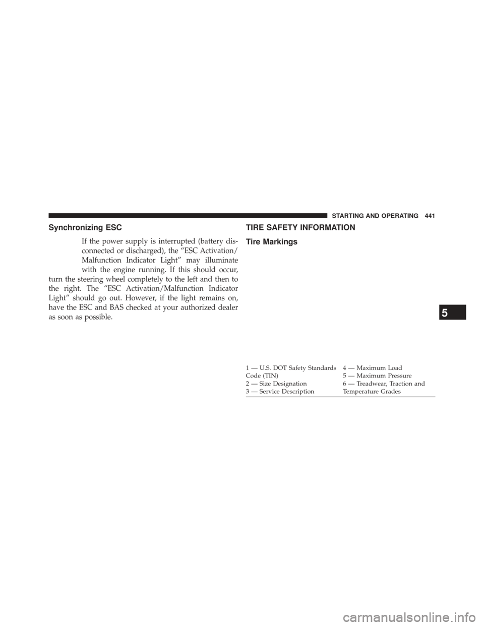
1 — U.S. DOT Safety Standards
Code (TIN) 4 — Maximum Load
2 — Size Designation 5 — Maximum Pressure
3 — Service Description 6 — Treadwear, Traction and
Temperature Grades
5
STARTING AND OPERATING 441
Page 464 of 631
when replacement is needed. Refer to the paragraph on
“Tread Wear Indicators”. Refer to the “Tire and Loading
Information” placard for the size designation of your tire.
The Load Index and Speed Symbol for your tire will be
found on the original equipment tire sidewall. See the
Tire Sizing Chart example found in the Tire Safety
Information section of this manual for more information
relating to the Load Index and Speed Symbol of a tire.
It is recommended to replace the two front tires or two
rear tires as a pair. Replacing just one tire can seriously
affect your vehicle’s handling. If you ever replace a
wheel, make sure that the wheel’s specifications match
those of the original wheels.
It is recommended you contact your authorized tire or
original equipment vehicle dealer with any questions
you may have on tire specifications or capability. Failure
to use equivalent replacement tires may adversely affect
the safety, handling, and ride of your vehicle.WARNING!
•Do not use a tire, wheel size or rating other than
that specified for your vehicle. Some combinations
of unapproved tires and wheels may change sus-
pension dimensions and performance characteris-
tics, resulting in changes to steering, handling, and
braking of your vehicle. This can cause unpredict-
able handling and stress to steering and suspen-
sion components. You could lose control and have
a collision resulting in serious injury or death. Use
only the tire and wheel sizes with load ratings
approved for your vehicle.
• Never use a tire with a smaller load index or
capacity, other than what was originally equipped
on your vehicle. Using a tire with a smaller load
index could result in tire overloading and failure.
You could lose control and have a collision.
(Continued)
462 STARTING AND OPERATING
Page 524 of 631
8. Disconnect the opposite end of the positive(+)jumper
cable from the positive (+)post of the booster battery.
9. Disconnect the positive (+)end of the jumper cable
from the remote positive (+)post of the discharged
vehicle.
If frequent jump-starting is required to start your vehicle
you should have the battery and charging system in-
spected at your authorized dealer.
CAUTION!
Accessories plugged into the vehicle power outlets
draw power from the vehicle’s battery, even when not
in use (i.e., cellular phones, etc.). Eventually, if plugged
in long enough without engine operation, the vehicle’s
battery will discharge sufficiently to degrade battery
life and/or prevent the engine from starting.
FREEING A STUCK VEHICLE
If your vehicle becomes stuck in mud, sand, or snow, it
can often be moved using a rocking motion. Turn the
steering wheel right and left to clear the area around the
front wheels. Then shift back and forth between DRIVE
and REVERSE while gently pressing the accelerator. Use
the least amount of accelerator pedal pressure that will
maintain the rocking motion, without spinning the
wheels or racing the engine.
CAUTION!
Racing the engine or spinning the wheels may lead to
transmission overheating and failure. Allow the en-
gine to idle with the transmission in NEUTRAL for at
least one minute after every five rocking-motion
cycles. This will minimize overheating and reduce
the risk of transmission failure during prolonged
efforts to free a stuck vehicle.
522 WHAT TO DO IN EMERGENCIES
Page 573 of 631
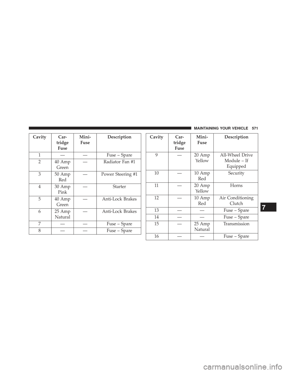
Cavity Car-tridgeFuse Mini-
Fuse Description
1 — — Fuse – Spare
2 40 Amp Green — Radiator Fan #1
3 50 Amp Red — Power Steering #1
4 30 Amp Pink — Starter
5 40 Amp Green — Anti-Lock Brakes
6 25 Amp Natural — Anti-Lock Brakes
7 — — Fuse – Spare
8 — — Fuse – SpareCavity Car- tridgeFuse Mini-
Fuse Description
9 — 20 Amp YellowAll-Wheel Drive
Module – IfEquipped
10 — 10 Amp RedSecurity
11 — 20 Amp YellowHorns
12 — 10 Amp RedAir Conditioning
Clutch
13 — — Fuse – Spare
14 — — Fuse – Spare
15 — 25 Amp NaturalTransmission
16 — — Fuse – Spare
7
MAINTAINING YOUR VEHICLE 571
Page 579 of 631
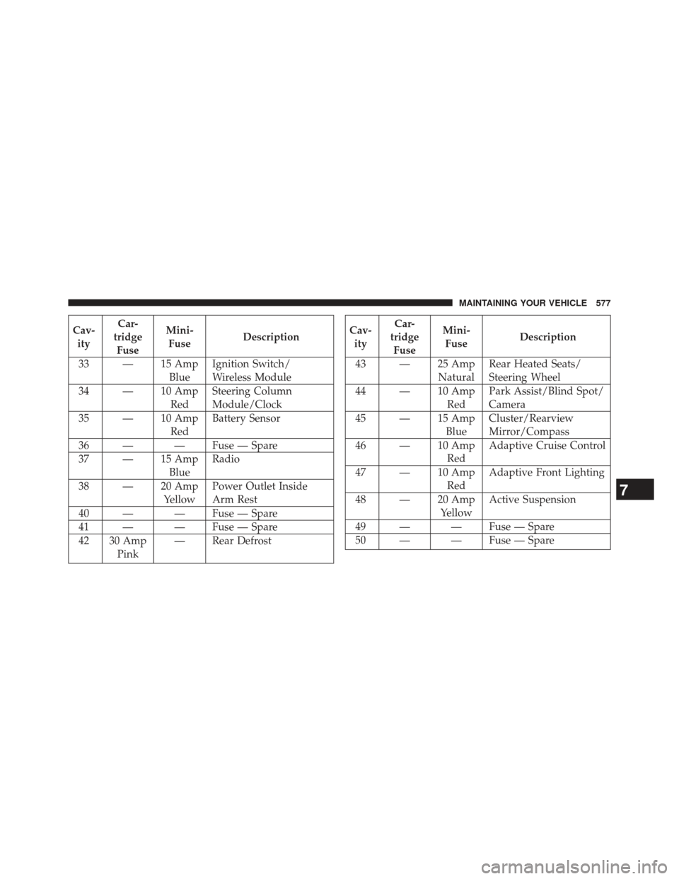
Cav-ity Car-
tridge Fuse Mini-
Fuse Description
33 — 15 Amp BlueIgnition Switch/
Wireless Module
34 — 10 Amp RedSteering Column
Module/Clock
35 — 10 Amp RedBattery Sensor
36 — — Fuse — Spare
37 — 15 Amp BlueRadio
38 — 20 Amp YellowPower Outlet Inside
Arm Rest
40 — — Fuse — Spare
41 — — Fuse — Spare
42 30 Amp Pink — Rear DefrostCav-
ity Car-
tridge Fuse Mini-
Fuse Description
43 — 25 Amp NaturalRear Heated Seats/
Steering Wheel
44 — 10 Amp RedPark Assist/Blind Spot/
Camera
45 — 15 Amp BlueCluster/Rearview
Mirror/Compass
46 — 10 Amp RedAdaptive Cruise Control
47 — 10 Amp RedAdaptive Front Lighting
48 — 20 Amp YellowActive Suspension
49 — — Fuse — Spare
50 — — Fuse — Spare
7
MAINTAINING YOUR VEHICLE 577