lock DODGE CHARGER 2014 7.G Owner's Guide
[x] Cancel search | Manufacturer: DODGE, Model Year: 2014, Model line: CHARGER, Model: DODGE CHARGER 2014 7.GPages: 148, PDF Size: 3.77 MB
Page 95 of 148
Road Tire Installation
1. Mount the road tire on the axle.
2. Install the remaining lug nuts with the cone shaped end of the nut toward the wheel.Lightly tighten the lug nuts.
3. Lower the vehicle to the ground by turning the jack handle counterclockwise.
4. Finish tightening the lug nuts. Push down on the wrench while at the end of the handle for increased leverage. Tighten the lug nuts in a star pattern until each nut has been
tightened twice. The correct tightness of each lug nut is 130 ft-lbs (176 N·m). If in doubt
about the correct tightness, have them checked with a torque wrench by your authorized
dealer or service station.
5. After 25 miles (40 km) check the lug nut torque with a torque wrench to ensure that all lug nuts are properly seated against the wheel.
CAUTION!
Do not attempt to raise the vehicle by jacking on locations other than those indicated in
the Jacking Instructions for this vehicle.
WHAT TO DO IN EMERGENCIES
93
Page 96 of 148
WARNING!
• Do not attempt to change a tire on the side of the vehicle close to moving traffic. Pullfar enough off the road to avoid the danger of being hit when operating the jack or
changing the wheel.
• Being under a jacked-up vehicle is dangerous. The vehicle could slip off the jack and
fall on you. You could be crushed. Never put any part of your body under a vehicle that
is on a jack.
• Never start or run the engine while the vehicle is on a jack. If you need to get under a
raised vehicle, take it to a service center where it can be raised on a lift.
• The jack is designed to be used as a tool for changing tires only. The jack should not
be used to lift the vehicle for service purposes. The vehicle should be jacked on a firm
level surface only. Avoid ice or slippery areas.
• A loose tire or jack thrown forward in a collision or hard stop could endanger the
occupants of the vehicle. Always stow the jack parts and the spare tire in the places
provided.
• Carefully follow these tire changing warnings to help prevent personal injury or
damage to your vehicle:
• Always park on a firm, level surface as far from the edge of the roadway as possible
before raising the vehicle.
• Turn on the Hazard Warning flasher.
• Block the wheel diagonally opposite the wheel to be raised.
• Set the parking brake firmly and set an automatic transmission in PARK; a manual
transmission in REVERSE.
• Do not let anyone sit in the vehicle when it is on a jack.
• Do not get under the vehicle when it is on a jack.
• Only use the jack in the positions indicated and for lifting this vehicle during a tire
change.
• If working on or near a roadway, be extremely careful of motor traffic.
• Raising the vehicle higher than necessary can make the vehicle less stable. It could
slip off the jack and hurt someone near it. Raise the vehicle only enough to remove
the tire.
• To avoid the risk of forcing the vehicle off the jack, do not fully tighten the wheel nuts
until the vehicle has been lowered. Failure to follow this warning may result in
personal injury.
• A loose tire or jack thrown forward in a collision or hard stop could endanger the
occupants of the vehicle. Always stow the jack parts and the spare tire in the places
provided.
• The limited-use spare tires are for emergency use only. Installation of this limited-
use spare tire affects vehicle handling. With this tire, do not drive more than 60 mph
(100 km/h). Keep inflated to the cold tire inflation pressure listed on either your tire
placard or limited-use spare tire and wheel assembly. Replace (or repair) the original
tire at the first opportunity and reinstall it on your vehicle. Failure to do so could result
in loss of vehicle control.
WHAT TO DO IN EMERGENCIES
94
Page 101 of 148
(F) Sealant Bottle And Hose Replacement:
1. Uncoil the Sealant Hose (6) (clear in color).
2. Locate the round Sealant Bottle release button in the recessed area under the sealantbottle.
3. Press the Sealant Bottle release button. The Sealant Bottle (1) will pop up. Remove the bottle and dispose of it accordingly.
4. Clean any remaining sealant from the TIREFIT housing.
5. Position the new Sealant Bottle (1) in the housing so that the Sealant Hose (6) aligns with the hose slot in the front of the housing. Press the bottle into the housing. An audible
click will be heard indicating the bottle is locked into place.
6. Verify that the cap is installed on the fitting at the end of the Sealant Hose (6) and return the hose to its storage area (located on the bottom of the air pump).
7. Return the TIREFIT kit to its storage location in the vehicle.
CAUTION!
• The metal end fitting from Power Plug (8) may get hot after use, so it should be handled carefully.
• Failure to reinstall the cap on the fitting at the end of the Sealant Hose (6) can result
in sealant contacting your skin, clothing, and the vehicle’s interior. It can also result in
sealant contacting internal TIREFIT kit components which may cause permanent
damage to the kit.
WHAT TO DO IN EMERGENCIES
99
Page 107 of 148
4. Insert the screwdriver into the slot in the center of the lever, and disengage the leverlocking tab by pushing it to the right.
5. While holding the locking tab in the disengaged position, pull the tether
strap to rotate the lever up and rear-
ward, until it locks in place in the ver-
tical position. The vehicle is now out
of PARK and can be towed. Release
the parking brake only when the ve-
hicle is securely connected to a tow
vehicle.
To Reset The Manual Park Release:
1. Push the latch (at the base of the lever, on the rear side) rearward (away from the lever) to unlatch the lever.
2. Rotate the Manual Park Release lever forward and down, to its original position, until the locking tab snaps into place to secure the lever.
3. Pull up gently on the tether strap to confirm that the lever is locked in its stowed position.
4. Tuck the tether strap into the base of the console. Reinstall the console storage bin.
WHAT TO DO IN EMERGENCIES
105
Page 111 of 148
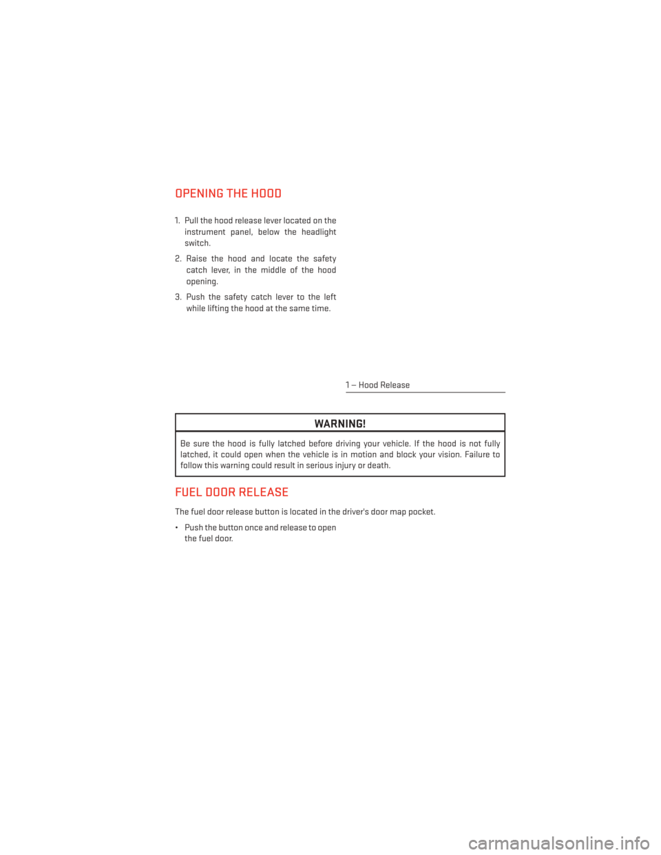
OPENING THE HOOD
1. Pull the hood release lever located on theinstrument panel, below the headlight
switch.
2. Raise the hood and locate the safety catch lever, in the middle of the hood
opening.
3. Push the safety catch lever to the left while lifting the hood at the same time.
WARNING!
Be sure the hood is fully latched before driving your vehicle. If the hood is not fully
latched, it could open when the vehicle is in motion and block your vision. Failure to
follow this warning could result in serious injury or death.
FUEL DOOR RELEASE
The fuel door release button is located in the driver's door map pocket.
• Push the button once and release to openthe fuel door.
1 — Hood Release
MAINTAINING YOUR VEHICLE
109
Page 127 of 148
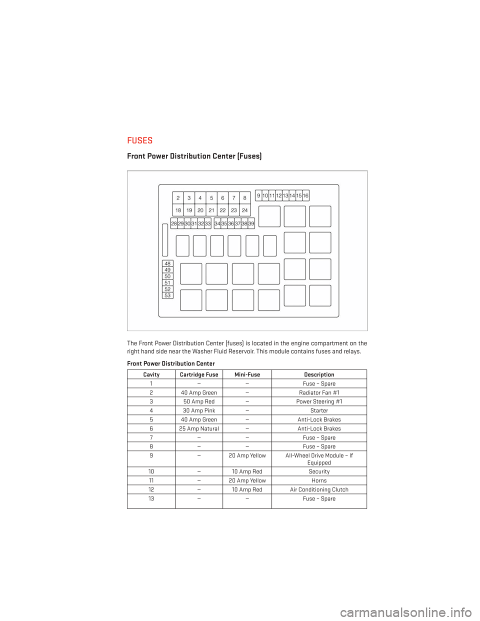
FUSES
Front Power Distribution Center (Fuses)
The Front Power Distribution Center (fuses) is located in the engine compartment on the
right hand side near the Washer Fluid Reservoir. This module contains fuses and relays.
Front Power Distribution Center
Cavity Cartridge Fuse Mini-FuseDescription
1 — — Fuse – Spare
2 40 Amp Green — Radiator Fan #1
3 50 Amp Red — Power Steering #1
4 30 Amp Pink — Starter
5 40 Amp Green — Anti-Lock Brakes
6 25 Amp Natural — Anti-Lock Brakes
7 — — Fuse – Spare
8 — — Fuse – Spare
9 — 20 Amp Yellow All-Wheel Drive Module – If
Equipped
10 — 10 Amp Red Security
11 — 20 Amp Yellow Horns
12 — 10 Amp Red Air Conditioning Clutch
13 —— Fuse – Spare
MAINTAINING YOUR VEHICLE
125
Page 128 of 148
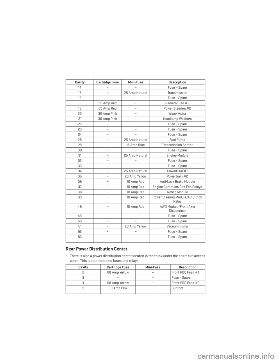
Cavity Cartridge Fuse Mini-FuseDescription
14 —— Fuse – Spare
15 — 25 Amp Natural Transmission
16 —— Fuse – Spare
18 50 Amp Red — Radiator Fan #2
19 50 Amp Red — Power Steering #2
20 30 Amp Pink — Wiper Motor
21 30 Amp Pink — Headlamp Washers
22 —— Fuse – Spare
23 —— Fuse – Spare
24 —— Fuse – Spare
28 — 25 Amp Natural Fuel Pump
29 — 15 Amp Blue Transmission Shifter
30 —— Fuse – Spare
31 — 25 Amp Natural Engine Module
32 —— Fuse – Spare
33 —— Fuse – Spare
34 — 25 Amp Natural Powertrain #1
35 — 20 Amp Yellow Powertrain #2
36 — 10 Amp Red Anti-Lock Brake Module
37 — 10 Amp Red Engine Controller/Rad Fan Relays
38 — 10 Amp Red Airbag Module
39 — 10 Amp Red Power Steering Module/AC Clutch
Relay
48 — 10 Amp Red AWD Module/Front Axle
Disconnect
49 —— Fuse – Spare
50 —— Fuse – Spare
51 — 20 Amp Yellow Vacuum Pump
52 —— Fuse – Spare
53 —— Fuse – Spare
Rear Power Distribution Center
• There is also a power distribution center located in the trunk under the spare tire access
panel. This center contains fuses and relays.
Cavity Cartridge Fuse Mini-Fuse Description
2 60 Amp Yellow — Front PDC Feed #1
3 — — Fuse – Spare
4 60 Amp Yellow — Front PDC Feed #2
5 30 Amp Pink — Sunroof
MAINTAINING YOUR VEHICLE
126
Page 129 of 148
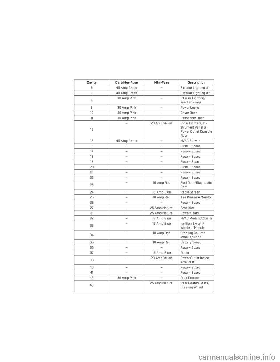
CavityCartridge Fuse Mini-Fuse Description
6 40 Amp Green — Exterior Lighting #1
7 40 Amp Green — Exterior Lighting #2
8 30 Amp Pink
— Interior Lighting/
Washer Pump
9 30 Amp Pink — Power Locks
10 30 Amp Pink — Driver Door
11 30 Amp Pink — Passenger Door
12 —
20 Amp Yellow Cigar Lighters, In-
strument Panel &
Power Outlet Console
Rear
15 40 Amp Green — HVAC Blower
16 —— Fuse — Spare
17 —— Fuse — Spare
18 —— Fuse — Spare
19 —— Fuse — Spare
20 —— Fuse — Spare
21 —— Fuse — Spare
22 —— Fuse — Spare
23 —
10 Amp Red Fuel Door/Diagnostic
Port
24 —15 Amp Blue Radio Screen
25 —10 Amp Red Tire Pressure Monitor
26 —— Fuse — Spare
27 —25 Amp Natural Amplifier
31 —25 Amp Natural Power Seats
32 —15 Amp Blue HVAC Module/Cluster
33 —
15 Amp Blue Ignition Switch/
Wireless Module
34 —
10 Amp Red Steering Column
Module/Clock
35 —10 Amp Red Battery Sensor
36 —— Fuse — Spare
37 —15 Amp Blue Radio
38 —
20 Amp Yellow Power Outlet Inside
Arm Rest
40 —— Fuse — Spare
41 —— Fuse — Spare
42 30 Amp Pink — Rear Defrost
43 —
25 Amp Natural Rear Heated Seats/
Steering Wheel
MAINTAINING YOUR VEHICLE
127
Page 137 of 148
FAQ’s
GETTING STARTED
• How do I install my LATCH Equipped Child Seat? pg. 18
• How do I program my Front Seat Memory? pg. 21
ELECTRONICS
• How do I know which radio I have?• Uconnect® 4.3, 4.3S pg. 47
• Uconnect® 8.4, 8.4N pg. 48
• How do I select the AUX music source? pg. 60
• How do I set the clock on my radio?
• Uconnect® 4.3, 4.3S pg. 47
• Uconnect® 8.4, 8.4N pg. 48
• How do I use the Navigation feature? pg. 56
• How do I pair my cell phone via Bluetooth® with the Uconnect® Hands-Free Voice Activation System? pg. 62
UTILITY
• How do I know how much I can tow with my Dodge Charger? pg. 77
WHAT TO DO IN EMERGENCIES
• What do I do if my TPMS warning light is blinking? pg. 84
• How do I change a flat tire? pg. 89
• How do I Jump-Start my vehicle? pg. 101
MAINTAINING YOUR VEHICLE
• Where is my Fuse Block located? pg. 125
• What type of oil do I use? pg. 114
• How often should I change my engine’s oil? pg. 116
• How often should I change my SRT engine’s oil? pg. 121
• What should my tire pressure be set at? pg. 130
FREQUENTLY ASKED QUESTIONS
135
Page 138 of 148
Adaptive Cruise Control (ACC) (CruiseControl)................34
AdjustablePedals.............27
Airbag ...................16
Airbag Light ................87
Alarm Vehicle Security Alarm ........14
Alarm (Security Alarm) ..........14
Anti-Lock Warning Light .........87
Arming System (Security Alarm) .....14
Assistance Towing ............84
Automatic Headlights ...........31
Automatic High Beams ..........31
Automatic Oil Change Indicator .....87
Automatic Temperature Control (ATC) . .40
Automatic Transmission Autostick ...............78
Fluid Type ..............114
Autostick .................78
AxleFluid.................114
BrakeFluid................114
Break-In Recommendations, New Vehicle .................29
Bulb Replacement ............131
Calibration, Compass ...........71
ChangingAFlatTire...........89
Charging System Light ..........86
Child Restraints CarSeat................17
Child Restraints ............17
Child Seat Installation .......18,19
Installing Child Restraints Using
The Vehicle Seat Belt .........19
Lower Anchors And Tethers For
Children ..........17, 18, 19, 20
Using The Top Tether Anchorage. .19, 20
ChildSeat.................18
Cluster Warning/Indicator Lights Anti-Lock Brake (ABS) Light .....87
Charging System Light ........86
Electronic Throttle Control (ETC)
Indicator Light ............87
Engine Temperature Warning Light .85
Oil Pressure Warning Light ......86
Tire Pressure Monitoring
System (TPMS) Light .........84 Compass Calibration
...........71
Cooling System Coolant Capacity ..........114
Cruise Control (Speed Control) ......32
Cruise Light ................32
Cupholders Heated/Cooled (Beverage Holder) . .25
Customer Assistance ..........132
Customer Programmable Features ....72
Deck Lid, Emergency Release .......14
Deck Lid, Power Release .........14
Defects, Reporting ............133
Dimmer Control ..............32
Dimmer Switch, Headlight ........32
Disabled Vehicle Towing .........84
Disarming, Security System .......15
DoorLocks.................8
ECO....................71
Electronics Your Vehicle's Sound System . .44, 45
Electronic Speed Control (Cruise Control) ............32
Electronic Stability Control (ESC) .....84
Electronic Stability Control (ESC) OFF Indicator ................86
Electronic Throttle Control Warning Light .............87
Electronic Vehicle Information Center (EVIC)................70,71
Emergency Deck Lid Release .......14
Emergency, In Case of Brake Warning Light .........86
Jacking ................89
Overheating .............88
Towing ................84
Emergency Key ...............9
Emergency Trunk Release ........14
Engine Break-In Recommendations .....29
Compartment............ .111
Oil Change Interval ..........87
Oil Selection .............114
Overheating .............88
Starting ................12
Stopping ...............12
Temperature Warning Light .....85
INDEX
136