remote start DODGE CHARGER 2014 7.G User Guide
[x] Cancel search | Manufacturer: DODGE, Model Year: 2014, Model line: CHARGER, Model: DODGE CHARGER 2014 7.GPages: 148, PDF Size: 3.77 MB
Page 3 of 148
INTRODUCTION/WELCOME
WELCOME FROM CHRYSLER GROUP LLC . . . 2
CONTROLS AT A GLANCE
DRIVER COCKPIT................4
INSTRUMENT CLUSTER .............6
GETTING STARTED
KEYFOB .....................8
REMOTE START................10
KEYLESS ENTER-N-GO™ ...........10
TRUNK LOCK AND RELEASE .........14
VEHICLE SECURITY ALARM ..........14
SEATBELT ...................15
SUPPLEMENTAL RESTRAINT SYSTEM (SRS) —
AIRBAGS ....................16
CHILD RESTRAINTS ..............17
FRONT SEATS .................21
REARSEATS ..................23
HEATED/VENTILATED SEATS .........24
HEATED AND COOLED CUPHOLDERS ....25
HEATED STEERING WHEEL ..........26
ADJUSTABLE PEDALS .............27
TILT/TELESCOPING STEERING COLUMN . . . 28
OPERATING YOUR VEHICLE
ENGINE BREAK-IN RECOMMENDATIONS . . . 29
TURN SIGNAL/WIPER/WASHER/HIGH BEAM
LEVER ......................30
HEADLIGHT SWITCH ..............31
SPEED CONTROL ...............32
ELECTRONIC SHIFTER — 3.6L ENGINE ....37
TRANSMISSION MODES/AUTOSTICK® ....38
CLIMATE CONTROLS .............40
POWER SUNROOF ...............42
WIND BUFFETING ...............43
ELECTRONICS
YOUR VEHICLE'S SOUND SYSTEM ......44
IDENTIFYING YOUR RADIO ...........46
Uconnect® 4.3 & 4.3S AT A GLANCE .....47
Uconnect® 8.4 & 8.4N AT A GLANCE .....48
RADIO ......................50
SiriusXM SATELLITE RADIO ..........51
iPod®/CD/AUX CONTROLS ..........54
GARMIN® NAVIGATION .............56
SiriusXM TRAVEL LINK .............59
STEERING WHEEL AUDIO CONTROLS ....60
PLAYING iPod®/USB/MP3 DEVICES .....60
Uconnect® PHONE ...............62
Uconnect® VOICE COMMAND .........68
ELECTRONIC VEHICLE INFORMATION
CENTER (EVIC) .................70
PROGRAMMABLE FEATURES .........71
UNIVERSAL GARAGE DOOR OPENER .....73
POWER OUTLET ................75
UTILITY
TRAILER TOWING WEIGHTS (MAXIMUM
TRAILERWEIGHTRATINGS) ..........77
RECREATIONAL TOWING (BEHIND
MOTORHOME, ETC.) ..............77
SRT
AUTOSTICK®..................78ELECTRONIC CONTROL DAMPING SYSTEM . . . 79SRT PERFORMANCE FEATURES .......80
SUMMER/THREE-SEASON TIRES .......83
WHAT TO DO IN EMERGENCIES
ROADSIDE ASSISTANCE............84INSTRUMENT CLUSTER WARNING LIGHTS..84
IF YOUR ENGINE OVERHEATS .........88
JACKING AND TIRE CHANGING ........89
TIREFIT KIT ...................95
BATTERY LOCATION ..............101
JUMP-STARTING ...............101
SHIFT LEVER OVERRIDE — 5 SPEED
TRANSMISSION ................103
TOWING A DISABLED VEHICLE .......106
FREEING A STUCK VEHICLE .........107
EVENT DATA RECORDER (EDR) ........108
MAINTAINING YOUR VEHICLE
OPENING THE HOOD.............109
FUEL DOOR RELEASE ............109
ENGINE COMPARTMENT ...........111
FLUIDS AND CAPACITIES ...........114
MAINTENANCE SCHEDULE ..........116
SRT MAINTENANCE SCHEDULE .......121
FUSES .....................125
TIRE PRESSURES ...............130
WHEEL AND WHEEL TRIM CARE .......131
EXTERIOR BULBS ...............131
CONSUMER ASSISTANCE
CHRYSLER GROUP LLC CUSTOMER
CENTER....................132
CHRYSLER CANADA INC. CUSTOMER
CENTER ....................132
ASSISTANCE FOR THE HEARING
IMPAIRED ...................132
PUBLICATIONS ORDERING ..........132
REPORTING SAFETY DEFECTS IN
THEUNITEDSTATES .............133
MOPAR® ACCESSORIES
AUTHENTIC ACCESSORIES BY MOPAR® . . 134
FREQUENTLY ASKED QUESTIONS
FAQ’s .....................135
INDEX....................136
TABLE OF CONTENTS
Page 5 of 148
VEHICLES SOLD IN CANADA
With respect to any vehicles sold in Canada, the name Chrysler Group LLC shall be deemed
to be deleted and the name Chrysler Canada Inc. used in substitution.
WARNING!
• Pedals that cannot move freely can cause loss of vehicle control and increase therisk of serious personal injury.
• Always make sure that objects cannot fall into the driver foot well while the vehicle is
moving. Objects can become trapped under the brake pedal and accelerator pedal
causing a loss of vehicle control.
• Failure to properly follow floor mat installation or mounting can cause interference
with the brake pedal and accelerator pedal operation causing loss of control of the
vehicle.
• Never leave children alone in a vehicle, or with access to an unlocked vehicle.
Allowing children to be in a vehicle unattended is dangerous for a number of reasons.
A child or others could be seriously or fatally injured. Children should be warned not
to touch the parking brake, brake pedal or the shift lever/gear selector.
• Never use the ‘PARK’ position as a substitute for the parking brake. Always apply the parking brake fully when parked to guard against vehicle movement and possible
injury or damage.
• Refer to your Owner's Manual on the DVD for further details.
USE OF AFTERMARKET PRODUCTS (ELECTRONICS)
The use of aftermarket devices including cell phones, MP3 players, GPS systems, or
chargers may affect the performance of on-board wireless features including Keyless
Enter-N-Go™ and Remote Start range. If you are experiencing difficulties with any of your
wireless features, try disconnecting your aftermarket devices to see if the situation im-
proves. If your symptoms persist, please see an authorized dealer.
CHRYSLER, DODGE, JEEP, RAM TRUCK, SRT, ATF+4, MOPAR and Uconnect are registered
trademarks of Chrysler Group LLC.
COPYRIGHT ©2014 CHRYSLER GROUP LLC
INTRODUCTION/WELCOME
3
Page 10 of 148
KEY FOB
Locking And Unlocking The Doors
• Push and release the LOCK button on theRKE transmitter to lock all doors. The turn
signal lights will flash and the horn will
chirp to acknowledge the signal.
• Push and release the UNLOCK button on the RKE transmitter once to unlock the
driver's door or twice within five seconds
to unlock all doors. The turn signal lights
will flash to acknowledge the unlock sig-
nal. The illuminated entry system will also
turn on.
1st Push Of Key Fob Unlocks
This feature lets you program the system to
unlock either the driver's door or all doors on
the first push of the UNLOCK button on the
RKE transmitter. To change the current set-
ting, refer to your Owner's Manual on the DVD
for further information.
Opening The Trunk
• Press the Trunk Release button on the transmitter two times within five seconds to open the trunk.
Panic Alarm
• Press the PANIC button once to turn the panic alarm on.
• Wait approximately three seconds and press the button a second time to turn the panicalarm off.
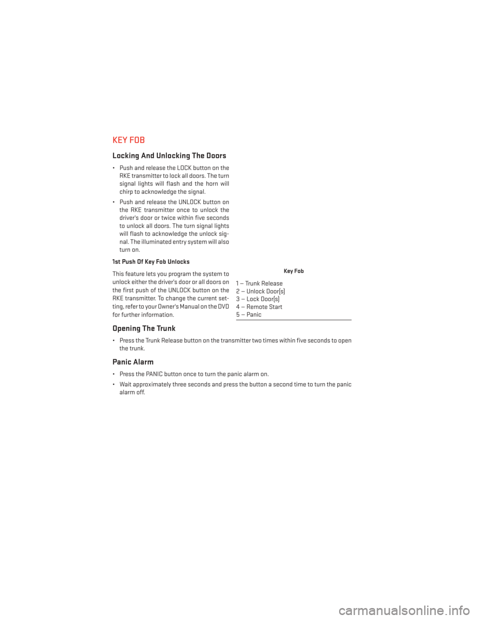
Key Fob
1 — Trunk Release
2 — Unlock Door(s)
3 — Lock Door(s)
4 — Remote Start
5 — Panic
GETTING STARTED
8
Page 12 of 148
REMOTE START
• Push the REMOTE START buttonx2on the Key Fob twice within five seconds. Pushing
the REMOTE START button a third time shuts the engine off.
• To drive the vehicle, push the UNLOCK button and cycle the ignition to the ON/RUN position.
With Remote Start, the engine will only run for 15 minutes (timeout) unless the ignition is
cycled to the ON/RUN position.
The vehicle must be cycled to the ON/RUN position after two consecutive timeouts.
WARNING!
• Do not start or run an engine in a closed garage or confined area. Exhaust gas contains Carbon Monoxide (CO) which is odorless and colorless. Carbon Monoxide is
poisonous and can cause you or others to be severely injured or killed when inhaled.
• Keep Key Fob transmitters away from children. Operation of the Remote Start
System, windows, door locks or other controls could cause you and others to be
severely injured or killed.
KEYLESS ENTER-N-GO™
The Keyless Enter-N-Go™ system is an enhancement to the vehicle's Key Fob. This feature
allows you to lock and unlock the vehicle's door(s) and trunk without having to press the Key Fob
lock or unlock buttons, as well as starting and stopping the vehicle with the press of a button.
To Unlock From The Driver Or Passenger Side:
• With a valid Keyless Enter-N-Go™ Key Foblocated outside the vehicle and within 5 ft
(1.5 m) of the driver or passenger side door
handle, lift either front door handle to un-
lock the door automatically.
To Lock The Vehicle
• Both front door handles have LOCK buttons located on the outside of the handle. Withone of the vehicle's Keyless Enter-N-Go™ Key Fobs located outside the vehicle and within
5 ft (1.5 m) of the driver's or passenger front door handle, press the door handle LOCK
button to lock all four doors and trunk.
GETTING STARTED
10
Page 16 of 148
TRUNK LOCK AND RELEASE
• The trunk lid can be released from inside the vehicle by pressing the TRUNK RELEASEbutton located on the instrument panel to the left of the steering wheel.
NOTE:
The transmission must be in PARK before the button will operate.
• The trunk lid can be released from outside the vehicle by pressing the TRUNK button on the Remote Keyless Entry (RKE) transmitter twice within five seconds.
• With the ignition in the ON/RUN position, the Trunk Open symbol will display in the instrument cluster indicating that the trunk is open. The odometer display will reappear
once the trunk is closed.
• With the ignition in the OFF position or the key removed from the ignition switch, the Trunk Open symbol will display until the trunk is closed.
• Refer to your Owner's Manual on the DVD for further information on trunk operation with the Passive Entry feature.
Trunk Emergency Release
• As a security measure, a Trunk Internal Emergency Release lever is built into the trunklatching mechanism. In the event of an individual being locked inside the trunk, the trunk
can be simply opened by pulling on the glow-in-the-dark handle attached to the trunk
latching mechanism.
WARNING!
Do not allow children to have access to the trunk, either by climbing into the trunk from
outside, or through the inside of the vehicle. Always close the trunk lid when your vehicle
is unattended. Once in the trunk, young children may not be able to escape, even if they
entered through the rear seat. If trapped in the trunk, children can die from suffocation or
heat stroke.
VEHICLE SECURITY ALARM
To Arm:
• Press the Keyless Enter-N-Go™ START/STOP button until the Electronic Vehicle Informa-tion Center (EVIC) indicates that the vehicle ignition is “OFF”. Press the power door lock
switch while the door is open, press the Key Fob LOCK button, or with one of the Key Fobs
located outside the vehicle and within 5 ft (1.5 m) of the driver's and passenger front door
handles, press the Keyless Enter-N-Go™ LOCK button located on the door handle.
NOTE:
After pressing the Keyless Enter-N-Go™ LOCK button, you must wait two seconds before
you can lock or unlock the vehicle via the door handle.
GETTING STARTED
14
Page 26 of 148
HEATED/VENTILATED SEATS
Front Ventilated Seats
Located in the seat cushion and seatback are small fans that draw the air from the
passenger compartment and pull air through fine perforations in the seat cover to help keep
the driver and front passenger cooler in higher ambient temperatures.
There are two ventilated seat control buttons located in the touchscreen that allow the
driver and passenger to operate the seats independently.
The ventilated seat buttons are used to control the speed of the fans located in the seat.
To operate the system, press the “Controls” button on touchscreen located on the bottom
of the Uconnect® display.
• Press the ventilated seat button
once to choose HIGH.
• Press the ventilated seat button
a second time to choose LOW.
• Press the ventilated seat button
a third time to turn the ventilated seat OFF.
NOTE:
Vehicle Equipped With Remote Start
On models that are equipped with remote start, this feature can be programmed to come on
during a remote start through the Uconnect® system. Refer to “Uconnect® Settings” in
“Understanding Your Instrument Panel” in the Owner's Manual on the DVD.
Front Heated Seats
• There are two heated seat control buttons located in the touchscreen that allow the driver and passenger to operate the seats independently.
• Press the heated seat button
once to turn the High setting On. Press the heated seat
button a second time to turn the Low setting On. Press the heated seat button a third time
to turn the heating elements Off.
• If the High-level setting is selected, the system will automatically switch to Low-level after approximately 60 minutes. The Low-level setting will turn Off automatically after
approximately 45 minutes.
NOTE:
Vehicle Equipped With Remote Start
On models that are equipped with remote start, this feature can be programmed to come on
during a remote start through the Uconnect® system. Refer to “Uconnect® Settings” in
“Understanding Your Instrument Panel” in the Owner's Manual on the DVD.
GETTING STARTED
24
Page 28 of 148
WARNING!
• Persons who are unable to feel pain to the skin because of advanced age, chronicillness, diabetes, spinal cord injury, medication, alcohol use, exhaustion or other
physical conditions must exercise care when using the heated cup holders. It may
cause burns even at low temperatures, especially if used for long periods of time.
• Keep the cup holders free of debris such as anything that insulates against heat, for this may cause the cup holders to overheat. Coming in contact with overheated cup
holders could cause serious burns due to the increased surface temperature.
HEATED STEERING WHEEL
The steering wheel contains a heating element that heats the steering wheel to one
temperature setting.
The heated steering wheel control button is located within the climate or controls screen of
the touchscreen.
• Press the heated steering wheel button
once to turn the heating element On.
•
Press the heated steering wheel buttona second time to turn the heating element Off.
Once the heated steering wheel has been turned on, it will operate for up to 80 minutes
before automatically shutting off. The heated steering wheel can shut off early or may not
turn on when the steering wheel is already warm.
NOTE:
Vehicle Equipped With Remote Start
On models that are equipped with remote start, this feature can be programmed to come on
during a remote start through the Uconnect® system. Refer to “Uconnect® Settings” in
“Understanding Your Instrument Panel” in the Owner's Manual on the DVD.
WARNING!
• Persons who are unable to feel pain to the skin because of advanced age, chronic illness, diabetes, spinal cord injury, medication, alcohol use, exhaustion, or other
physical conditions must exercise care when using the steering wheel heater. It may
cause burns even at low temperatures, especially if used for long periods.
• Do not place anything on the steering wheel that insulates against heat, such as a
blanket or steering wheel covers of any type and material. This may cause the
steering wheel heater to overheat.
GETTING STARTED
26
Page 74 of 148
Uconnect® 4.3 Customer Programmable Features
• The Uconnect® 4.3 system allows you to access Customer Programmable feature set-tings such as Display, Clock, Safety/Assistance, Lights, Doors & Locks, Heated Seats,
Engine Off Operation, Compass Settings, Audio, Phone/Bluetooth and SiriusXM Setup
through hard-keys and soft-keys.
• Press the Settings hard-key to on the right side of the unit to access the Settings screen, use the Page Up/Down soft-keys to scroll through the following settings. The following
feature settings are available:
• Display • Clock
• Safety / Assistance • Doors & Locks
• Heated Seats • Engine Off Options
• Compass Settings • Audio
• Phone / Bluetooth • SiriusXM Setup
• Auto-On Comfort & Remote Start • Lights
Uconnect® 8.4 Customer Programmable Features
• The Uconnect® 8.4 system allows you to access Customer Programmable feature set- tings such as Display, Clock, Safety/Assistance, Lights, Doors & Locks, Heated Seats,
Engine Off Operation, Compass Settings, Audio, Phone/Bluetooth and SiriusXM Setup
through soft-keys.
• Touch the More soft-key on the bottom of the screen, then touch the Settings soft-key to access the Settings screen. When making a selection, scroll up or down until the
preferred setting is highlighted, then press and release the preferred setting until a
check-mark appears next to the setting, showing that setting has been selected. The
following feature settings are available:
• Display • Clock
• Safety & Driving Assistance • Doors & Locks
• Auto-On Comfort & Remote Start • Engine Off Options
• Compass Settings • Audio
• Phone / Bluetooth • SiriusXM Setup
• Lights
ELECTRONICS
72
Page 103 of 148
BATTERY LOCATION
The battery is stored under an access cover in the trunk. Remote battery posts are located
on the right side of the engine compartment for jump-starting.
JUMP-STARTING
If your vehicle has a discharged battery it can be jump-started using a set of jumper cables
and a battery in another vehicle or by using a portable battery booster pack.
Jump-starting can be dangerous if done improperly so please follow the procedures in this
section carefully.
NOTE:
When using a portable battery booster pack
follow the manufacturer’s operating instruc-
tions and precautions.
Preparations For Jump-Start
The battery is stored under an access cover
in the trunk. Remote battery posts are lo-
cated on the right side of the engine com-
partment for jump-starting.
NOTE:
The remote battery posts are viewed by
standing on the right side of the vehicle
looking over the fender.
• Set the parking brake, shift the automatic transmission into PARK and turn the ignition toOFF.
• Turn off the heater, radio, and all unnecessary electrical accessories.
• If using another vehicle to jump-start the battery, park the vehicle within the jumper cables reach, set the parking brake and make sure the ignition is OFF.
WHAT TO DO IN EMERGENCIES
101
Page 104 of 148
Jump-Starting Procedure
1. Connect the positive(+)end of the jumper cable to the remote positive (+)post of the
discharged vehicle.
2. Connect the opposite end of the positive (+)jumper cable to the positive (+)post of the
booster battery.
3. Connect the negative end (-)of the jumper cable to the negative (-)post of the booster
battery.
4. Connect the opposite end of the negative (-)jumper cable to the remote negative (-)post
of the vehicle with the discharged battery.
5. Start the engine in the vehicle that has the booster battery, let the engine idle a few minutes, and then start the engine in the vehicle with the discharged battery.
Once the engine is started, remove the jumper cables in the reverse sequence:
1. Disconnect the negative (-)end of the jumper cable from the remote negative (-)post of
the vehicle with the discharged battery.
2. Disconnect the opposite end of the negative (-)jumper cable from the negative (-)post of
the booster battery.
3. Disconnect the positive (+)end of the jumper cable from the positive (+)post of the
booster battery.
4. Disconnect the opposite end of the positive (+)jumper cable from the remote positive (+)
post of the discharged vehicle.
NOTE:
If frequent jump-starting is required to start your vehicle you should have the battery and
charging system inspected at your authorized dealer.
CAUTION!
• Do not use a portable battery booster pack or any other booster source with a system voltage greater than 12 Volts or damage to the battery, starter motor, alternator or
electrical system may occur.
• Failure to follow these procedures could result in damage to the charging system of the booster vehicle or the discharged vehicle.
• Accessories that can be plugged into the vehicle power outlets draw power from the vehicle’s battery, even when not in use (e.g., cellular phones, etc.). Eventually, if
plugged in long enough, the vehicle’s battery discharges sufficiently to degrade
battery life and/or prevent the engine from starting.
WHAT TO DO IN EMERGENCIES
102