turn signal DODGE CHARGER 2014 7.G User Guide
[x] Cancel search | Manufacturer: DODGE, Model Year: 2014, Model line: CHARGER, Model: DODGE CHARGER 2014 7.GPages: 148, PDF Size: 3.77 MB
Page 3 of 148
INTRODUCTION/WELCOME
WELCOME FROM CHRYSLER GROUP LLC . . . 2
CONTROLS AT A GLANCE
DRIVER COCKPIT................4
INSTRUMENT CLUSTER .............6
GETTING STARTED
KEYFOB .....................8
REMOTE START................10
KEYLESS ENTER-N-GO™ ...........10
TRUNK LOCK AND RELEASE .........14
VEHICLE SECURITY ALARM ..........14
SEATBELT ...................15
SUPPLEMENTAL RESTRAINT SYSTEM (SRS) —
AIRBAGS ....................16
CHILD RESTRAINTS ..............17
FRONT SEATS .................21
REARSEATS ..................23
HEATED/VENTILATED SEATS .........24
HEATED AND COOLED CUPHOLDERS ....25
HEATED STEERING WHEEL ..........26
ADJUSTABLE PEDALS .............27
TILT/TELESCOPING STEERING COLUMN . . . 28
OPERATING YOUR VEHICLE
ENGINE BREAK-IN RECOMMENDATIONS . . . 29
TURN SIGNAL/WIPER/WASHER/HIGH BEAM
LEVER ......................30
HEADLIGHT SWITCH ..............31
SPEED CONTROL ...............32
ELECTRONIC SHIFTER — 3.6L ENGINE ....37
TRANSMISSION MODES/AUTOSTICK® ....38
CLIMATE CONTROLS .............40
POWER SUNROOF ...............42
WIND BUFFETING ...............43
ELECTRONICS
YOUR VEHICLE'S SOUND SYSTEM ......44
IDENTIFYING YOUR RADIO ...........46
Uconnect® 4.3 & 4.3S AT A GLANCE .....47
Uconnect® 8.4 & 8.4N AT A GLANCE .....48
RADIO ......................50
SiriusXM SATELLITE RADIO ..........51
iPod®/CD/AUX CONTROLS ..........54
GARMIN® NAVIGATION .............56
SiriusXM TRAVEL LINK .............59
STEERING WHEEL AUDIO CONTROLS ....60
PLAYING iPod®/USB/MP3 DEVICES .....60
Uconnect® PHONE ...............62
Uconnect® VOICE COMMAND .........68
ELECTRONIC VEHICLE INFORMATION
CENTER (EVIC) .................70
PROGRAMMABLE FEATURES .........71
UNIVERSAL GARAGE DOOR OPENER .....73
POWER OUTLET ................75
UTILITY
TRAILER TOWING WEIGHTS (MAXIMUM
TRAILERWEIGHTRATINGS) ..........77
RECREATIONAL TOWING (BEHIND
MOTORHOME, ETC.) ..............77
SRT
AUTOSTICK®..................78ELECTRONIC CONTROL DAMPING SYSTEM . . . 79SRT PERFORMANCE FEATURES .......80
SUMMER/THREE-SEASON TIRES .......83
WHAT TO DO IN EMERGENCIES
ROADSIDE ASSISTANCE............84INSTRUMENT CLUSTER WARNING LIGHTS..84
IF YOUR ENGINE OVERHEATS .........88
JACKING AND TIRE CHANGING ........89
TIREFIT KIT ...................95
BATTERY LOCATION ..............101
JUMP-STARTING ...............101
SHIFT LEVER OVERRIDE — 5 SPEED
TRANSMISSION ................103
TOWING A DISABLED VEHICLE .......106
FREEING A STUCK VEHICLE .........107
EVENT DATA RECORDER (EDR) ........108
MAINTAINING YOUR VEHICLE
OPENING THE HOOD.............109
FUEL DOOR RELEASE ............109
ENGINE COMPARTMENT ...........111
FLUIDS AND CAPACITIES ...........114
MAINTENANCE SCHEDULE ..........116
SRT MAINTENANCE SCHEDULE .......121
FUSES .....................125
TIRE PRESSURES ...............130
WHEEL AND WHEEL TRIM CARE .......131
EXTERIOR BULBS ...............131
CONSUMER ASSISTANCE
CHRYSLER GROUP LLC CUSTOMER
CENTER....................132
CHRYSLER CANADA INC. CUSTOMER
CENTER ....................132
ASSISTANCE FOR THE HEARING
IMPAIRED ...................132
PUBLICATIONS ORDERING ..........132
REPORTING SAFETY DEFECTS IN
THEUNITEDSTATES .............133
MOPAR® ACCESSORIES
AUTHENTIC ACCESSORIES BY MOPAR® . . 134
FREQUENTLY ASKED QUESTIONS
FAQ’s .....................135
INDEX....................136
TABLE OF CONTENTS
Page 6 of 148
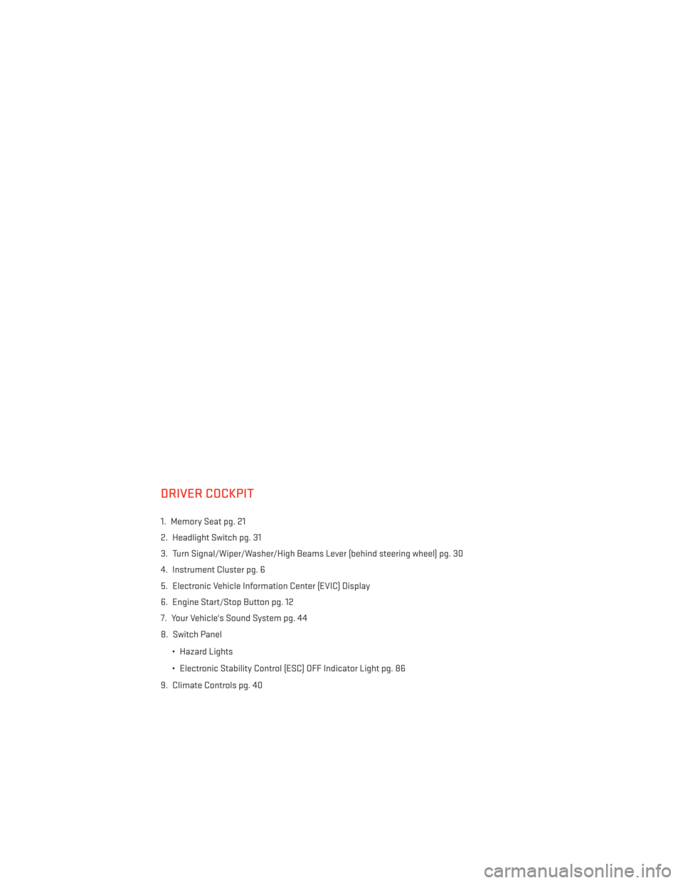
DRIVER COCKPIT
1. Memory Seat pg. 21
2. Headlight Switch pg. 31
3. Turn Signal/Wiper/Washer/High Beams Lever (behind steering wheel) pg. 30
4. Instrument Cluster pg. 6
5. Electronic Vehicle Information Center (EVIC) Display
6. Engine Start/Stop Button pg. 12
7. Your Vehicle's Sound System pg. 44
8. Switch Panel• Hazard Lights
• Electronic Stability Control (ESC) OFF Indicator Light pg. 86
9. Climate Controls pg. 40
CONTROLS AT A GLANCE
4
Page 9 of 148
4. Fuel Gauge
5. Speedometer
6. Fuel Filler Location
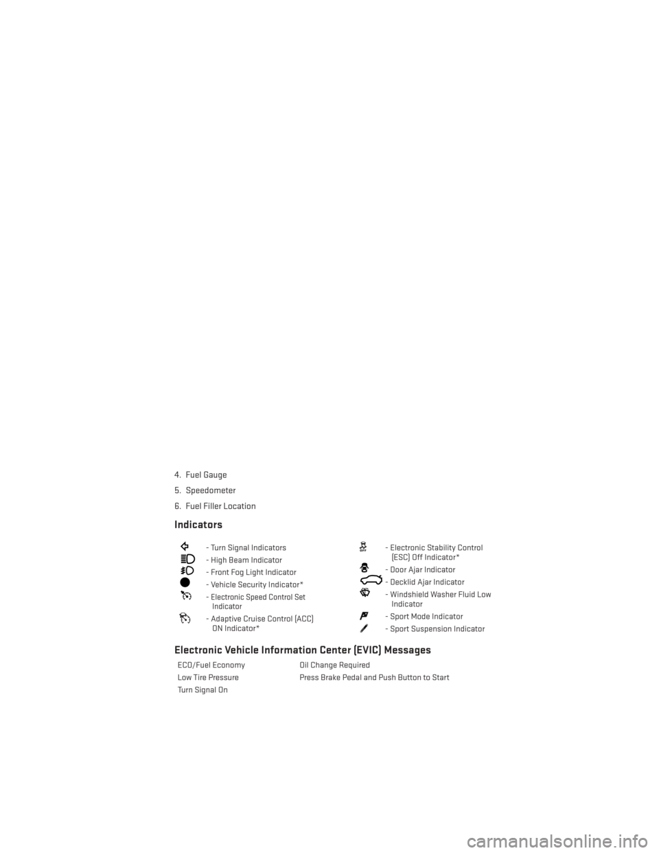
Indicators
- Turn Signal Indicators
- High Beam Indicator
- Front Fog Light Indicator
- Vehicle Security Indicator*
-Electronic Speed Control SetIndicator
- Adaptive Cruise Control (ACC)
ON Indicator*
- Electronic Stability Control(ESC) Off Indicator*
- Door Ajar Indicator
- Decklid Ajar Indicator
- Windshield Washer Fluid LowIndicator
- Sport Mode Indicator
- Sport Suspension Indicator
Electronic Vehicle Information Center (EVIC) Messages
ECO/Fuel Economy Oil Change Required
Low Tire Pressure Press Brake Pedal and Push Button to Start
Turn Signal On
CONTROLS AT A GLANCE
7
Page 10 of 148
KEY FOB
Locking And Unlocking The Doors
• Push and release the LOCK button on theRKE transmitter to lock all doors. The turn
signal lights will flash and the horn will
chirp to acknowledge the signal.
• Push and release the UNLOCK button on the RKE transmitter once to unlock the
driver's door or twice within five seconds
to unlock all doors. The turn signal lights
will flash to acknowledge the unlock sig-
nal. The illuminated entry system will also
turn on.
1st Push Of Key Fob Unlocks
This feature lets you program the system to
unlock either the driver's door or all doors on
the first push of the UNLOCK button on the
RKE transmitter. To change the current set-
ting, refer to your Owner's Manual on the DVD
for further information.
Opening The Trunk
• Press the Trunk Release button on the transmitter two times within five seconds to open the trunk.
Panic Alarm
• Press the PANIC button once to turn the panic alarm on.
• Wait approximately three seconds and press the button a second time to turn the panicalarm off.
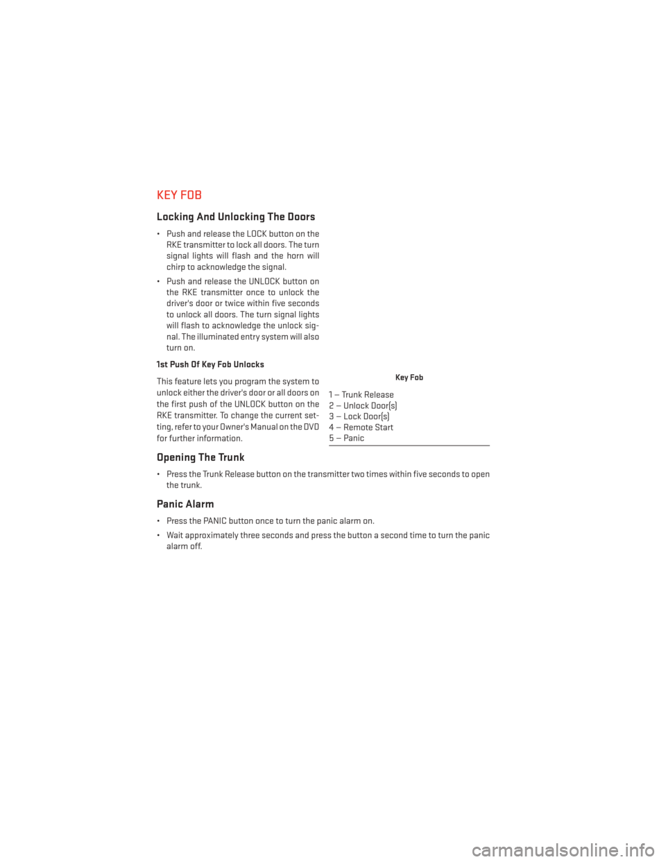
Key Fob
1 — Trunk Release
2 — Unlock Door(s)
3 — Lock Door(s)
4 — Remote Start
5 — Panic
GETTING STARTED
8
Page 30 of 148
TILT/TELESCOPING STEERING COLUMN
Manual Tilt/Telescoping Steering Column
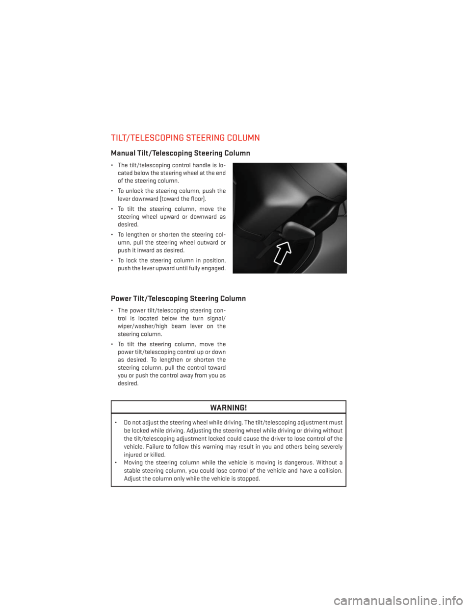
• The tilt/telescoping control handle is lo-cated below the steering wheel at the end
of the steering column.
• To unlock the steering column, push the lever downward (toward the floor).
• To tilt the steering column, move the steering wheel upward or downward as
desired.
• To lengthen or shorten the steering col- umn, pull the steering wheel outward or
push it inward as desired.
• To lock the steering column in position, push the lever upward until fully engaged.
Power Tilt/Telescoping Steering Column
• The power tilt/telescoping steering con-trol is located below the turn signal/
wiper/washer/high beam lever on the
steering column.
• To tilt the steering column, move the power tilt/telescoping control up or down
as desired. To lengthen or shorten the
steering column, pull the control toward
you or push the control away from you as
desired.
WARNING!
• Do not adjust the steering wheel while driving. The tilt/telescoping adjustment must
be locked while driving. Adjusting the steering wheel while driving or driving without
the tilt/telescoping adjustment locked could cause the driver to lose control of the
vehicle. Failure to follow this warning may result in you and others being severely
injured or killed.
• Moving the steering column while the vehicle is moving is dangerous. Without a
stable steering column, you could lose control of the vehicle and have a collision.
Adjust the column only while the vehicle is stopped.
GETTING STARTED
28
Page 32 of 148
CAUTION!
Never use Non-Detergent Oil or Straight Mineral Oil in the engine or damage may result.
TURN SIGNAL/WIPER/WASHER/HIGH BEAM LEVER
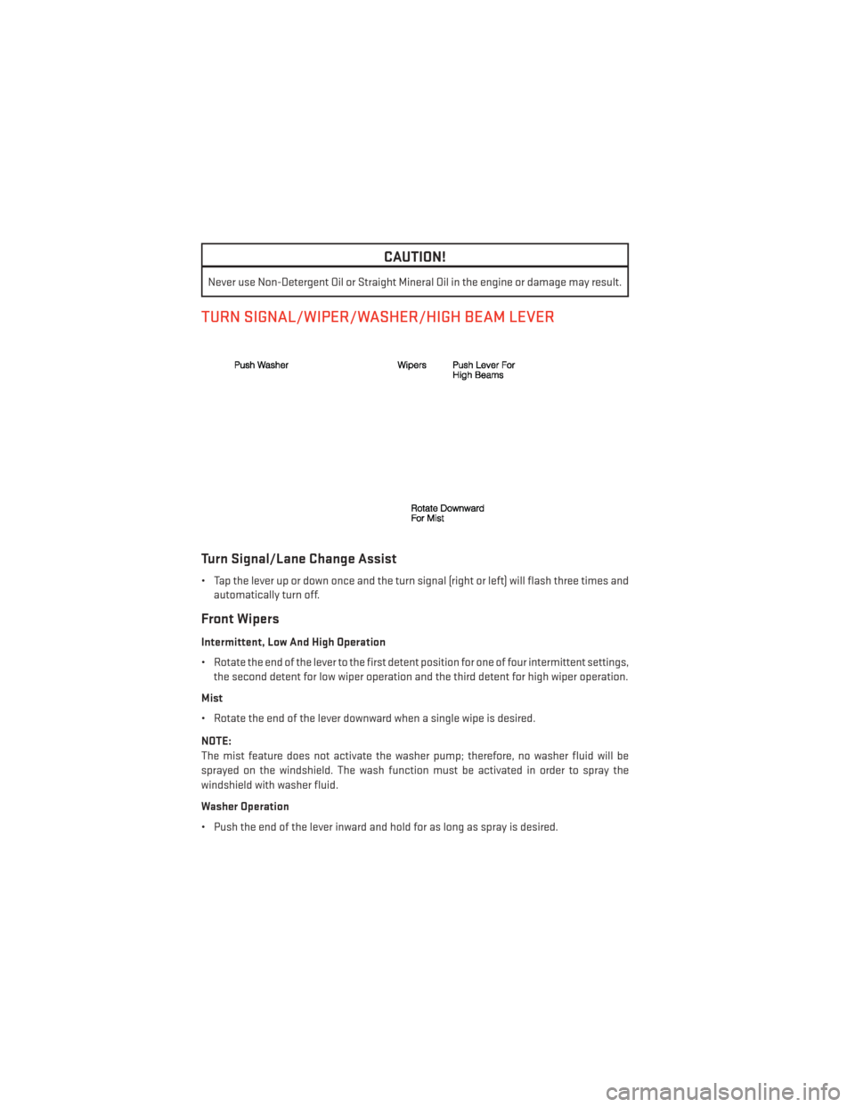
Turn Signal/Lane Change Assist
• Tap the lever up or down once and the turn signal (right or left) will flash three times andautomatically turn off.
Front Wipers
Intermittent, Low And High Operation
• Rotate the end of the lever to the first detent position for one of four intermittent settings,the second detent for low wiper operation and the third detent for high wiper operation.
Mist
• Rotate the end of the lever downward when a single wipe is desired.
NOTE:
The mist feature does not activate the washer pump; therefore, no washer fluid will be
sprayed on the windshield. The wash function must be activated in order to spray the
windshield with washer fluid.
Washer Operation
• Push the end of the lever inward and hold for as long as spray is desired.
OPERATING YOUR VEHICLE
30
Page 58 of 148
GARMIN® NAVIGATION
Garmin® Navigation (8.4N Only)
• Uconnect® 8.4N integrates Garmin’s consumer-friendly navigation into your vehicle.Garmin Navigation includes Lane Assist and Junction View, Speed Limit information,
and a database with over 6 million points of interest.
• Touch the “Nav” soft-key in the menu bar to access the Navigation system.
Changing The Navigation Voice Prompt Volume
1. Program a destination.
2. While traveling on your route, touch the upper left area of the map screen where your next turn is displayed.
3. The Navigation system will then repeat the distance to your next turn.
4. While the Navigation system is speaking, use the ON/OFF VOLUME rotary knob to adjust the volume to a comfortable level. Please note the volume setting for Navigation Voice
Prompt is different than the audio system.
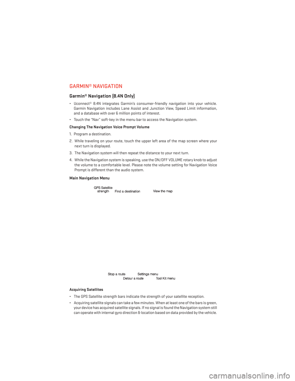
Main Navigation Menu
Acquiring Satellites
• The GPS Satellite strength bars indicate the strength of your satellite reception.
• Acquiring satellite signals can take a few minutes. When at least one of the bars is green,your device has acquired satellite signals. If no signal is found the Navigation system still
can operate with internal gyro direction & location based on data provided by the vehicle.
ELECTRONICS
56
Page 76 of 148
3. Simultaneously press and hold both the HomeLink® button you want to program and thehand-held transmitter button.
4. Continue to hold both buttons and observe the indicator light. The HomeLink® indicator will flash slowly and then rapidly after HomeLink® has received the frequency signal
from the hand-held transmitter. Release both buttons after the indicator light changes
from slow to rapid.
5. At the garage door opener motor (in the garage), locate the “LEARN” or “TRAINING” button. This can usually be found where the hanging antenna wire is attached to the
garage door opener motor. Firmly press and release the “LEARN” or “TRAINING” button.
NOTE:
You have 30 seconds in which to initiate the next step after the LEARN button has been
pressed.
6. Return to the vehicle and press the programmed HomeLink® button twice (holding the button for two seconds each time). If the device is plugged in and activates, program-
ming is complete.
NOTE:
If the device does not activate, press the button a third time (for two seconds) to complete
the training.
7. To program the remaining two HomeLink® buttons, repeat each step for each remaining button. DO NOT erase the channels.
Programming A Non-Rolling Code
NOTE:
For programming Garage Door Openers manufactured before 1995.
1. Turn the ignition switch to the ON/RUN position.
2. Place the hand-held transmitter 1 to 3 inches (3 to 8 cm) away from the HomeLink® button you wish to program while keeping the HomeLink® indicator light in view.
3. Simultaneously press and hold both the HomeLink® button you want to program and the hand-held transmitter button.
4. Continue to hold both buttons and observe the indicator light. The HomeLink® indicator will flash slowly and then rapidly after HomeLink® has received the frequency signal
from the hand-held transmitter. Release both buttons after the indicator light changes
from slow to rapid.
5. Press and hold the programmed HomeLink® button and observe the indicator light. If the indicator light stays on constantly, programming is complete and the garage door (or
device) should activate when the HomeLink® button is pressed.
6. To program the two remaining HomeLink® buttons, repeat each step for each remaining button. DO NOT erase the channels.
ELECTRONICS
74
Page 87 of 148
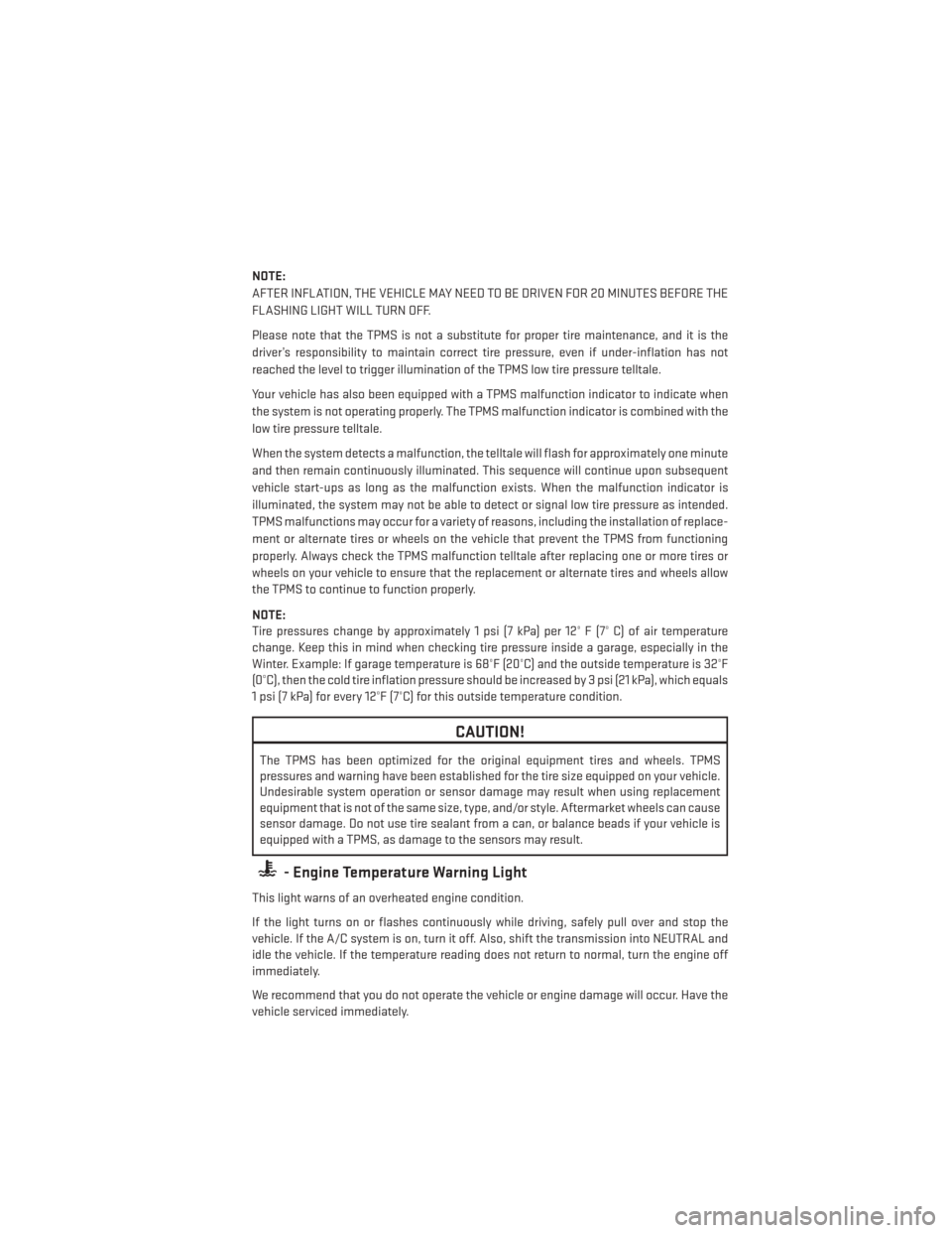
NOTE:
AFTER INFLATION, THE VEHICLE MAY NEED TO BE DRIVEN FOR 20 MINUTES BEFORE THE
FLASHING LIGHT WILL TURN OFF.
Please note that the TPMS is not a substitute for proper tire maintenance, and it is the
driver’s responsibility to maintain correct tire pressure, even if under-inflation has not
reached the level to trigger illumination of the TPMS low tire pressure telltale.
Your vehicle has also been equipped with a TPMS malfunction indicator to indicate when
the system is not operating properly. The TPMS malfunction indicator is combined with the
low tire pressure telltale.
When the system detects a malfunction, the telltale will flash for approximately one minute
and then remain continuously illuminated. This sequence will continue upon subsequent
vehicle start-ups as long as the malfunction exists. When the malfunction indicator is
illuminated, the system may not be able to detect or signal low tire pressure as intended.
TPMS malfunctions may occur for a variety of reasons, including the installation of replace-
ment or alternate tires or wheels on the vehicle that prevent the TPMS from functioning
properly. Always check the TPMS malfunction telltale after replacing one or more tires or
wheels on your vehicle to ensure that the replacement or alternate tires and wheels allow
the TPMS to continue to function properly.
NOTE:
Tire pressures change by approximately 1 psi (7 kPa) per 12° F (7° C) of air temperature
change. Keep this in mind when checking tire pressure inside a garage, especially in the
Winter. Example: If garage temperature is 68°F (20°C) and the outside temperature is 32°F
(0°C), then the cold tire inflation pressure should be increased by 3 psi (21 kPa), which equals
1 psi (7 kPa) for every 12°F (7°C) for this outside temperature condition.
CAUTION!
The TPMS has been optimized for the original equipment tires and wheels. TPMS
pressures and warning have been established for the tire size equipped on your vehicle.
Undesirable system operation or sensor damage may result when using replacement
equipment that is not of the same size, type, and/or style. Aftermarket wheels can cause
sensor damage. Do not use tire sealant from a can, or balance beads if your vehicle is
equipped with a TPMS, as damage to the sensors may result.
- Engine Temperature Warning Light
This light warns of an overheated engine condition.
If the light turns on or flashes continuously while driving, safely pull over and stop the
vehicle. If the A/C system is on, turn it off. Also, shift the transmission into NEUTRAL and
idle the vehicle. If the temperature reading does not return to normal, turn the engine off
immediately.
We recommend that you do not operate the vehicle or engine damage will occur. Have the
vehicle serviced immediately.
WHAT TO DO IN EMERGENCIES
85
Page 133 of 148
WHEEL AND WHEEL TRIM CARE
All wheels and wheel trim, especially aluminum and chrome plated wheels, should be
cleaned regularly with a mild soap and water to prevent corrosion.
To remove heavy soil and/or excessive brake dust, use MOPAR® Wheel Cleaner or equiva-
lent or select a non-abrasive, non-acidic cleaner.
CAUTION!
Do not use scouring pads, steel wool, a bristle brush, or metal polishes. Do not use oven
cleaner. These products may damage the wheel's protective finish. Avoid automatic car
washes that use acidic solutions or harsh brushes that may damage the wheel's protec-
tive finish. Only MOPAR® Wheel Cleaner or equivalent is recommended.
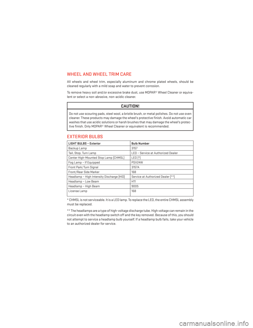
EXTERIOR BULBS
LIGHT BULBS – ExteriorBulb Number
Backup Lamp 3157
Tail, Stop, Turn Lamp LED – Service at Authorized Dealer
Center High-Mounted Stop Lamp (CHMSL) LED (*)
Fog Lamp – If Equipped PSX24W
Front Park/Turn Signal 3157A
Front/Rear Side Marker 168
Headlamp – High Intensity Discharge (HID) Service at Authorized Dealer (**)
Headlamp – Low Beam H11
Headlamp – High Beam 9005
License Lamp 168
* CHMSL is not serviceable. It is a LED lamp. To replace the LED, the entire CHMSL assembly
must be replaced.
** The headlamps are a type of high-voltage discharge tube. High voltage can remain in the
circuit even with the headlamp switch off and the key removed. Because of this, you should
not attempt to service a headlamp bulb yourself. If a headlamp bulb fails, take your vehicle
to an authorized dealer for service.
MAINTAINING YOUR VEHICLE
131