key DODGE CHARGER 2015 7.G Owner's Guide
[x] Cancel search | Manufacturer: DODGE, Model Year: 2015, Model line: CHARGER, Model: DODGE CHARGER 2015 7.GPages: 638, PDF Size: 16.56 MB
Page 148 of 638
WARNING!
•Be certain that the seatback is securely locked into
position. If the seatback is not securely locked into
position, the seat will not provide the proper sta-
bility for child seats and/or passengers. An improp-
erly latched seat could cause serious injury.
•The cargo area in the rear of the vehicle (with the
rear seatbacks in the locked-up or folded down
position) should not be used as a play area by
children when the vehicle is in motion. They could
be seriously injured in a collision. Children should
be seated and using the proper restraint system.
DRIVER MEMORY SEAT — IF EQUIPPED
This feature allows the driver to store up to two different
memory profiles for easy recall through a memory
switch. Each memory profile contains desired position
settings for the driver seat, side mirrors, adjustable
pedals (if equipped), and power tilt and telescopic steer-
ing column (if equipped) and a set of desired radio
station presets. Your Remote Keyless Entry (RKE) trans-
mitter can also be programmed to recall the same posi-
tions when the UNLOCK button is pushed.
NOTE:If your vehicle is equipped with two RKE trans-
mitters, one RKE transmitter can be linked to memory
position 1 and the other transmitter can be linked to
memory position 2.
146 UNDERSTANDING THE FEATURES OF YOUR VEHICLE
Page 150 of 638

NOTE:
•Memory profiles can be set without the vehicle in
PARK, but the vehicle must be in PARK to recall a
memory profile.
•To set a memory profile to your RKE transmitter, refer
to “Linking And Unlinking The Remote Keyless Entry
Transmitter To Memory” in this section.
Linking And Unlinking The Remote Keyless Entry
Transmitter To Memory
Your RKE transmitters can be programmed to recall one
of two pre-programmed memory profiles by pushing the
UNLOCK button on the RKE transmitter.
NOTE:Before programming your RKE transmitters you
must select the “Memory To FOB” or “Personal Settings
Linked To Fob” feature through the Uconnect® system
screen. Refer to “Uconnect® Settings” in “Understanding
Your Instrument Panel” for further information.
To program your RKE transmitters, perform the follow-
ing:
1. Place the vehicles ignition to the OFF position.
2. Select desired memory profile (1) or (2). The system
will recall any stored settings for this profile. Wait for
the system to complete the memory recall before
continuing to Step 3.
NOTE:If a memory profile has not already been set,
refer to#Programming The Memory Feature#in this
section for instructions on how to set a memory profile.
3. Once the profile has been recalled, push and release
the SET (S) button on the memory switch, then push
and release button (1) or (2) accordingly. “Memory
Profile Set” (1 or 2) will display in the Drivers Infor-
mation Display (DID).
4. Push and release the LOCK button on the RKE trans-
mitter within 10 seconds.
148 UNDERSTANDING THE FEATURES OF YOUR VEHICLE
Page 151 of 638

NOTE:Your RKE transmitters can be unlinked from
your memory settings by pushing the SET (S) button, and
within 10 seconds, followed by pushing the UNLOCK
button on the RKE transmitter.
Memory Position Recall
NOTE:The vehicle must be in PARK to recall memory
positions. If a recall is attempted when the vehicle is not
in PARK, a message will display in the Drivers Informa-
tion Display (DID).
To recall the memory settings for driver 1, push
MEMORY button number 1 on the driver’s door or the
UNLOCK button on the RKE transmitter linked to
memory position 1.
NOTE:If the vehicle is equipped with Passive Entry, the
memory settings will be recalled with a Passive Entry
Unlock into the driver’s door using the Key Fob linked to
position 1.
To recall the memory setting for driver 2, push MEMORY
button number 2 on the driver’s door or the UNLOCK
button on the RKE transmitter linked to memory position 2.
NOTE:If the vehicle is equipped with Passive Entry, the
memory settings will be recalled with a Passive Entry
Unlock into the driver’s door using the Key Fob linked to
position 2.
A recall can be cancelled by pushing any of the MEMORY
buttons (S, 1, or 2) on the driver’s door during a recall.
When a recall is cancelled, the driver’s seat, adjustable
pedals (if equipped), and power tilt and telescopic steer-
ing column (if equipped) stop moving. A delay of one
second will occur before another recall can be selected.
Easy Entry/Exit Seat
This feature provides automatic driver seat positioning to
enhance driver mobility when entering and exiting the
vehicle.
3
UNDERSTANDING THE FEATURES OF YOUR VEHICLE 149
Page 172 of 638
NOTE:For vehicles equipped with Driver Memory Seat,
you can use your Remote Keyless Entry (RKE) transmit-
ter or the memory switch on the driver’s door trim panel
to return the tilt/telescopic steering column to pre-
programmed positions. Refer to “Driver Memory Seat”
in this section.
WARNING!
Do not adjust the steering column while driving.
Adjusting the steering column while driving or driv-
ing with the steering column unlocked, could cause
the driver to lose control of the vehicle. Failure to
follow this warning may result in serious injury or
death.
HEATED STEERING WHEEL — IF EQUIPPED
The steering wheel contains a heating element that helps
warm your hands in cold weather. The heated steering
wheel has only one temperature setting. Once the heated
steering wheel has been turned on it will operate for up
to 80 minutes before automatically shutting off. The
heated steering wheel can shut off early or may not turn
on when the steering wheel is already warm.
The heated steering wheel control button is located
within the Uconnect® system. You can gain access to the
control button through the climate screen or the controls
screen.
•Push the heated steering wheel buttononce to turn
the heating element ON.
•Push the heated steering wheel buttona second
time to turn the heating element OFF.
170 UNDERSTANDING THE FEATURES OF YOUR VEHICLE
Page 175 of 638
•The pedalscannotbe adjusted when the vehicle is in
REVERSE or when the Electronic Speed Control Sys-
tem is on. The following messages will be displayed on
vehicles equipped with the Driver Information Dis-
play (DID) if the pedals are attempted to be adjusted
when the system is locked out (“Adjustable Pedal
Disabled — Cruise Control Engaged” or “Adjustable
Pedal Disabled — Vehicle In Reverse”).
NOTE:
•Always adjust the pedals to a position that allows full
pedal travel.
•Further small adjustments may be necessary to find
the best possible seat/pedal position.
•For vehicles equipped with Driver Memory Seat, you
can use your Remote Keyless Entry (RKE) transmitter
or the memory switch on the driver ’s door trim panel
to return the adjustable pedals to pre-programmed
positions. Refer to “Driver Memory Seat” in “Under-
standing The Features Of Your Vehicle” for further
information.
CAUTION!
Do not place any article under the adjustable pedals
or impede its ability to move as it may cause damage
to the pedal controls. Pedal travel may become lim-
ited if movement is stopped by an obstruction in the
adjustable pedal’s path.
WARNING!
Do not adjust the pedals while the vehicle is moving.
You could lose control and have an accident. Always
adjust the pedals while the vehicle is parked.
3
UNDERSTANDING THE FEATURES OF YOUR VEHICLE 173
Page 243 of 638
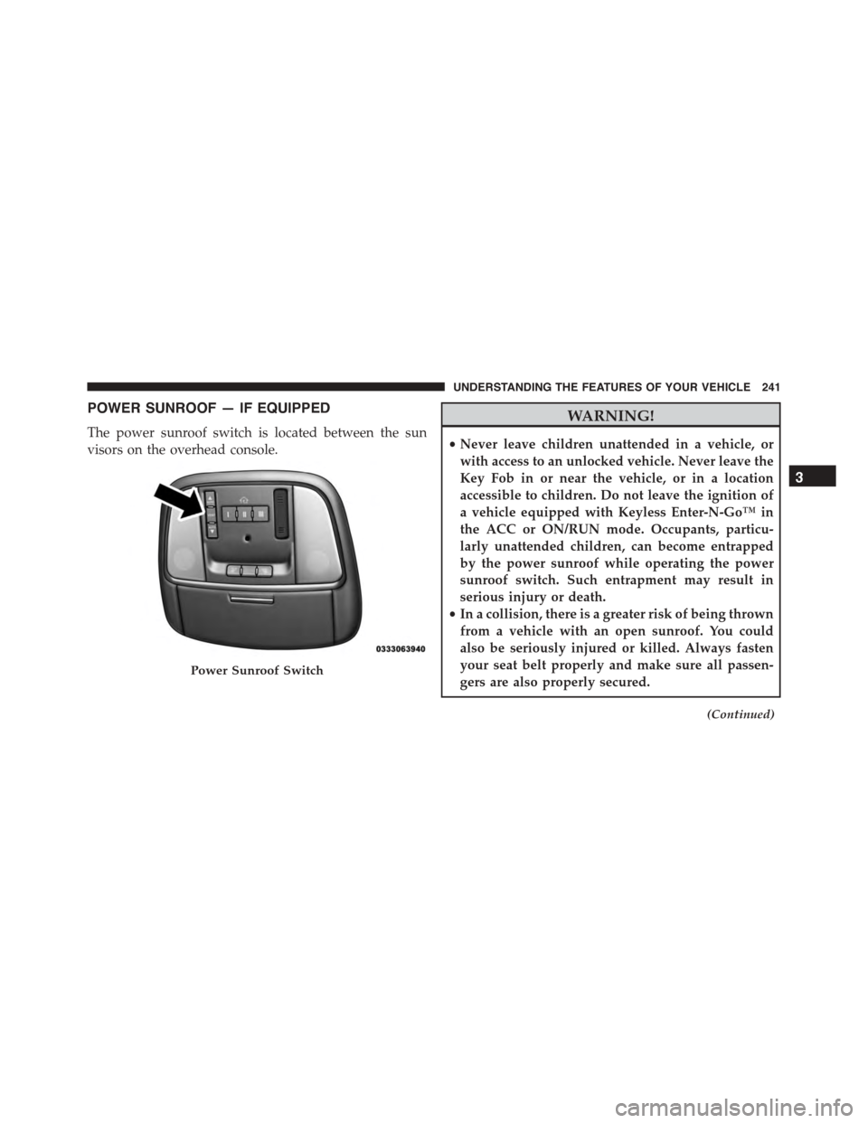
POWER SUNROOF — IF EQUIPPED
The power sunroof switch is located between the sun
visors on the overhead console.
WARNING!
•Never leave children unattended in a vehicle, or
with access to an unlocked vehicle. Never leave the
Key Fob in or near the vehicle, or in a location
accessible to children. Do not leave the ignition of
a vehicle equipped with Keyless Enter-N-Go™ in
the ACC or ON/RUN mode. Occupants, particu-
larly unattended children, can become entrapped
by the power sunroof while operating the power
sunroof switch. Such entrapment may result in
serious injury or death.
•In a collision, there is a greater risk of being thrown
from a vehicle with an open sunroof. You could
also be seriously injured or killed. Always fasten
your seat belt properly and make sure all passen-
gers are also properly secured.
(Continued)
Power Sunroof Switch
3
UNDERSTANDING THE FEATURES OF YOUR VEHICLE 241
Page 246 of 638

Sunroof Maintenance
Use only a non-abrasive cleaner and a soft cloth to clean
the glass panel.
Ignition Off Operation
NOTE:
•The power sunroof switch can remain active for up to
approximately ten minutes after the vehicles ignition is
placed to the Off position. Opening either front door
will cancel this feature.
•This feature is programmable using the Uconnect®
System. Refer to “Uconnect® Settings” in “Under-
standing Your Instrument Panel” for further informa-
tion.
ELECTRICAL POWER OUTLETS
Your vehicle is equipped with one 12 Volt (13 Amp)
power outlet on the instrument panel and one 12 Volt (10
Amp) power outlet in the center console that can be used
to power cellular phones, small electronics and other low
powered electrical accessories. The power outlets are
labeled with either a “key” or a “battery” symbol to
indicate how the outlet is powered. Power outlets labeled
with a “key” are powered when the ignition switch is in
the ON or ACC position, while the outlets labeled with a
“battery” are connected directly to the battery and pow-
ered at all times.
244 UNDERSTANDING THE FEATURES OF YOUR VEHICLE
Page 273 of 638
bulb check or when driving. Refer to “Occupant Re-
straints” in “Things To Know Before Starting Your Ve-
hicle” for further information.
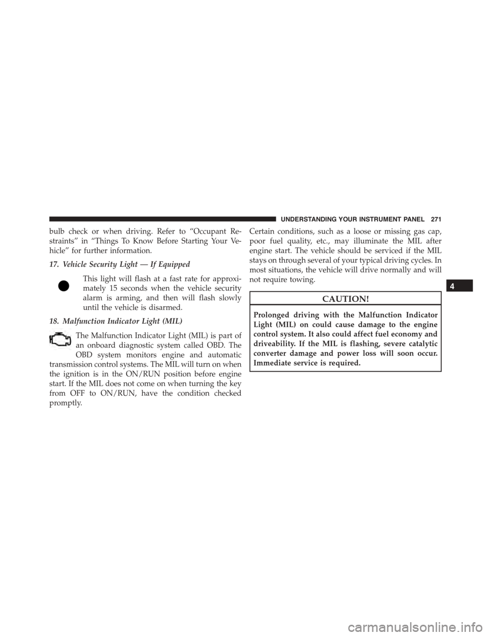
17. Vehicle Security Light — If Equipped
This light will flash at a fast rate for approxi-
mately 15 seconds when the vehicle security
alarm is arming, and then will flash slowly
until the vehicle is disarmed.
18. Malfunction Indicator Light (MIL)
The Malfunction Indicator Light (MIL) is part of
an onboard diagnostic system called OBD. The
OBD system monitors engine and automatic
transmission control systems. The MIL will turn on when
the ignition is in the ON/RUN position before engine
start. If the MIL does not come on when turning the key
from OFF to ON/RUN, have the condition checked
promptly.
Certain conditions, such as a loose or missing gas cap,
poor fuel quality, etc., may illuminate the MIL after
engine start. The vehicle should be serviced if the MIL
stays on through several of your typical driving cycles. In
most situations, the vehicle will drive normally and will
not require towing.
CAUTION!
Prolonged driving with the Malfunction Indicator
Light (MIL) on could cause damage to the engine
control system. It also could affect fuel economy and
driveability. If the MIL is flashing, severe catalytic
converter damage and power loss will soon occur.
Immediate service is required.
4
UNDERSTANDING YOUR INSTRUMENT PANEL 271
Page 277 of 638

•Pushing the left arrow button will exit each submenu
layer and return to the main menu.
For the Trip and Fuel Economy menus (and new Perfor-
mance Timers):
•Information is reset by pushing and holding the OK
button.
Engine Oil Life Reset
Oil Change Required
Your vehicle is equipped with an engine oil change
indicator system. The “Oil Change Required” message
will display in the DID for five seconds after a single
chime has sounded, to indicate the next scheduled oil
change interval. The engine oil change indicator system
is duty cycle based, which means the engine oil change
interval may fluctuate, dependent upon your personal
driving style.
Unless reset, this message will continue to display each
time you place the ignition in the ON/RUN position. To
turn off the message temporarily, push and release the
OK button. To reset the oil change indicator system (after
performing the scheduled maintenance), refer to the
following procedure.
Vehicles Equipped With Keyless Enter-N-Go™
1. Without pushing the brake pedal, push the ENGINE
START/STOP button and place the ignition to the
ON/RUN position (do not start the engine).
2. Fully push the accelerator pedal, slowly, three times
within 10 seconds.
3. Without pushing the brake pedal, push the ENGINE
START/STOP button once to return the ignition to the
OFF/LOCK position.
4
UNDERSTANDING YOUR INSTRUMENT PANEL 275
Page 282 of 638
vehicle is experiencing a problem with the charging
system. OBTAIN SERVICE IMMEDIATELY. See an au-
thorized dealer.
If jump starting is required, refer to “Jump Starting
Procedures” in “What To Do In Emergencies.”
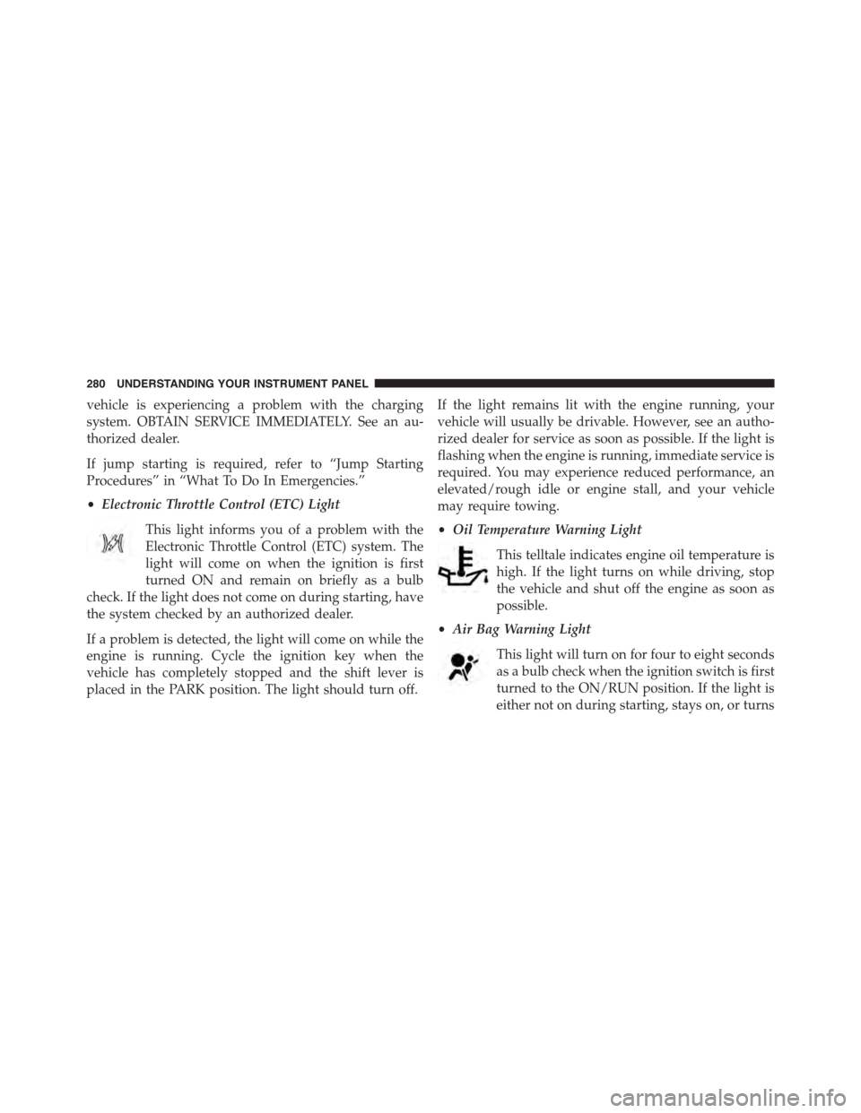
•Electronic Throttle Control (ETC) Light
This light informs you of a problem with the
Electronic Throttle Control (ETC) system. The
light will come on when the ignition is first
turned ON and remain on briefly as a bulb
check. If the light does not come on during starting, have
the system checked by an authorized dealer.
If a problem is detected, the light will come on while the
engine is running. Cycle the ignition key when the
vehicle has completely stopped and the shift lever is
placed in the PARK position. The light should turn off.
If the light remains lit with the engine running, your
vehicle will usually be drivable. However, see an autho-
rized dealer for service as soon as possible. If the light is
flashing when the engine is running, immediate service is
required. You may experience reduced performance, an
elevated/rough idle or engine stall, and your vehicle
may require towing.
•Oil Temperature Warning Light
This telltale indicates engine oil temperature is
high. If the light turns on while driving, stop
the vehicle and shut off the engine as soon as
possible.
•Air Bag Warning Light
This light will turn on for four to eight seconds
as a bulb check when the ignition switch is first
turned to the ON/RUN position. If the light is
either not on during starting, stays on, or turns
280 UNDERSTANDING YOUR INSTRUMENT PANEL