sensor DODGE CHARGER 2015 7.G User Guide
[x] Cancel search | Manufacturer: DODGE, Model Year: 2015, Model line: CHARGER, Model: DODGE CHARGER 2015 7.GPages: 236, PDF Size: 35.67 MB
Page 22 of 236
SUPPLEMENTAL RESTRAINT SYSTEM (SRS) — AIR BAGS
Air Bag System Components
Yo u r v e h i c l e m a y b e e q u i p p e d w i t h t h e f o l l o w i n g a i r b a g s y s t e m c o m p o n e n t s :
•OccupantRestraintController(ORC)
•AirBagWarningLight
•SteeringWheelandColumn
•InstrumentPanel
•KneeImpactBolsters
•AdvancedFrontAirBags
•SupplementalSideAirBags
•SupplementalKneeAirBags
•FrontandSideImpactSensors
•SeatBeltPretentioners
•SeatBeltBuckleSwitch
•SeatTrackPositionSensors
Advanced Front Air Bags
•ThisvehiclehasAdvancedFrontAirBagsforboththedriverandfrontpassengerasa
supplement to the seat belt restraint systems. The Advanced Front Air Bags will not
deploy in every type of collision.
•AdvancedFrontAirBagsaredesignedtoprovideadditionalprotectionbysupplement-
ing the seat belts. Advanced Front Air Bags are not expected to reduce the risk of injury
in rear, side, or rollover collisions.
•TheAdvancedFrontAirBagswillnotdeployinallfrontalcollisions,includingsome
that may produce substantial vehicle damage — for example, some pole collisions,
truck underrides, and angle offset collisions.
•Ontheotherhand,dependingonthetypeandlocationofimpact,AdvancedFrontAir
Bags may deploy in crashes with little vehicle front-end damage but that produce a
severe initial deceleration.
•Becauseairbagsensorsmeasurevehicledecelerationovertime,vehiclespeedand
damage by themselves are not good indicators of whether or not an air bag should have
deployed.
•Seatbeltsarenecessaryforyourprotectioninallcollisions,andalsoareneededtohelp
keep you in position, away from an inflating air bag.
•Theairbagsmustbereadytoinflateforyourprotectioninacollision.TheOccupant
Restraint Controller (ORC) monitors the internal circuits and interconnecting wiring
associated with air bag system electrical components.
GETTING STARTED
20
Page 47 of 236
ADAPTIVE CRUISE CONTROL (ACC)
If your vehicle is equipped with Adaptive
Cruise Control the controls operate exactly
the same as the electronic speed control
with only a couple of differences. With this
option you can set a specified distance you
would like to maintain between you and the
vehicle in front of you.
If the ACC sensor detects a vehicle ahead,
ACC will apply limited braking or accelera-
tion automatically to maintain a preset fol-
lowing distance, while matching the speed
of the vehicle ahead.
If the sensor does not detect a vehicle
ahead of you, ACC will maintain a fixed set
speed.
ACC ON/OFF
•PushandreleasetheAdaptiveCruise
Control (ACC) ON/OFF button.
ACC READY will appear in the Driver Information Display (DID) to indicate the ACC is on.
•PushandreleasetheAdaptiveCruiseControl(ACC)ON/OFFbuttonasecondtimeto
turn the system off.
Adaptive Cruise Control (ACC) Off will appear in the Driver Information Display (DID) to
indicate the ACC is off.
To Vary The Speed Setting
To Increase Speed
While ACC is set, you can increase the set speed by pushing the SET+button.
The drivers preferred units can be selected through the instrument panel settings if
equipped. Refer to “Understanding Your Instrument Panel” in the Owner’s Manual on
the DVD for more information. The speed increment shown is dependant on the speed of
U.S. (mph) or Metric (km/h) units:
U.S. Speed (mph)
•PushingtheSET+button once will result in a 1 mph increase in set speed. Each
subsequent tap of the button results in an increase of 1 mph.
•If the button is continually pushed, the set speed will continue to increase in 5 mph
increments until the button is released. The increase in set speed is reflected in the DID.
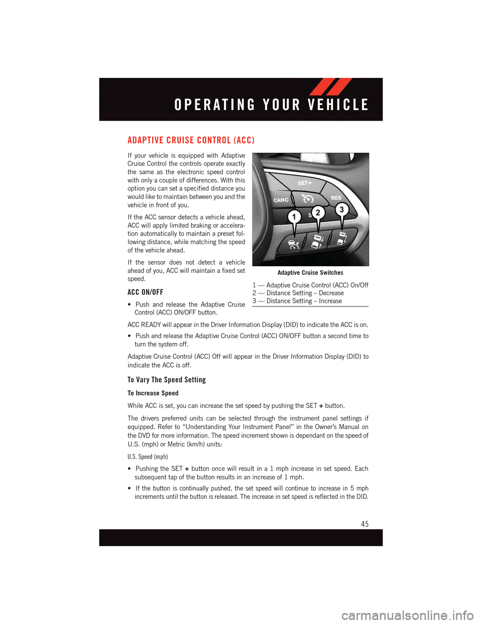
Adaptive Cruise Switches
1—AdaptiveCruiseControl(ACC)On/Off2—DistanceSetting–Decrease3—DistanceSetting–Increase
OPERATING YOUR VEHICLE
45
Page 51 of 236
FORWARD COLLISION WARNING (FCW) WITH MITIGATION
The Forward Collision Warning (FCW) system with mitigation provides the driver with audible
warnings, visual warnings (within the DID), and may apply a brake jerk to warn the driver
when it detects a potential frontal collision. The warnings and limited braking are intended to
provide the driver with enough time to react, avoid or mitigate the potential collision.
•FCWmonitorstheinformationfromtheforwardlookingsensorsaswellasthe
Electronic Brake Controller (EBC), to calculate the probability of a forward collision.
When the system determines that a forward collision is probable, the driver will be
provided with audible and visual warnings and may provide a brake jerk warning.
•Ifthedriverdoesnottakeactionbasedupontheseprogressivewarnings,thenthe
system will provide a limited level of active braking to help slow the vehicle and mitigate
the potential forward collision. If the driver reacts to the warnings by braking and the
system determines that the driver intends to avoid the collision by braking but has not
applied sufficient brake force, the system will compensate and provide additional brake
force as required.
Turning FCW ON Or OFF
NOTE:
The default status of FCW is “On,” this allows the system to warn you of a possible
collision with the vehicle in front of you when you are farther away and it applies limited
braking. This gives you the most reaction time to avoid a possible collision.
The forward collision button is on the switch panel that is located in the center of the
instrument panel.
•To t u r n t h e F C W s y s t e m O F F, p u s h t h e f o r w a r d c o l l i s i o n b u t t o n o n c e ( L E D t u r n s o n ) .
•To t u r n t h e F C W s y s t e m b a c k O N , p u s h t h e f o r w a r d c o l l i s i o n b u t t o n a g a i n ( L E D t u r n s o f f ) .
Changing FCW Status
The FCW feature has two settings and can be changed within the Uconnect®System
Screen:
•Far
•Near
NOTE:
The FCW and active braking settings can only be changed when the vehicle is in PARK.
Far
The default status of FCW is the “Far” setting.
The far setting provides warnings for potential collisions more distant in front of the
vehicle, allowing the driver to have the most reaction time to avoid a collision.
OPERATING YOUR VEHICLE
49
Page 54 of 236
PARKVIEW® REAR BACK-UP CAMERA
Yo u c a n s e e a n o n - s c r e e n i m a g e o f t h e r e a r o f y o u r v e h i c l e w h e n e v e r t h e t r a n s m i s s i o n i s
shifted into REVERSE. The ParkView®Rear Back-Up Camera image will be displayed on
the radio display screen, located on the center stack of the instrument panel.
If the radio display screen appears foggy, clean the camera lens located on the rear of the
vehicle above the rear license plate.
Refer to your Owner's Manual on the DVD for further details.
WARNING!
Drivers must be careful when backing up; even when using the ParkView®RearBack-Up Camera. Always check carefully behind your vehicle, and be sure to check forpedestrians, animals, other vehicles, obstructions, or blind spots before backing up.Yo u m u s t c o n t i n u e t o p a y a t t e n t i o n w h i l e b a c k i n g u p . F a i l u r e t o d o s o c a n r e s u l t i nserious injury or death.
BLIND SPOT MONITORING
The Blind Spot Monitoring (BSM) system uses two radar-based sensors, located inside the
rear bumper fascia, to detect Highway licensable vehicles (automobiles, trucks, motor-
cycles etc.) that enter the blind spot zones from the rear/front/side of the vehicle.
The Blind Spot Monitoring (BSM) system warning light, located in the outside mirrors, will
illuminate if a vehicle moves into a blind spot zone.
The BSM system can also be configured to sound an audible (chime) alert and mute the
radio to notify you of objects that have entered the detection zones.
Refer to “Blind Spot Monitoring” in “Understanding The Features Of Your Vehicle” in your
Owner's Manual on the DVD for further details.
OPERATING YOUR VEHICLE
52
Page 132 of 236
Taking A Detour
To t a k e a d e t o u r y o u m u s t b e n a v i g a t i n g a r o u t e .
•Pressthe“Detour”buttononthetouchscreen.
NOTE:
•Iftherouteyouarecurrentlytakingistheonlyreasonableoption,thedevicemightnot
calculate a detour.
•Formoreinformation,seeyourUconnect®Supplement Manual.
SiriusXM TRAFFIC (US Market Only)
Don't Drive Through Traffic. Drive Around It.
Avoid congestion before you reach it. By enhancing your vehicle's navigation system with
the ability to see detailed traffic information, you can pinpoint traffic incidents, determine
average traffic speed and estimate travel time along your route. Since the service is
integrated with a vehicle's navigation system, SiriusXM Traffic can help drivers pick the
fastest route based on traffic conditions.
•Detailedinformationontrafficspeed,accidents,construction,androadclosings.
•Trafficinformationfrommultiplesources,includingpoliceandemergencyservices,
cameras and road sensors.
•Coast-to-coastdeliveryoftrafficinformation.
•Viewconditionsforpointsalongyourrouteandbeyond.Availableinover130markets.
SiriusXM TRAVEL LINK (US Market Only)
In addition to delivering over 130 channels of the best sports, entertainment, talk, and
commercial-free music, SiriusXM offers premium data services that work in conjunction
with compatible navigation systems. SiriusXM Travel Link brings a wealth of useful
information into your vehicle and right to your fingertips.
•Fuel Prices—Checklocalgasanddieselpricesinyourareaandroutetothestationof
your choice.
•Movie Listings—Checklocalmovietheatresandlistingsinyourareaandroutetothe
theater of your choice.
•Sports Scores—In-gameandfinalscoresaswellasweeklyschedules.
•Weather—Checkvarietyoflocalandnationalweatherinformationfromradarmapsto
current and 5-day forecast.
ELECTRONICS
130
Page 163 of 236
When the system detects a malfunction, the telltale will flash for approximately one
minute and then remain continuously illuminated. This sequence will continue upon
subsequent vehicle start-ups as long as the malfunction exists. When the malfunction
indicator is illuminated, the system may not be able to detect or signal low tire pressure
as intended. TPMS malfunctions may occur for a variety of reasons, including the
installation of replacement or alternate tires or wheels on the vehicle that prevent the
TPMS from functioning properly. Always check the TPMS malfunction telltale after
replacing one or more tires or wheels on your vehicle to ensure that the replacement or
alternate tires and wheels allow the TPMS to continue to function properly.
NOTE:
Ti r e p r e s s u r e s c h a n g e b y a p p r o x i m a t e l y 1 p s i ( 7 k P a ) p e r 1 2 ° F ( 7 ° C ) o f a i r t e m p e r a t u r e
change. Keep this in mind when checking tire pressure inside a garage, especially in the
Winter. Example: If garage temperature is 68°F (20°C), and the outside temperature is
32°F (0°C), then the cold tire inflation pressure should be increased by 3 psi (21 kPa),
which equals 1 psi (7 kPa) for every 12°F (7°C) for this outside temperature condition.
CAUTION!
The TPMS has been optimized for the original equipment tires and wheels. TPMS
pressures and warning have been established for the tire size equipped on your vehicle.
Undesirable system operation or sensor damage may result when using replacement
equipment that is not of the same size, type, and/or style. Aftermarket wheels can
cause sensor damage. Do not use tire sealant from a can, or balance beads if your
vehicle is equipped with a TPMS, as damage to the sensors may result.
-EngineTemperatureWarningLight
This light warns of an overheated engine condition.
If the light turns on or flashes continuously while driving, safely pull over and stop the
vehicle. If the A/C system is on, turn it off. Also, shift the transmission into NEUTRAL and
idle the vehicle. If the temperature reading does not return to normal, turn the engine off
immediately.
We recommend that you do not operate the vehicle or engine damage will occur. Have the
vehicle serviced immediately.
WARNING!
Ahotenginecoolingsystemisdangerous.Youorotherscouldbebadlyburnedby
steam or boiling coolant.
WHAT TO DO IN EMERGENCIES
161
Page 166 of 236
-AdaptiveCruiseControl(ACC)ONIndicator
•If your vehicle is equipped with adaptive cruise control, the controls operate exactly the
same as the normal (fixed speed) cruise control with one difference. You can set a
specified distance you would like to maintain between you and the vehicle in front of you.
•IftheACCsensordetectsavehicleahead,ACCwillapplylimitedbrakingoraccelera-
tion automatically to maintain a preset following distance, while matching the speed of
the vehicle ahead.
•If the sensor does not detect a vehicle ahead of you, ACC will maintain a fixed set speed.
•Referto“SpeedControl”in“OperatingYourVehicle”forfurtherinformationon
Adaptive Cruise Control (ACC) ON operation and proper use.
NOTE:
Adaptive Cruise Control (ACC) increases the driving convenience provided by cruise
control while traveling on highways and major roadways. However, it is not a safety system
and not designed to prevent collisions.
Electronic Stability Control (ESC) OFF Indicator Light
This light indicates the Electronic Stability Control (ESC) is off.
-DoorAjarIndicator
This indicator will illuminate when a door(s) is left ajar and not fully closed.
Oil Change Due
Yo u r v e h i c l e i s e q u i p p e d w i t h a n e n g i n e o i l c h a n g e i n d i c a t o r s y s t e m . T h e “ O i l C h a n g e
Due” message will display for 5 seconds along with a single chime to indicate the next
scheduled oil change interval. The engine oil change indicator system is duty cycle based,
which means the engine oil change interval may fluctuate dependent upon your personal
driving style.
Resetting The Light After Servicing
Vehicles Equipped With Keyless Enter-N-Go™
1. Without pushing the brake pedal, push the ENGINE START/STOP button and cycle the
ignition to the ON/RUN position (do not start the engine).
2. Fully depress the accelerator pedal, slowly, three times within 10 seconds.
3. Without pushing the brake pedal, push the ENGINE START/STOP button once to
return the ignition to the OFF/LOCK position.
Vehicles Not Equipped With Keyless Enter-N-Go™
1. Turn the ignition switch to the ON/RUN position (do not start the engine).
2. Fully depress the accelerator pedal, slowly, three times within 10 seconds.
3. Turn the ignition switch to the OFF/LOCK position.
WHAT TO DO IN EMERGENCIES
164
Page 213 of 236
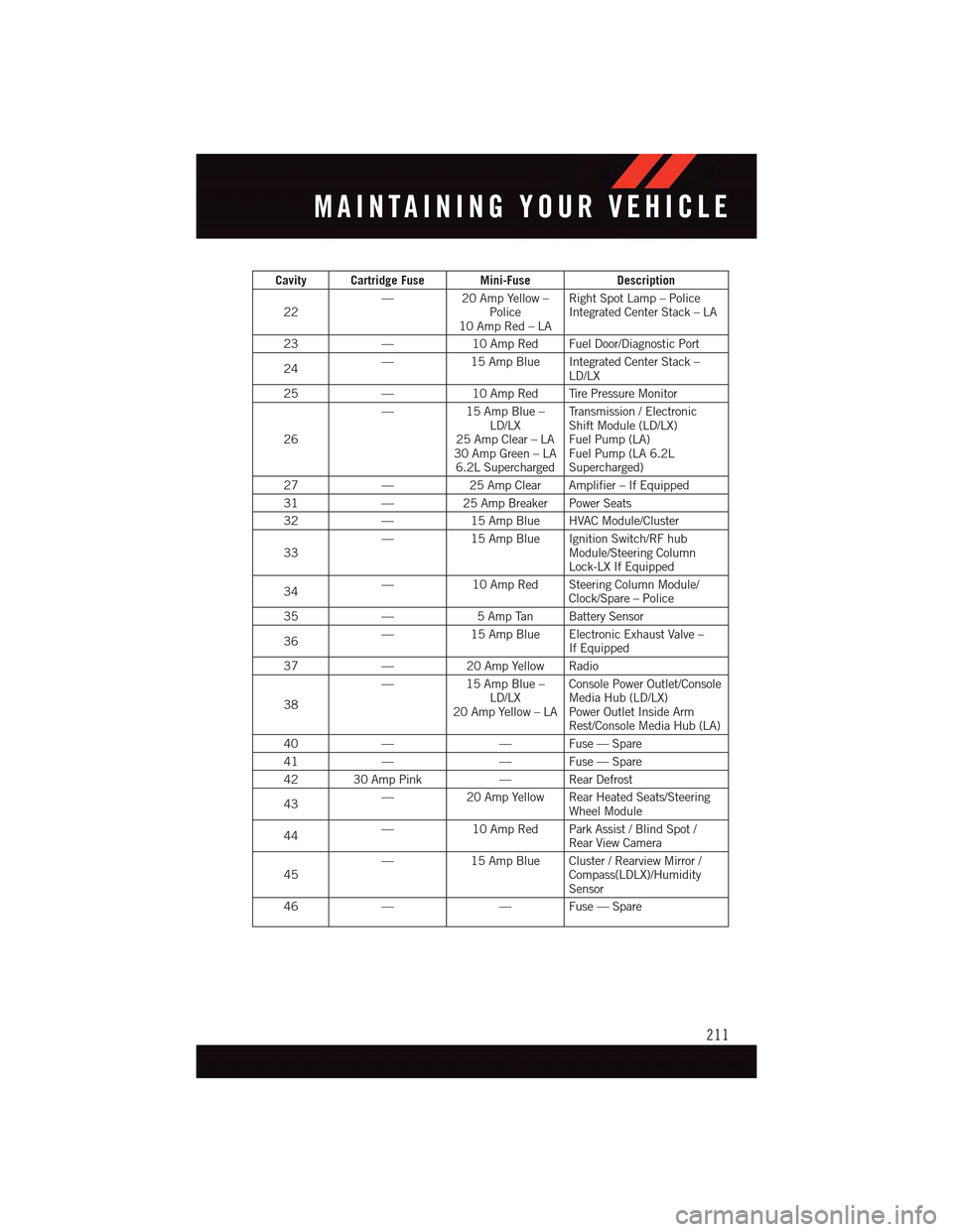
Cavity Cartridge Fuse Mini-FuseDescription
22—20 Amp Yellow –Police10 Amp Red – LA
Right Spot Lamp – PoliceIntegrated Center Stack – LA
23—10 Amp Red Fuel Door/Diagnostic Port
24—15 Amp Blue Integrated Center Stack –LD/LX
25—10 Amp Red Tire Pressure Monitor
26
—15 Amp Blue –LD/LX25 Amp Clear – LA30 Amp Green – LA6.2L Supercharged
Tr a n s m i s s i o n / E l e c t r o n i cShift Module (LD/LX)Fuel Pump (LA)Fuel Pump (LA 6.2LSupercharged)
27—25 Amp Clear Amplifier – If Equipped
31—25 Amp Breaker Power Seats
32—15 Amp Blue HVAC Module/Cluster
33—15 Amp Blue Ignition Switch/RF hubModule/Steering ColumnLock-LX If Equipped
34—10 Amp Red Steering Column Module/Clock/Spare – Police
35—5AmpTan BatterySensor
36—15 Amp Blue Electronic Exhaust Valve –If Equipped
37—20 Amp Yellow Radio
38
—15 Amp Blue –LD/LX20 Amp Yellow – LA
Console Power Outlet/ConsoleMedia Hub (LD/LX)Power Outlet Inside ArmRest/Console Media Hub (LA)
40——Fuse—Spare
41——Fuse—Spare
42 30 Amp Pink—RearDefrost
43—20 Amp Yellow Rear Heated Seats/SteeringWheel Module
44—10 Amp Red Park Assist / Blind Spot /Rear View Camera
45—15 Amp Blue Cluster / Rearview Mirror /Compass(LDLX)/HumiditySensor
46——Fuse—Spare
MAINTAINING YOUR VEHICLE
211
Page 214 of 236
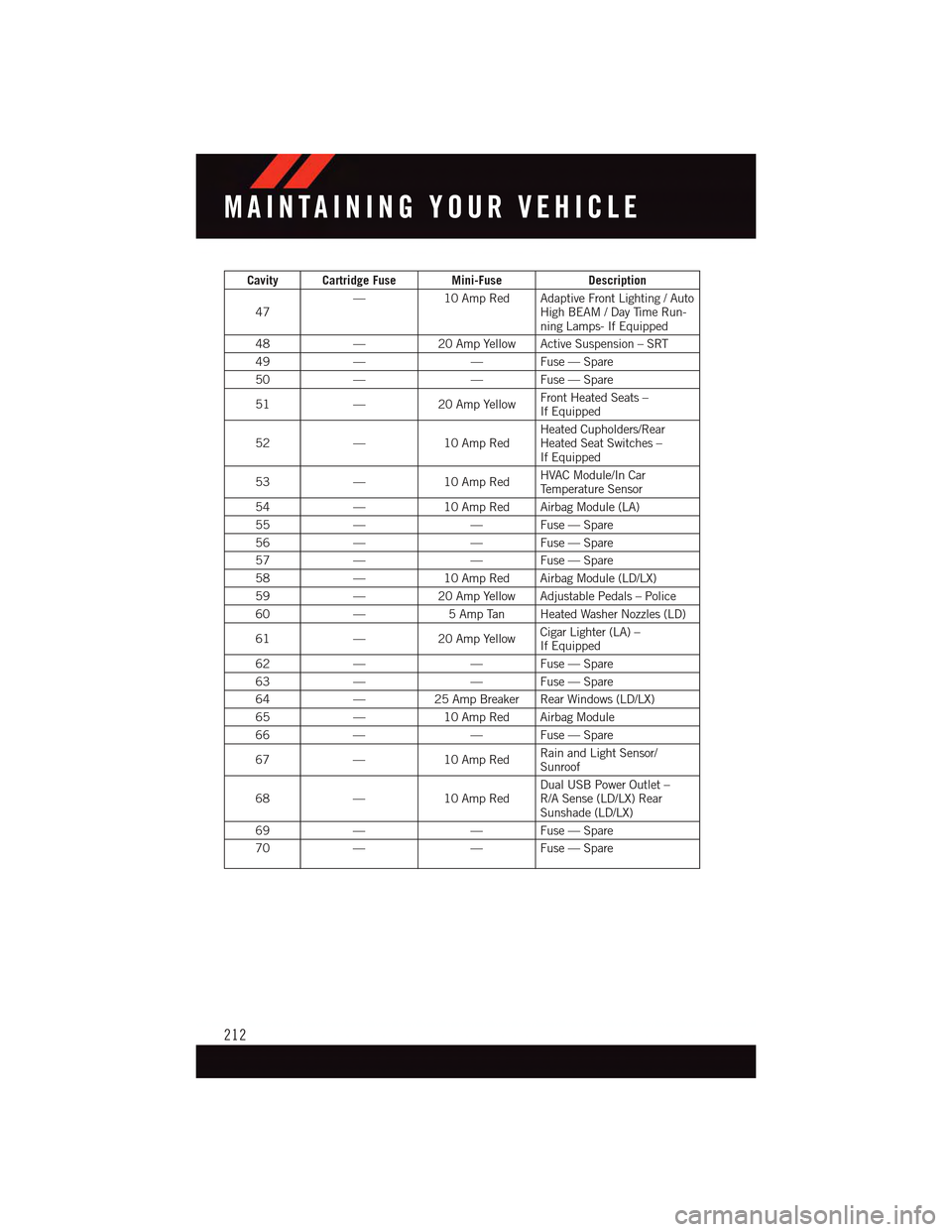
Cavity Cartridge Fuse Mini-FuseDescription
47—10 Amp Red Adaptive Front Lighting / AutoHigh BEAM / Day Time Run-ning Lamps- If Equipped
48—20 Amp Yellow Active Suspension – SRT
49——Fuse—Spare
50——Fuse—Spare
51—20 Amp YellowFront Heated Seats –If Equipped
52—10 Amp RedHeated Cupholders/RearHeated Seat Switches –If Equipped
53—10 Amp RedHVAC Module/In CarTe m p e r a t u r e S e n s o r
54—10 Amp Red Airbag Module (LA)
55——Fuse—Spare
56——Fuse—Spare
57——Fuse—Spare
58—10 Amp Red Airbag Module (LD/LX)
59—20 Amp Yellow Adjustable Pedals – Police
60—5AmpTan HeatedWasherNozzles(LD)
61—20 Amp YellowCigar Lighter (LA) –If Equipped
62——Fuse—Spare
63——Fuse—Spare
64—25 Amp Breaker Rear Windows (LD/LX)
65—10 Amp Red Airbag Module
66——Fuse—Spare
67—10 Amp RedRain and Light Sensor/Sunroof
68—10 Amp RedDual USB Power Outlet –R/A Sense (LD/LX) RearSunshade (LD/LX)
69——Fuse—Spare
70——Fuse—Spare
MAINTAINING YOUR VEHICLE
212