clutch DODGE CHARGER 2017 7.G Owners Manual
[x] Cancel search | Manufacturer: DODGE, Model Year: 2017, Model line: CHARGER, Model: DODGE CHARGER 2017 7.GPages: 530, PDF Size: 4.72 MB
Page 77 of 530
5. Remove slack in the tether strap according to the childrestraint manufacturer ’s instructions.
WARNING!
•An incorrectly anchored tether strap could lead to
increased head motion and possible injury to the
child. Use only the anchorage position directly be-
hind the child seat to secure a child restraint top
tether strap.
• If your vehicle is equipped with a split rear seat,
make sure the tether strap does not slip into the
opening between the seatbacks as you remove slack
in the strap.
Center Tether Attachment
1. Lower the adjustable center head restraint to the full down position.
2. Route the tether strap over the seatback and head restraint.
3. Attach the tether strap hook of the child restraint to the center tether anchorage located in the panel between the
rear seatback and the rear window. 4. Remove slack in the tether strap according to the child
restraint manufacturer ’s instructions.
Transporting Pets
Air Bags deploying in the front seat could harm your pet.
An unrestrained pet will be thrown about and possibly
injured, or injure a passenger during panic braking or in a
collision.
Pets should be restrained in the rear seat in pet harnesses or
pet carriers that are secured by seat belts.
ENGINE BREAK-IN RECOMMENDATIONS
For vehicles equipped with the 3.6L or 5.7L use the
following engine break-in recommendations:
A long break-in period is not required for the drivetrain
(engine, transmission, clutch, and rear axle) in your new
vehicle.
Drive moderately during the first 300 miles (500 km). After
the initial 60 miles (100 km), speeds up to 50 or 55 mph (80
or 90 km/h) are desirable.
2
THINGS TO KNOW BEFORE STARTING YOUR VEHICLE 75
Page 81 of 530
Air Bag Warning Light
The Air Bag Warning Lightwill turn on for four to
eight seconds as a bulb check when the ignition is first
placed in the ON/RUN position. If the light is either not
on during starting, stays on, or turns on while driving,
have the system inspected at an authorized dealer as
soon as possible. This light will illuminate with a single
chime when a fault with the Air Bag Warning Light has
been detected, it will stay on until the fault is cleared. If
the light comes on intermittently or remains on while
driving, have an authorized dealer service the vehicle
immediately. Refer to “Occupant Restraints” for further
information.
Defroster
Check operation by selecting the defrost mode and place
the blower control on high speed. You should be able to
feel the air directed against the windshield. See your
authorized dealer for service if your defroster is inoper-
able.
Floor Mat Safety Information
Always use floor mats designed to fit the footwell of your
vehicle. Use only floor mats that leave the pedal area
unobstructed and that are firmly secured so that they cannot slip out of position and interfere with the pedals or
impair safe operation of your vehicle in other ways.
WARNING!
An improperly attached, damaged, folded, or stacked
floor mat, or damaged floor mat fasteners may cause
your floor mat to interfere with the accelerator, brake,
or clutch pedals and cause a loss of vehicle control. To
prevent SERIOUS INJURY or DEATH:
•
ALWAYS securely attach
your floor mat using
the floor mat fasteners. DO NOT install your floor
mat upside down or turn your floor mat over.
Lightly pull to confirm mat is secured using the
floor mat fasteners on a regular basis.
• ALWAYS REMOVE THE EXISTING FLOOR MAT
FROM THE VEHICLE
before installing any
other floor mat. NEVER install or stack an addi-
tional floor mat on top of an existing floor mat.
•ONLY install floor mats designed to fit your vehicle.
NEVER install a floor mat that cannot be properly
attached and secured to your vehicle. If a floor mat
needs to be replaced, only use a FCA approved floor mat
for the specific make, model, and year of your vehicle.
(Continued)
2
THINGS TO KNOW BEFORE STARTING YOUR VEHICLE 79
Page 82 of 530
WARNING!(Continued)
•ONLY use the driver ’s side floor mat on the driver ’s side
floor area. To check for interference, with the vehicle
properly parked with the engine off, fully depress the
accelerator, the brake, and the clutch pedal (if present)
to check for interference. If your floor mat interferes
with the operation of any pedal, or is not secure to the
floor, remove the floor mat from the vehicle and place
the floor mat in your trunk.
• ONLY use the passenger ’s side floor mat on the
passenger ’s side floor area.
• ALWAYS make sure objects cannot fall or slide into
the driver ’s side floor area when the vehicle is
moving. Objects can become trapped under accelera-
tor, brake, or clutch pedals and could cause a loss of
vehicle control.
(Continued)
WARNING! (Continued)
•NEVER place any objects under the floor mat (e.g.,
towels, keys, etc.). These objects could change the
position of the floor mat and may cause interference
with the accelerator, brake, or clutch pedals.
• If the vehicle carpet has been removed and re-
installed, always properly attach carpet to the floor
and check the floor mat fasteners are secure to the
vehicle carpet. Fully depress each pedal to check for
interference with the accelerator, brake, or clutch
pedals then re-install the floor mats.
• It is recommended to only use mild soap and water
to clean your floor mats. After cleaning, always check
your floor mat has been properly installed and is
secured to your vehicle using the floor mat fasteners
by lightly pulling mat.
80 THINGS TO KNOW BEFORE STARTING YOUR VEHICLE
Page 357 of 530
Hill Start Assist (HSA)
The HSA system is designed to mitigate roll back from a
complete stop while on an incline. If the driver releases the
brake while stopped on an incline, HSA will continue to
hold the brake pressure for a short period. If the driver
does not apply the throttle before this time expires, the
system will release brake pressure and the vehicle will roll
down the hill as normal.
The following conditions must be met in order for HSA to
activate:
•The feature must be enabled.
• The vehicle must be stopped.
• Park brake must be off.
• Driver door must be closed.
• The vehicle must be on a sufficient grade.
• The gear selection must match vehicle uphill direction
(i.e., vehicle facing uphill is in forward gear; vehicle
backing uphill is in REVERSE gear). •
HSA will work in REVERSE gear and all forward gears.
The system will not activate if the transmission is in
PARK or NEUTRAL. For vehicles equipped with a
manual transmission, if the clutch is pressed, HSA will
remain active.
WARNING!
There may be situations where the Hill Start Assist
(HSA) will not activate and slight rolling may occur,
such as on minor hills or with a loaded vehicle, or
while pulling a trailer. HSA is not a substitute for
active driving involvement. It is always the driver ’s
responsibility to be attentive to distance to other ve-
hicles, people, and objects, and most importantly brake
operation to ensure safe operation of the vehicle under
all road conditions. Your complete attention is always
required while driving to maintain safe control of your
vehicle. Failure to follow these warnings can result in
a collision or serious personal injury.5
STARTING AND OPERATING 355
Page 476 of 530
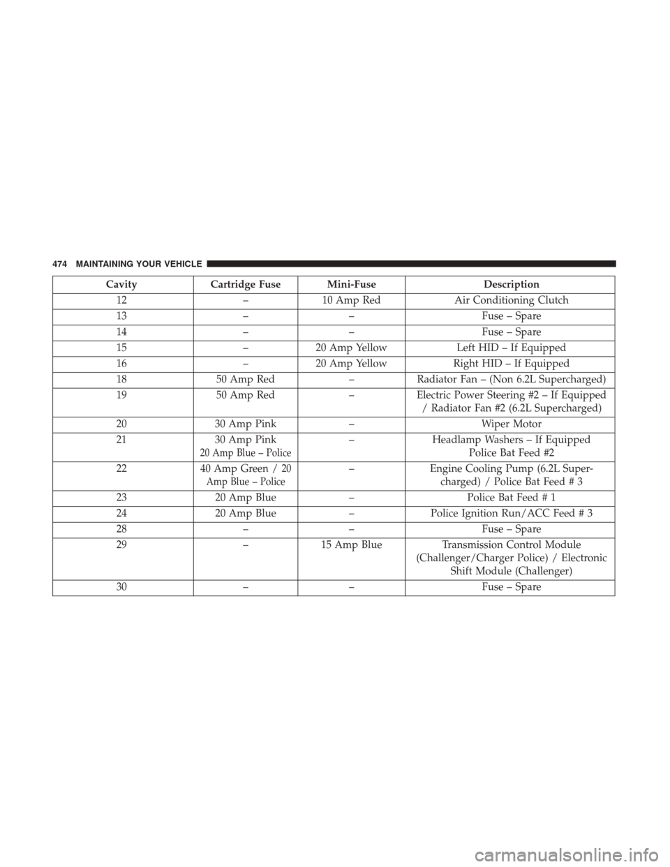
CavityCartridge Fuse Mini-Fuse Description
12 –10 Amp Red Air Conditioning Clutch
13 –– Fuse – Spare
14 –– Fuse – Spare
15 –20 Amp Yellow Left HID – If Equipped
16 –20 Amp Yellow Right HID – If Equipped
18 50 Amp Red –Radiator Fan – (Non 6.2L Supercharged)
19 50 Amp Red –Electric Power Steering #2 – If Equipped
/ Radiator Fan #2 (6.2L Supercharged)
20 30 Amp Pink –Wiper Motor
21 30 Amp Pink
20 Amp Blue – Police
–Headlamp Washers – If Equipped
Police Bat Feed #2
22 40 Amp Green /
20
Amp Blue – Police– Engine Cooling Pump (6.2L Super-
charged) / Police Bat Feed # 3
23 20 Amp Blue –Police Bat Feed # 1
24 20 Amp Blue –Police Ignition Run/ACC Feed # 3
28 –– Fuse – Spare
29 –15 Amp Blue Transmission Control Module
(Challenger/Charger Police) / Electronic Shift Module (Challenger)
30 –– Fuse – Spare
474 MAINTAINING YOUR VEHICLE
Page 477 of 530
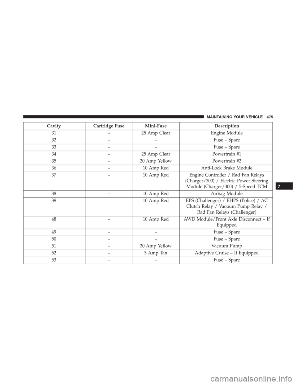
CavityCartridge Fuse Mini-Fuse Description
31 –25 Amp Clear Engine Module
32 –– Fuse – Spare
33 –– Fuse – Spare
34 –25 Amp Clear Powertrain #1
35 –20 Amp Yellow Powertrain #2
36 –10 Amp Red Anti-Lock Brake Module
37 –10 Amp Red Engine Controller / Rad Fan Relays
(Charger/300) / Electric Power SteeringModule (Charger/300) / 5-Speed TCM
38 –10 Amp Red Airbag Module
39 –10 Amp Red EPS (Challenger) / EHPS (Police) / AC
Clutch Relay / Vacuum Pump Relay /Rad Fan Relays (Challenger)
48 –10 Amp Red AWD Module/Front Axle Disconnect – If
Equipped
49 –– Fuse – Spare
50 –– Fuse – Spare
51 –20 Amp Yellow Vacuum Pump
52 –5 Amp Tan Adaptive Cruise – If Equipped
53 –– Fuse – Spare
7
MAINTAINING YOUR VEHICLE 475