engine DODGE CHARGER 2020 Manual PDF
[x] Cancel search | Manufacturer: DODGE, Model Year: 2020, Model line: CHARGER, Model: DODGE CHARGER 2020Pages: 412, PDF Size: 18.96 MB
Page 184 of 412
182STARTING AND OPERATING
The driver's preferred units can be selected
through the instrument panel settings if
equipped. Refer to “Getting To Know Your
Instrument Panel” for more information. The
speed increment shown is dependent on the
chosen speed unit of U.S. (mph) or Metric (km/h):
U.S. Speed (mph)
Pushing the SET (+) button once will result in
a 1 mph increase in set speed. Each subse -
quent tap of the button results in an increase
of 1 mph.
If the button is continually pushed, the set
speed will continue to increase in 5 mph
increments until the button is released. The
increase in set speed is reflected in the
instrument cluster display.
Metric Speed (km/h)
Pushing the SET (+) button once will result in
a 1 km/h increase in set speed. Each subse -
quent tap of the button results in an increase
of 1 km/h.
If the button is continually pushed, the set
speed will continue to increase in 10 km/h
increments until the button is released. The
increase in set speed is reflected in the
instrument cluster display. To Decrease Speed
While ACC is set, the set speed can be
decreased by pushing the SET
(-) button.
The driver's preferred units can be selected
through the instrument panel settings if
equipped. Refer to “Getting To Know Your
Instrument Panel” for more information. The
speed decrement shown is dependent on the
chosen speed unit of U.S. (mph) or Metric (km/h):
U.S. Speed (mph)
Pushing the SET (-) button once will result in
a 1 mph decrease in set speed. Each subse -
quent tap of the button results in a decrease
of 1 mph.
If the button is continually pushed, the set
speed will continue to decrease in 5 mph
decrements until the button is released. The
decrease in set speed is reflected in the
instrument cluster display.
Metric Speed (km/h)
Pushing the SET (-) button once will result in
a 1 km/h decrease in set speed. Each subse -
quent tap of the button results in a decrease
of 1 km/h.
If the button is continually pushed, the set
speed will continue to decrease in 10 km/h
decrements until the button is released. The
decrease in set speed is reflected in the
instrument cluster display.
NOTE:
When you override and push the SET (+)
button or SET (-) buttons, the new set speed
will be the current speed of the vehicle.
When you use the SET (-) button to decel -
erate, if the engine’s braking power does not
slow the vehicle sufficiently to reach the set
speed, the brake system will automatically
slow the vehicle.
The ACC system applies the brake down to a
full stop when following a target vehicle. If an
ACC host vehicle follows a target vehicle to a
standstill, the host vehicle will release the
vehicle brakes two seconds after coming to a
full stop.
20_LD_OM_EN_USC_t.book Page 182
Page 203 of 412
STARTING AND OPERATING201
2. Push near the rear edge and center of the of
the fuel filler door to release. The door will
pop open to allow hand access to open the
door the rest of the way.
Fuel Filler Door
3. Open the fuel filler door.
Fuel Filler
NOTE:
In certain cold conditions, ice may prevent the
fuel door from opening. If this occurs, lightly
push on the fuel door to break the ice buildup.
4. There is no fuel filler cap. A flapper door
inside the pipe seals the system.
5. Insert the fuel nozzle fully into the filler pipe – the nozzle opens and holds the flapper
door while refueling.
6. Fill the vehicle with fuel – when the fuel nozzle “clicks” or shuts off the fuel tank is
full.
7. Maintain nozzle in filler for five seconds to allow nozzle to drain.
8. Remove the fuel nozzle and close the fuel door.
9. To close the fuel filler door, push the center-rear edge (three o’clock position) of
the fuel filler door then release.
NOTE:
A funnel is provided (located in the trunk in the
spare tire area) to open the flapper door to allow
for emergency refueling with a gas can.
Fuel Funnel
WARNING!
Never have any smoking materials lit in or
near the vehicle when the fuel door is open
or the tank is being filled.
Never add fuel when the engine is running.
This is in violation of most state and federal
fire regulations and may cause the
“Malfunction Indicator Light” to turn on.
A fire may result if fuel is pumped into a
portable container that is inside of a
vehicle. You could be burned. Always place
fuel containers on the ground while filling.
5
20_LD_OM_EN_USC_t.book Page 201
Page 206 of 412
204STARTING AND OPERATING
Tongue Weight (TW)
The tongue weight is the downward force
exerted on the hitch ball by the trailer. You must
consider this as part of the load on your vehicle.
Trailer Frontal Area
The frontal area is the maximum height multiplied
by the maximum width of the front of a trailer.
Trailer Sway Control
The Trailer Sway Control (TSC) can be a
mechanical telescoping link that can be
installed between the hitch receiver and the
trailer tongue that typically provides adjustable
friction associated with the telescoping motion
to dampen any unwanted trailer swaying
motions while traveling. If equipped, the electronic TSC recognizes a
swaying trailer and automatically applies
individual wheel brakes and/or reduces engine
power to attempt to eliminate the trailer sway.
Weight-Carrying Hitch
A weight-carrying hitch supports the trailer
tongue weight, just as if it were luggage located
at a hitch ball or some other connecting point of
the vehicle. These kinds of hitches are the most
popular on the market today and they are
commonly used to tow small and medium sized
trailers.
Weight-Distributing Hitch
A weight-distributing system works by applying
leverage through spring (load) bars. They are
typically used for heavier loads to distribute
trailer tongue weight to the tow vehicle's front
axle and the trailer axle(s). When used in
accordance with the manufacturer's directions,
it provides for a more level ride, offering more
consistent steering and brake control thereby
enhancing towing safety. The addition of a
friction/hydraulic sway control also dampens
sway caused by traffic and crosswinds and
contributes positively to tow vehicle and trailer
stability. Trailer sway control and a weight
distributing (load equalizing) hitch are
recommended for heavier Tongue Weights (TW)
and may be required depending on vehicle and
trailer configuration/loading to comply with
Gross Axle Weight Rating (GAWR) requirements.
WARNING!
It is important that you do not exceed the
maximum front or rear GAWR. A dangerous
driving condition can result if either rating is
exceeded. You could lose control of the
vehicle and have a collision.
WARNING!
An improperly adjusted Weight Distributing
Hitch system may reduce handling,
stability, braking performance, and could
result in a collision.
Weight Distributing Systems may not be
compatible with Surge Brake Couplers.
Consult with your hitch and trailer manufac
-
turer or a reputable Recreational Vehicle
dealer for additional information.
20_LD_OM_EN_USC_t.book Page 204
Page 207 of 412
STARTING AND OPERATING205
TRAILER HITCH CLASSIFICATION
The following chart provides the industry standard for the maximum trailer weight a given trailer hitch class can tow and should be used to assist you
in selecting the correct trailer hitch for your intended towing condition.
TRAILER TOWING WEIGHTS (MAXIMUM TRAILER WEIGHT RATINGS)
Trailer towing with the 5.7L, 6.4L or 6.2L Supercharged engine is not recommended.
Trailer Hitch Classification Definitions
Class Max. Trailer Hitch Industry Standards
Class I - Light Duty 2,000 lbs (907 kg)
Class II - Medium Duty 3,500 lbs (1,587 kg)
Class III - Heavy Duty 6,000 lbs (2,722 kg)
Class IV - Extra Heavy Duty 10,000 lbs (4,535 kg)
Refer to the “Trailer Towing Weights (Maximum Trailer Weight Ratings)” chart for the Maximum Gross Trailer Weight (GTW) towable for your given
drivetrain.
All trailer hitches should be professionally installed on your vehicle.
Engine/Transmission Frontal AreaMax. GTW (Gross Trailer Wt.) Max. Tongue Wt.
3.6L Automatic 12 sq ft (1.11 sq m)1,000 lbs (454 kg) 100 lbs (45 kg)
Refer to local laws for maximum trailer towing speeds.
5
20_LD_OM_EN_USC_t.book Page 205
Page 208 of 412
206STARTING AND OPERATING
(Continued)
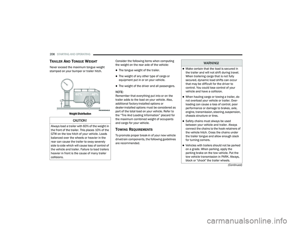
TRAILER AND TONGUE WEIGHT
Never exceed the maximum tongue weight
stamped on your bumper or trailer hitch.
Weight Distribution
Consider the following items when computing
the weight on the rear axle of the vehicle:The tongue weight of the trailer.
The weight of any other type of cargo or
equipment put in or on your vehicle.
The weight of the driver and all passengers.
NOTE:
Remember that everything put into or on the
trailer adds to the load on your vehicle. Also,
additional factory-installed options or
dealer-installed options must be considered as
part of the total load on your vehicle. Refer to
the “Tire And Loading Information” placard for
the maximum combined weight of occupants
and cargo for your vehicle.
TOWING REQUIREMENTS
To promote proper break-in of your new vehicle
drivetrain components, the following guidelines
are recommended.
CAUTION!
Always load a trailer with 60% of the weight in
the front of the trailer. This places 10% of the
GTW on the tow hitch of your vehicle. Loads
balanced over the wheels or heavier in the
rear can cause the trailer to sway severely
side to side which will cause loss of control of
the vehicle and trailer. Failure to load trailers
heavier in front is the cause of many trailer
collisions.
WARNING!
Make certain that the load is secured in
the trailer and will not shift during travel.
When trailering cargo that is not fully
secured, dynamic load shifts can occur
that may be difficult for the driver to
control. You could lose control of your
vehicle and have a collision.
When hauling cargo or towing a trailer, do
not overload your vehicle or trailer. Over -
loading can cause a loss of control, poor
performance or damage to brakes, axle,
engine, transmission, steering, suspension,
chassis structure or tires.
Safety chains must always be used
between your vehicle and trailer. Always
connect the chains to the hook retainers of
the vehicle hitch. Cross the chains under
the trailer tongue and allow enough slack
for turning corners.
Vehicles with trailers should not be parked
on a grade. When parking, apply the
parking brake on the tow vehicle. Put the
tow vehicle transmission in PARK. Always,
block or "chock" the trailer wheels.
20_LD_OM_EN_USC_t.book Page 206
Page 209 of 412
STARTING AND OPERATING207
(Continued)
Perform the maintenance listed in the
“Scheduled Servicing”. Refer to “Scheduled
Servicing” in “Servicing And Maintenance” for
the proper maintenance intervals. When towing
a trailer, never exceed the GAWR or GCWR
ratings.
Towing Requirements — Tires
Do not attempt to tow a trailer while using a
compact spare tire.
Do not drive more than 50 mph (80 km/h) when towing while using a full size spare tire.
Proper tire inflation pressures are essential
to the safe and satisfactory operation of your
vehicle. Refer to “Tires” in “Servicing And
Maintenance” for proper tire inflation proce -
dures.
Check the trailer tires for proper tire inflation
pressures before trailer usage.
Check for signs of tire wear or visible tire
damage before towing a trailer. Refer to
“Tires” in “Servicing And Maintenance” for
the proper inspection procedure.
When replacing tires, refer to “Tires” in
“Servicing And Maintenance” for the proper
tire replacement procedures. Replacing tires
with a higher load carrying capacity will not
increase the vehicle's GVWR and GAWR
limits.
Towing Requirements — Trailer Brakes
Do not interconnect the hydraulic brake
system or vacuum system of your vehicle
with that of the trailer. This could cause inad -
equate braking and possible personal injury.
An electronically actuated trailer brake
controller is required when towing a trailer
with electronically actuated brakes. When
towing a trailer equipped with a hydraulic
surge actuated brake system, an electronic
brake controller is not required.
Trailer brakes are recommended for trailers
over 1,000 lbs (453 kg) and required for
trailers in excess of 2,000 lbs (907 kg).
GCWR must not be exceeded.
Total weight must be distributed between
the tow vehicle and the trailer such that the
following four ratings are not exceeded :
Max loading as defined on the “Tire and
Loading Information” placard.
GTW
GAWR
Tongue weight rating for the trailer
hitch utilized.
CAUTION!
Do not tow a trailer at all during the first
500 miles (805 km) the new vehicle is
driven. The engine, axle or other parts could
be damaged.
WARNING! (Continued)
Then, during the first 500 miles (805 km)
that a trailer is towed, do not drive over
50 mph (80 km/h) and do not make starts
at full throttle. This helps the engine and
other parts of the vehicle wear in at the
heavier loads.
CAUTION! (Continued)
5
20_LD_OM_EN_USC_t.book Page 207
Page 211 of 412
STARTING AND OPERATING209
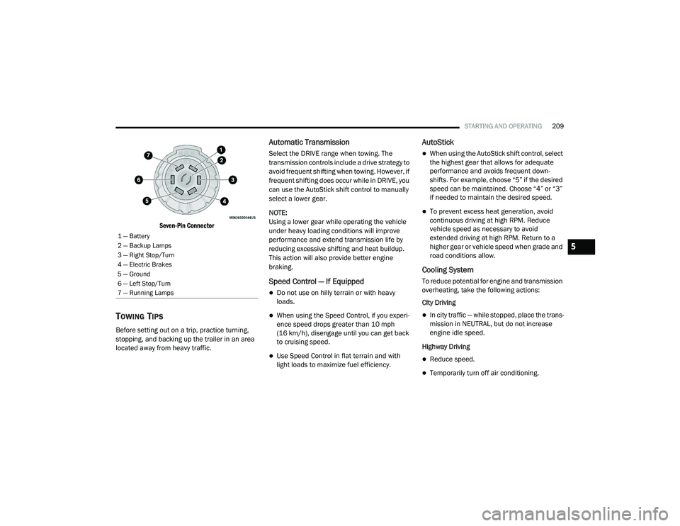
Seven-Pin Connector
TOWING TIPS
Before setting out on a trip, practice turning,
stopping, and backing up the trailer in an area
located away from heavy traffic.
Automatic Transmission
Select the DRIVE range when towing. The
transmission controls include a drive strategy to
avoid frequent shifting when towing. However, if
frequent shifting does occur while in DRIVE, you
can use the AutoStick shift control to manually
select a lower gear.
NOTE:
Using a lower gear while operating the vehicle
under heavy loading conditions will improve
performance and extend transmission life by
reducing excessive shifting and heat buildup.
This action will also provide better engine
braking.
Speed Control — If Equipped
Do not use on hilly terrain or with heavy
loads.
When using the Speed Control, if you experi -
ence speed drops greater than 10 mph
(16 km/h), disengage until you can get back
to cruising speed.
Use Speed Control in flat terrain and with
light loads to maximize fuel efficiency.
AutoStick
When using the AutoStick shift control, select
the highest gear that allows for adequate
performance and avoids frequent down -
shifts. For example, choose “5” if the desired
speed can be maintained. Choose “4” or “3”
if needed to maintain the desired speed.
To prevent excess heat generation, avoid
continuous driving at high RPM. Reduce
vehicle speed as necessary to avoid
extended driving at high RPM. Return to a
higher gear or vehicle speed when grade and
road conditions allow.
Cooling System
To reduce potential for engine and transmission
overheating, take the following actions:
City Driving
In city traffic — while stopped, place the trans -
mission in NEUTRAL, but do not increase
engine idle speed.
Highway Driving
Reduce speed.
Temporarily turn off air conditioning.
1 — Battery
2 — Backup Lamps
3 — Right Stop/Turn
4 — Electric Brakes
5 — Ground
6 — Left Stop/Turn
7 — Running Lamps
5
20_LD_OM_EN_USC_t.book Page 209
Page 213 of 412
STARTING AND OPERATING211
(Continued)
DRIVING THROUGH WATER
Driving through water more than a few inches/
centimeters deep will require extra caution to
ensure safety and prevent damage to your vehicle.
Flowing/Rising Water
Shallow Standing Water
Although your vehicle is capable of driving
through shallow standing water, consider the
following Warnings and Cautions before doing so.
WARNING!
Do not drive on or across a road or path
where water is flowing and/or rising (as in
storm run-off). Flowing water can wear away
the road or path's surface and cause your
vehicle to sink into deeper water.
Furthermore, flowing and/or rising water can
carry your vehicle away swiftly. Failure to
follow this warning may result in injuries that
are serious or fatal to you, your passengers,
and others around you.
WARNING!
Driving through standing water limits your
vehicle’s traction capabilities. Do not
exceed 5 mph (8 km/h) when driving
through standing water.
Driving through standing water limits your
vehicle’s braking capabilities, which
increases stopping distances. Therefore,
after driving through standing water, drive
slowly and lightly press on the brake pedal
several times to dry the brakes.
Failure to follow these warnings may result
in injuries that are serious or fatal to you,
your passengers, and others around you.
CAUTION!
Always check the depth of the standing water
before driving through it. Never drive through
standing water that is deeper than the bottom
of the tire rims mounted on the vehicle.
Determine the condition of the road or the
path that is under water and if there are any
obstacles in the way before driving through
the standing water.
Do not exceed 5 mph (8 km/h) when
driving through standing water. This will
minimize wave effects.
Driving through standing water may cause
damage to your vehicle’s drivetrain compo -
nents. Always inspect your vehicle’s fluids
(i.e., engine oil, transmission, axle, etc.) for
signs of contamination (i.e., fluid that is
milky or foamy in appearance) after driving
through standing water. Do not continue to
operate the vehicle if any fluid appears
contaminated, as this may result in further
damage. Such damage is not covered by
the New Vehicle Limited Warranty.
Getting water inside your vehicle’s engine
can cause it to lock up and stall out, and
cause serious internal damage to the
engine. Such damage is not covered by the
New Vehicle Limited Warranty.
CAUTION! (Continued)
5
20_LD_OM_EN_USC_t.book Page 211
Page 222 of 412
220IN CASE OF EMERGENCY
(Continued)
Front/Rear Side Marker Lamp
The Side Markers use LED lamps that are not
serviceable separately. The Side Markers must
be replaced as an assembly, see an authorized
dealer.
Front Fog Lamp
The Front Fog Lamps use LED sources that are
not serviceable separately. The Front Fog Lamp
must be replaced as an assembly; see an
authorized dealer.
Front Turn Signal Lamps
The Front Park/Turn function is part of the
headlamp assembly and use LED lamps that
are not serviceable separately. The headlamps
must be replaced as an assembly, see an
authorized dealer.
Backup Lamps
The Backup Lamps use LED sources that are
not serviceable separately. The Applique must
be replaced as an assembly; see an authorized
dealer.
License Lamp
The License Lamp uses an LED source that is
not serviceable separately. The License Lamp
must be replaced as an assembly; see an
authorized dealer.
Center High Mounted Stop Lamp (CHMSL)
The CHMSL Lamp uses LED sources that are
not serviceable separately. The CHMSL Lamp
must be replaced as an assembly; see an
authorized dealer.
FUSES
GENERAL INFORMATION
The fuses protect electrical systems against
excessive current.
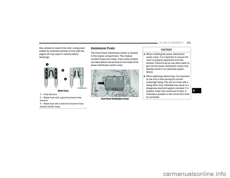
When a device does not work, you must check
the fuse element inside the blade fuse for a
break/melt.
WARNING!
When replacing a blown fuse, always use
an appropriate replacement fuse with the
same amp rating as the original fuse. Never
replace a fuse with another fuse of higher
amp rating. Never replace a blown fuse with
metal wires or any other material. Do not
place a fuse inside a circuit breaker cavity
or vice versa. Failure to use proper fuses
may result in serious personal injury, fire
and/or property damage.
Before replacing a fuse, make sure that the
ignition is off and that all the other services
are switched off and/or disengaged.
If the replaced fuse blows again, contact an
authorized dealer.
If a general protection fuse for safety
systems (air bag system, braking system),
power unit systems (engine system, trans-
mission system) or steering system blows,
contact an authorized dealer.
WARNING! (Continued)
20_LD_OM_EN_USC_t.book Page 220
Page 223 of 412
IN CASE OF EMERGENCY221
Also, please be aware that when using power
outlets for extended periods of time with the
engine off may result in vehicle battery
discharge.
Blade Fuses
UNDERHOOD FUSES
The Front Power Distribution Center is located
in the engine compartment. This module
contains fuses and relays. Fuse cavity location
and descriptions are printed on the inside of the
power distribution center cover.
Front Power Distribution Center
1 — Fuse Element
2 — Blade Fuse with a good/functional fuse
element.
3 — Blade fuse with a bad/not functional fuse
element (blown fuse).
CAUTION!
When installing the power distribution
center cover, it is important to ensure the
cover is properly positioned and fully
latched. Failure to do so may allow water to
get into the power distribution center and
possibly result in an electrical system
failure.
When replacing a blown fuse, it is important
to use only a fuse having the correct
amperage rating. The use of a fuse with a
rating other than indicated may result in a
dangerous electrical system overload. If a
properly rated fuse continues to blow, it
indicates a problem in the circuit that must
be corrected.
6
20_LD_OM_EN_USC_t.book Page 221