fuel pressure DODGE CHARGER 2020 Owners Manual
[x] Cancel search | Manufacturer: DODGE, Model Year: 2020, Model line: CHARGER, Model: DODGE CHARGER 2020Pages: 412, PDF Size: 18.96 MB
Page 6 of 412
4
SAFETY
SAFETY FEATURES ............................................ 106
Anti-Lock Brake System (ABS) ................. 106
Electronic Brake Control (EBC) System ...107
AUXILIARY DRIVING SYSTEMS ........................ 113
Blind Spot Monitoring (BSM) —
If Equipped .................................................113 Forward Collision Warning (FCW) With
Mitigation Operation ..................................118
Tire Pressure Monitoring System (TPMS) ... 120
OCCUPANT RESTRAINT SYSTEMS .................. 125
Occupant Restraint Systems Features ....125
Important Safety Precautions ...................125Seat Belt Systems ..................................... 126Supplemental Restraint Systems (SRS) ...134Child Restraints..........................................143Transporting Pets ......................................155
SAFETY TIPS ...................................................... 155
Transporting Passengers ..........................155
Exhaust Gas ...............................................155Safety Checks You Should Make
Inside The Vehicle ..................................... 156 Periodic Safety Checks You Should
Make Outside The Vehicle ........................ 157
STARTING AND OPERATING
STARTING THE ENGINE ....................................159
Automatic Transmission ........................... 159
Normal Starting ......................................... 159
Keyless Enter-N-Go — Ignition ................... 162
Cold Weather Operation (Below –22°F
Or −30°C) ................................................. 162 If Engine Fails To Start .............................. 162
After Starting .............................................. 162
ENGINE BLOCK HEATER — IF EQUIPPED .......162
ENGINE BREAK-IN RECOMMENDATIONS —
3.6L & 5.7L ........................................................ 163
ENGINE BREAK-IN RECOMMENDATIONS —
6.2L & 6.4L ......................................................... 163
PARKING BRAKE ................................................ 164
AUTOMATIC TRANSMISSION ............................ 165 Ignition Park Interlock ............................... 166Brake/Transmission Shift Interlock
System ....................................................... 167 Eight-Speed Automatic Transmission ...... 167
SPORT MODE — WITHOUT PERFORMANCE
CONTROL............................................................. 174
FUEL SAVER TECHNOLOGY 5.7L AND
6.4L ONLY — IF EQUIPPED ................................174
ELECTRIC POWER STEERING ........................... 174 SPEED CONTROL — IF EQUIPPED.................... 175
To Activate.................................................. 175
To Set A Desired Speed ........................... 176
To Vary The Speed Setting ....................... 176To Accelerate For Passing ........................ 177
To Resume Speed .................................... 177To Deactivate ............................................ 177
ADAPTIVE CRUISE CONTROL (ACC) —
IF EQUIPPED ...................................................... 177
Adaptive Cruise Control (ACC) Operation ... 179
Activating Adaptive Cruise Control (ACC) ... 179
To Activate/Deactivate.............................. 180
To Set A Desired ACC Speed..................... 180
To Cancel ................................................... 181
To Turn Off ................................................. 181To Resume ................................................. 181To Vary The ACC Speed ............................. 181
Setting The Following Distance In ACC .... 183
Overtake Aid............................................... 184
ACC Operation At Stop............................... 184Adaptive Cruise Control (ACC) Menu ........ 185
Display Warnings And Maintenance ........ 185
Precautions While Driving With ACC......... 187
General Information .................................. 189
Normal (Fixed Speed) Cruise
Control Mode ............................................. 189
20_LD_OM_EN_USC_t.book Page 4
Page 8 of 412
6
ENGINE COMPARTMENT .................................. 266 3.6L Engine ...............................................2665.7L Engine ...............................................2676.2L Supercharged Engine ......................268
6.4L Engine ...............................................269Checking Oil Level — 3.6L And 5.7L
Engine.........................................................270 Checking Oil Level — 6.2L Supercharged
Engine And 6.4L Engine ...........................270 Adding Washer Fluid..................................270Maintenance-Free Battery .......................271
Pressure Washing ......................................271
DEALER SERVICE .............................................. 272
Engine Oil .................................................. 272Engine Oil Filter ..........................................274Engine Air Cleaner Filter ...........................275
Air Conditioner Maintenance ...................275Accessory Drive Belt Inspection................276Body Lubrication ........................................277
Windshield Wiper Blades ..........................278
Exhaust System .........................................279
Cooling System .........................................280
Brake System ............................................284
Automatic Transmission ............................285
Rear Axle ....................................................286
RAISING THE VEHICLE ...................................... 286 TIRES....................................................................286
Tire Safety Information ............................. 286Tires — General Information .................... 293
Tire Types ................................................... 298
Spare Tires — If Equipped ......................... 298
Wheel And Wheel Trim Care .................... 300
Tire Chains And Traction Devices —
Non-SRT ..................................................... 301 Tire Chains And Traction Devices — SRT.. 302
Tire Rotation Recommendations —
Non-SRT ..................................................... 302
Tire Rotation Recommendations — SRT .... 303
DEPARTMENT OF TRANSPORTATION UNIFORM
TIRE QUALITY GRADES .....................................303
Treadwear .................................................. 303
Traction Grades ......................................... 303
Temperature Grades ................................. 304
VEHICLE STORAGE .............................................304
BODYWORK ........................................................ 304
Protection From Atmospheric Agents....... 304
Body And Underbody Maintenance .......... 305Preserving The Bodywork .......................... 305
INTERIORS ......................................................... 306
Seats And Fabric Parts .............................. 306
Plastic And Coated Parts ........................... 306
Leather Parts ............................................. 307
Glass Surfaces .......................................... 307
TECHNICAL SPECIFICATIONS
IDENTIFICATION DATA ...................................... 308Vehicle Identification Number .................. 308
BRAKE SYSTEM ................................................ 308
WHEEL AND TIRE TORQUE
SPECIFICATIONS ................................................ 308
Torque Specifications................................ 308
FUEL REQUIREMENTS ...................................... 309
3.6L Engine ................................................ 309
5.7L Engine ................................................ 310
6.2L And 6.4L Engine................................ 310
Reformulated Gasoline ............................ 310Materials Added To Fuel ........................... 310
Gasoline/Oxygenate Blends ..................... 311
Do Not Use E-85 In Non-Flex Fuel
Vehicles ...................................................... 311 CNG And LP Fuel System Modifications .. 312MMT In Gasoline........................................ 312
Fuel System Cautions................................ 312
Carbon Monoxide Warnings...................... 312
FLUID CAPACITIES — NON-SRT ....................... 313
FLUID CAPACITIES — SRT ................................ 314
FLUIDS AND LUBRICANTS — NON-SRT .......... 315 Engine ........................................................ 315
Chassis ....................................................... 317
FLUIDS AND LUBRICANTS — SRT ................... 318
Engine ........................................................ 318
Chassis ....................................................... 320
20_LD_OM_EN_USC_t.book Page 6
Page 85 of 412
GETTING TO KNOW YOUR INSTRUMENT PANEL83
4. Fuel Gauge
The pointer shows the level of fuel in the
fuel tank when the Keyless Push Button
Ignition is in the ON/RUN position.
The fuel pump symbol points
to the side of the vehicle where
the fuel door is located.
Refer to “Refueling The Vehicle” in “Starting
And Operating” for further information.
5. Temperature Gauge
The temperature gauge shows engine
coolant temperature. Any reading within
the normal range indicates that the
engine cooling system is operating satis -
factorily.
The gauge pointer will likely indicate a
higher temperature when driving in hot
weather, up mountain grades, or when
towing a trailer. It should not be allowed
to exceed the upper limits of the normal
operating range.
NOTE:
The hard telltales will illuminate for a bulb check
when the ignition is first cycled.
WARNING!
A hot engine cooling system is dangerous.
You or others could be badly burned by steam
or boiling coolant. You may want to call an
authorized dealer for service if your vehicle
overheats. If you decide to look under the
hood yourself, see “Servicing And
Maintenance.” Follow the warnings under the
Cooling System Pressure Cap paragraph.
CAUTION!
Driving with a hot engine cooling system
could damage your vehicle. If the
temperature gauge reads “H,” pull over and
stop the vehicle. Idle the vehicle with the air
conditioner turned off until the pointer drops
back into the normal range. If the pointer
remains on the “H,” turn the engine off
immediately and call an authorized dealer for
service.
3
20_LD_OM_EN_USC_t.book Page 83
Page 87 of 412
GETTING TO KNOW YOUR INSTRUMENT PANEL85
4. Fuel Gauge
The pointer shows the level of fuel in the
fuel tank when the Keyless Push Button
Ignition is in the ON/RUN position.
The fuel pump symbol points
to the side of the vehicle where
the fuel door is located.
Refer to “Refueling The Vehicle” in “Starting
And Operating” for further information.
5. Temperature Gauge
The temperature gauge shows engine
coolant temperature. Any reading within
the normal range indicates that the
engine cooling system is operating satis -
factorily.
The gauge pointer will likely indicate a
higher temperature when driving in hot
weather, up mountain grades, or when
towing a trailer. It should not be allowed
to exceed the upper limits of the normal
operating range. NOTE:
The hard telltales will illuminate for a bulb check
when the ignition is first cycled.
INSTRUMENT CLUSTER DISPLAY
Your vehicle will be equipped with an
instrument cluster display, which offers useful
information to the driver. With the ignition in the
OFF mode, opening/closing of a door will
activate the display for viewing, and display the
total miles, or kilometers, in the odometer. Your
instrument cluster display is designed to display
important information about your vehicle’s
systems and features. Using a driver interactive
display located on the instrument panel, your
instrument cluster display can show you how
systems are working and give you warnings
when they are not. The steering wheel mounted
controls allow you to scroll through the main
menus and submenus. You can access the
specific information you want and make
selections and adjustments.
WARNING!
A hot engine cooling system is dangerous.
You or others could be badly burned by steam
or boiling coolant. You may want to call an
authorized dealer for service if your vehicle
overheats. If you decide to look under the
hood yourself, see “Servicing And
Maintenance.” Follow the warnings under the
Cooling System Pressure Cap paragraph.
CAUTION!
Driving with a hot engine cooling system
could damage your vehicle. If the
temperature gauge reads greater than 230°F
(110°C) pull over and stop the vehicle. Idle
the vehicle with the air conditioner turned off
until the pointer drops back into the normal
range. If the pointer remains above 230°F
(110°C), turn the engine off immediately and
call an authorized dealer for service.
3
20_LD_OM_EN_USC_t.book Page 85
Page 90 of 412
88GETTING TO KNOW YOUR INSTRUMENT PANEL
Secondary Method Of Resetting Engine Oil Life
1. Without pressing the brake pedal, push the
ENGINE START/STOP button and place the
ignition to the ON/RUN position (do not
start the engine).
2. Fully press the accelerator pedal, slowly, three times within ten seconds.
3. Without pushing the brake pedal, push the ENGINE START/STOP button once to return
the ignition to the OFF/LOCK position.
NOTE:
If the indicator message illuminates when you
start the vehicle, the oil change indicator
system did not reset. If necessary, repeat this
procedure.
PERFORMANCE SHIFT INDICATOR (PSI)
— I
F EQUIPPED
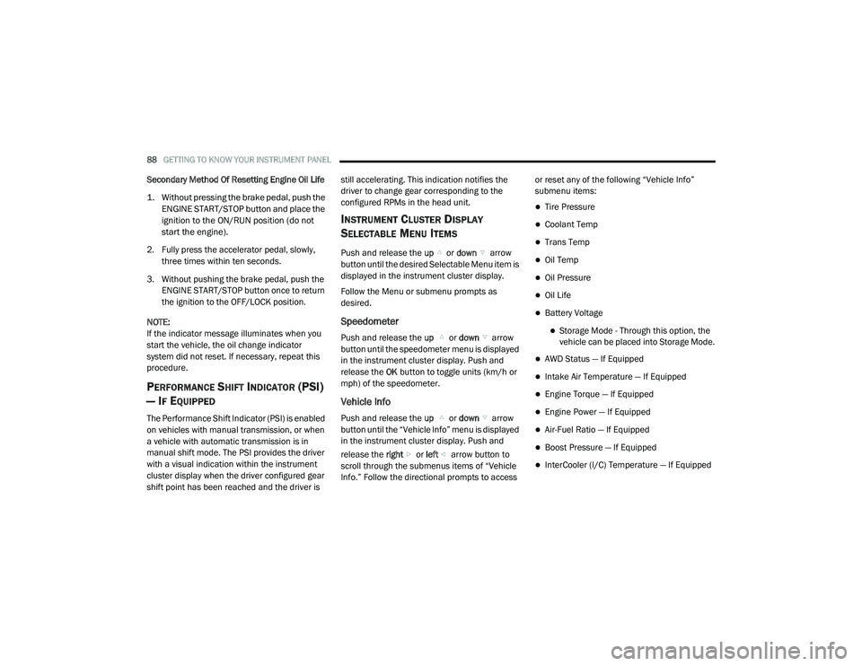
The Performance Shift Indicator (PSI) is enabled
on vehicles with manual transmission, or when
a vehicle with automatic transmission is in
manual shift mode. The PSI provides the driver
with a visual indication within the instrument
cluster display when the driver configured gear
shift point has been reached and the driver is still accelerating. This indication notifies the
driver to change gear corresponding to the
configured RPMs in the head unit.
INSTRUMENT CLUSTER DISPLAY
S
ELECTABLE MENU ITEMS
Push and release the up or down arrow
button until the desired Selectable Menu item is
displayed in the instrument cluster display.
Follow the Menu or submenu prompts as
desired.
Speedometer
Push and release the up or down arrow
button until the speedometer menu is displayed
in the instrument cluster display. Push and
release the OK button to toggle units (km/h or
mph) of the speedometer.
Vehicle Info
Push and release the up or down arrow
button until the “Vehicle Info” menu is displayed
in the instrument cluster display. Push and
release the right or left arrow button to
scroll through the submenus items of “Vehicle
Info.” Follow the directional prompts to access or reset any of the following “Vehicle Info”
submenu items:
Tire Pressure
Coolant Temp
Trans Temp
Oil Temp
Oil Pressure
Oil Life
Battery Voltage
Storage Mode - Through this option, the
vehicle can be placed into Storage Mode.
AWD Status — If Equipped
Intake Air Temperature — If Equipped
Engine Torque — If Equipped
Engine Power — If Equipped
Air-Fuel Ratio — If Equipped
Boost Pressure — If Equipped
InterCooler (I/C) Temperature — If Equipped
20_LD_OM_EN_USC_t.book Page 88
Page 101 of 412
GETTING TO KNOW YOUR INSTRUMENT PANEL99
The “ESC OFF Indicator Light” and the “ESC
Indicator Light” come on momentarily each
time the ignition is placed in the ON/RUN or
ACC/ON/RUN position.
The ESC system will make buzzing or clicking
sounds when it is active. This is normal; the
sounds will stop when ESC becomes inactive.
This light will come on when the vehicle is in
an ESC event.
Electronic Stability Control (ESC) OFF
Warning Light — If Equipped
This warning light indicates the
Electronic Stability Control (ESC) is
off.
Each time the ignition is turned to ON/RUN or
ACC/ON/RUN, the ESC system will be on, even
if it was turned off previously.
The ESC OFF indicator will be lit any time the
Traction Mode is set to Sport, Track or Full OFF
in Drive Modes.
Low Washer Fluid Warning Light —
If Equipped
This warning light will illuminate when
the windshield washer fluid is low.
Refer to “Engine Compartment” in
“Servicing And Maintenance” for further
information.
Tire Pressure Monitoring System (TPMS)
Warning Light
The warning light switches on and a
message is displayed to indicate that
the tire pressure is lower than the
recommended value and/or that slow
pressure loss is occurring. In these cases,
optimal tire duration and fuel consumption may
not be guaranteed.
Should one or more tires be in the condition
mentioned above, the display will show the
indications corresponding to each tire. Each tire, including the spare (if provided),
should be checked monthly when cold and
inflated to the inflation pressure recommended
by the vehicle manufacturer on the vehicle
placard or tire inflation pressure label. If your
vehicle has tires of a different size than the size
indicated on the vehicle placard or tire inflation
pressure label, you should determine the
proper tire inflation pressure for those tires.
CAUTION!
Do not continue driving with one or more flat
tires as handling may be compromised. Stop
the vehicle, avoiding sharp braking and
steering. If a tire puncture occurs, repair
immediately using the dedicated tire repair
kit and contact an authorized dealer as soon
as possible.
3
20_LD_OM_EN_USC_t.book Page 99
Page 102 of 412
100GETTING TO KNOW YOUR INSTRUMENT PANEL
As an added safety feature, your vehicle has
been equipped with a Tire Pressure Monitoring
System (TPMS) that illuminates a low tire
pressure telltale when one or more of your tires is
significantly under-inflated. Accordingly, when
the low tire pressure telltale illuminates, you
should stop and check your tires as soon as
possible, and inflate them to the proper pressure.
Driving on a significantly under-inflated tire
causes the tire to overheat and can lead to tire
failure. Under-inflation also reduces fuel
efficiency and tire tread life, and may affect the
vehicle’s handling and stopping ability.
Please note that the TPMS is not a substitute for
proper tire maintenance, and it is the driver’s
responsibility to maintain correct tire pressure,
even if under-inflation has not reached the level
to trigger illumination of the TPMS low tire
pressure telltale. Your vehicle has also been equipped with a
TPMS malfunction indicator to indicate when
the system is not operating properly. The TPMS
malfunction indicator is combined with the low
tire pressure telltale. When the system detects
a malfunction, the telltale will flash for
approximately one minute and then remain
continuously illuminated. This sequence will
continue upon subsequent vehicle start-ups as
long as the malfunction exists. When the
malfunction indicator is illuminated, the system
may not be able to detect or signal low tire
pressure as intended. TPMS malfunctions may
occur for a variety of reasons, including the
installation of replacement or alternate tires or
wheels on the vehicle that prevent the TPMS
from functioning properly. Always check the
TPMS malfunction telltale after replacing one or
more tires or wheels on your vehicle to ensure
that the replacement or alternate tires and
wheels allow the TPMS to continue to function
properly.CAUTION!
The TPMS has been optimized for the original
equipment tires and wheels. TPMS pressures
and warning have been established for the
tire size equipped on your vehicle.
Undesirable system operation or sensor
damage may result when using replacement
equipment that is not of the same size, type,
and/or style. Aftermarket wheels can cause
sensor damage. Using aftermarket tire
sealants may cause the Tire Pressure
Monitoring System (TPMS) sensor to become
inoperable. After using an aftermarket tire
sealant it is recommended that you take your
vehicle to an authorized dealer to have your
sensor function checked.
20_LD_OM_EN_USC_t.book Page 100
Page 124 of 412
122SAFETY
NOTE:
The TPMS is not intended to replace normal
tire care and maintenance or to provide
warning of a tire failure or condition.
The TPMS should not be used as a tire pres -
sure gauge while adjusting your tire pressure.
Driving on a significantly under-inflated tire
causes the tire to overheat and can lead to
tire failure. Under-inflation also reduces fuel
efficiency and tire tread life, and may affect
the vehicle’s handling and stopping ability.
The TPMS is not a substitute for proper tire
maintenance, and it is the driver’s responsi -
bility to maintain correct tire pressure using
an accurate tire pressure gauge, even if
under-inflation has not reached the level to
trigger illumination of the TPMS Warning
Light.
Seasonal temperature changes will affect
tire pressure, and the TPMS will monitor the
actual tire pressure in the tire.
Premium System
The Tire Pressure Monitoring System (TPMS)
uses wireless technology with wheel rim
mounted electronic sensors to monitor tire
pressure levels. Sensors, mounted to each
wheel as part of the valve stem, transmit tire
pressure readings to the receiver module.
NOTE:
It is particularly important for you to check the
tire pressure in all of the tires on your vehicle
monthly and to maintain the proper pressure.
The TPMS consists of the following
components:
Receiver module
Four Tire Pressure Monitoring sensors
Various Tire Pressure Monitoring System
messages, which display in the instrument
cluster
Tire Pressure Monitoring System Warning
Light
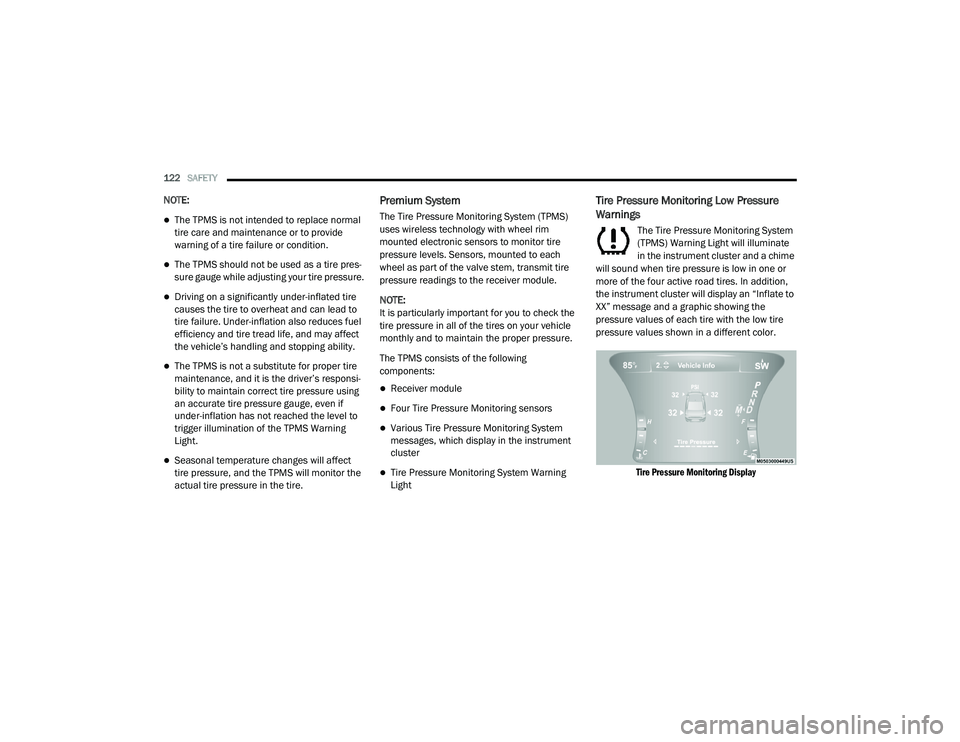
Tire Pressure Monitoring Low Pressure
Warnings
The Tire Pressure Monitoring System
(TPMS) Warning Light will illuminate
in the instrument cluster and a chime
will sound when tire pressure is low in one or
more of the four active road tires. In addition,
the instrument cluster will display an “Inflate to
XX” message and a graphic showing the
pressure values of each tire with the low tire
pressure values shown in a different color.
Tire Pressure Monitoring Display
20_LD_OM_EN_USC_t.book Page 122
Page 228 of 412
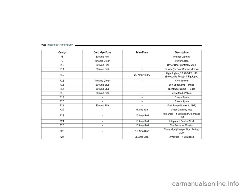
226IN CASE OF EMERGENCY
F8 30 Amp Pink –Interior Lighting
F9 40 Amp Green –Power Locks
F10 30 Amp Pink –Driver Door Control Module
F11 30 Amp Pink –Passenger Door Control Module
F12 –20 Amp YellowCigar Lighter/IP APO/RR USB
(Selectable Fuse)– If Equipped
F15 40 Amp Green –HVAC Blower
F16 20 Amp Blue –Left Spot Lamp – Police
F17 20 Amp Blue –Right Spot Lamp – Police
F18 30 Amp Pink –VISM Mod (Police)
F19 ––Fuse – Spare
F20 ––Fuse – Spare
F21 30 Amp Pink –Fuel Pump (Non 6.2L ADR)
F22 –5 Amp Tan Cyber Gateway Mod
F23 –10 Amp RedFuel Door – If Equipped/Diagnostic
Port
F24 –10 Amp RedIntegrated Center Stack
F25 –10 Amp Red Tire Pressure Monitor
F26 –15 Amp BlueTrans Mod (Charger Non- Police/
300)
F27 –25 Amp Clear Amplifier – If Equipped
CavityCartridge Fuse Mini-FuseDescription
20_LD_OM_EN_USC_t.book Page 226
Page 257 of 412

SERVICING AND MAINTENANCE255
An authorized dealer will reset the oil change
indicator message after completing the
scheduled oil change. If a scheduled oil change
is performed by someone other than an
authorized dealer, the message can be reset by
referring to the steps described under
“Instrument Cluster Display” in “Getting To
Know Your Instrument Panel” for further
information.
At Each Stop For Fuel
Check the engine oil level. Refer to “Engine
Compartment” in this chapter for further
information.
Check the windshield washer solvent and
add if required. Once A Month
Check tire pressure and look for unusual
wear or damage.
Inspect the battery, and clean and tighten the
terminals as required.
Check the fluid levels of the coolant reservoir,
brake master cylinder, and power steering
(6.2L only), and add as needed.
Check all lights and other electrical items for
correct operation.
At Each Oil Change
Change the engine oil filter.
Inspect the brake hoses and lines.
Inspect the CV/Universal joints.
CAUTION!
Failure to perform the required maintenance
items may result in damage to the vehicle.
7
20_LD_OM_EN_USC_t.book Page 255