suspension DODGE CHARGER 2021 Owners Manual
[x] Cancel search | Manufacturer: DODGE, Model Year: 2021, Model line: CHARGER, Model: DODGE CHARGER 2021Pages: 320, PDF Size: 20.61 MB
Page 99 of 320
STARTING AND OPERATING97
(Continued)
(Continued)
NOTE:
If the ACC sensor detects a vehicle ahead, ACC
will apply limited braking or acceleration (not to
exceed the original set speed) automatically to
maintain a preset following distance, while
matching the speed of the vehicle ahead.
Any chassis/suspension or tire size modifica -
tions to the vehicle will affect the performance
of the Adaptive Cruise Control and Forward Colli -
sion Warning systems.
Fixed Speed Cruise Control (ACC not enabled)
will not detect vehicles directly ahead of you.
Always be aware of the feature selected
Ú page 305.
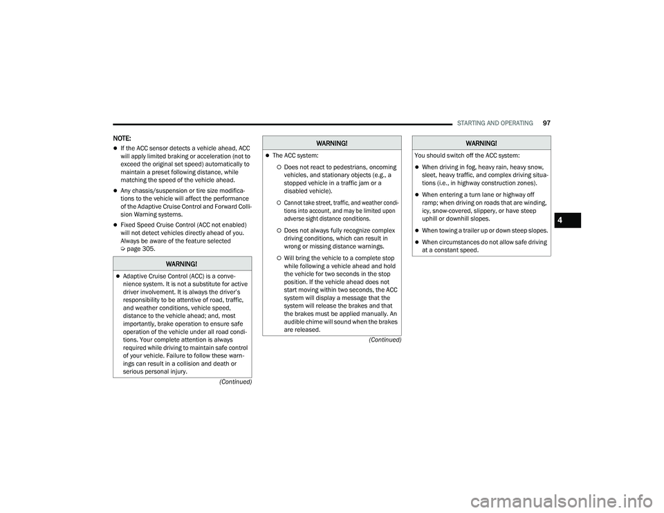
WARNING!
Adaptive Cruise Control (ACC) is a conve -
nience system. It is not a substitute for active
driver involvement. It is always the driver’s
responsibility to be attentive of road, traffic,
and weather conditions, vehicle speed,
distance to the vehicle ahead; and, most
importantly, brake operation to ensure safe
operation of the vehicle under all road condi -
tions. Your complete attention is always
required while driving to maintain safe control
of your vehicle. Failure to follow these warn -
ings can result in a collision and death or
serious personal injury.
The ACC system:
Does not react to pedestrians, oncoming
vehicles, and stationary objects (e.g., a
stopped vehicle in a traffic jam or a
disabled vehicle).
Cannot take street, traffic, and weather condi -
tions into account, and may be limited upon
adverse sight distance conditions.
Does not always fully recognize complex
driving conditions, which can result in
wrong or missing distance warnings.
Will bring the vehicle to a complete stop
while following a vehicle ahead and hold
the vehicle for two seconds in the stop
position. If the vehicle ahead does not
start moving within two seconds, the ACC
system will display a message that the
system will release the brakes and that
the brakes must be applied manually. An
audible chime will sound when the brakes
are released.
WARNING!
You should switch off the ACC system:
When driving in fog, heavy rain, heavy snow,
sleet, heavy traffic, and complex driving situa -
tions (i.e., in highway construction zones).
When entering a turn lane or highway off
ramp; when driving on roads that are winding,
icy, snow-covered, slippery, or have steep
uphill or downhill slopes.
When towing a trailer up or down steep slopes.
When circumstances do not allow safe driving
at a constant speed.
WARNING!
4
21_LD_OM_EN_USC_t.book Page 97
Page 117 of 320
STARTING AND OPERATING115
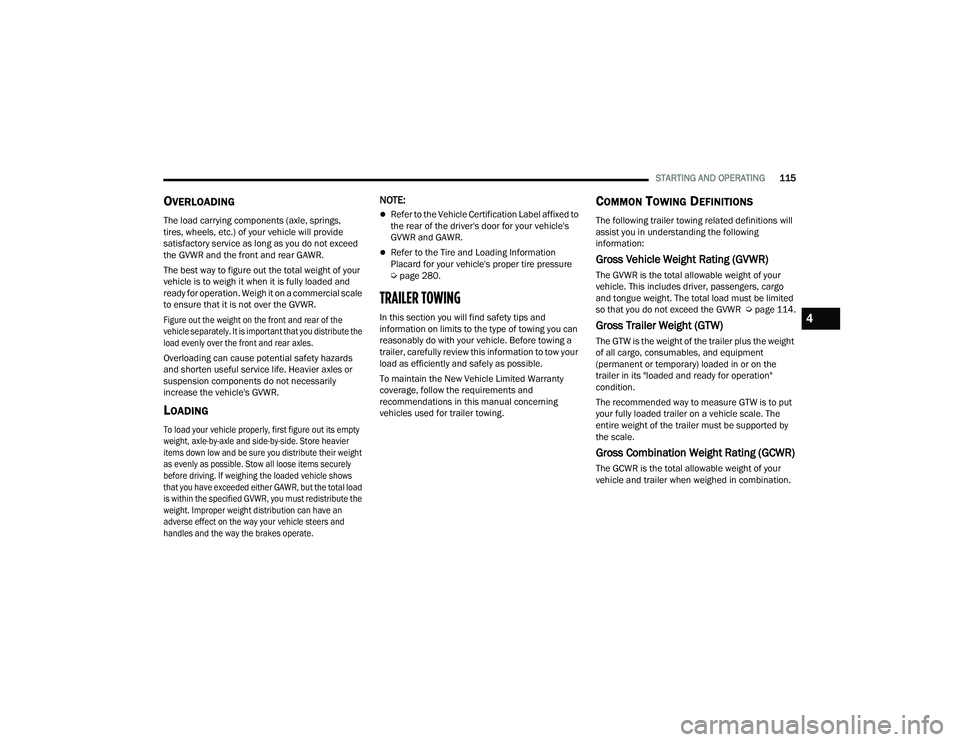
OVERLOADING
The load carrying components (axle, springs,
tires, wheels, etc.) of your vehicle will provide
satisfactory service as long as you do not exceed
the GVWR and the front and rear GAWR.
The best way to figure out the total weight of your
vehicle is to weigh it when it is fully loaded and
ready for operation. Weigh it on a commercial scale
to ensure that it is not over the GVWR.
Figure out the weight on the front and rear of the
vehicle separately. It is important that you distribute the
load evenly over the front and rear axles.
Overloading can cause potential safety hazards
and shorten useful service life. Heavier axles or
suspension components do not necessarily
increase the vehicle's GVWR.
LOADING
To load your vehicle properly, first figure out its empty
weight, axle-by-axle and side-by-side. Store heavier
items down low and be sure you distribute their weight
as evenly as possible. Stow all loose items securely
before driving. If weighing the loaded vehicle shows
that you have exceeded either GAWR, but the total load
is within the specified GVWR, you must redistribute the
weight. Improper weight distribution can have an
adverse effect on the way your vehicle steers and
handles and the way the brakes operate.
NOTE:
Refer to the Vehicle Certification Label affixed to
the rear of the driver's door for your vehicle's
GVWR and GAWR.
Refer to the Tire and Loading Information
Placard for your vehicle's proper tire pressure
Úpage 280.
TRAILER TOWING
In this section you will find safety tips and
information on limits to the type of towing you can
reasonably do with your vehicle. Before towing a
trailer, carefully review this information to tow your
load as efficiently and safely as possible.
To maintain the New Vehicle Limited Warranty
coverage, follow the requirements and
recommendations in this manual concerning
vehicles used for trailer towing.
COMMON TOWING DEFINITIONS
The following trailer towing related definitions will
assist you in understanding the following
information:
Gross Vehicle Weight Rating (GVWR)
The GVWR is the total allowable weight of your
vehicle. This includes driver, passengers, cargo
and tongue weight. The total load must be limited
so that you do not exceed the GVWR Ú page 114.
Gross Trailer Weight (GTW)
The GTW is the weight of the trailer plus the weight
of all cargo, consumables, and equipment
(permanent or temporary) loaded in or on the
trailer in its "loaded and ready for operation"
condition.
The recommended way to measure GTW is to put
your fully loaded trailer on a vehicle scale. The
entire weight of the trailer must be supported by
the scale.
Gross Combination Weight Rating (GCWR)
The GCWR is the total allowable weight of your
vehicle and trailer when weighed in combination.
4
21_LD_OM_EN_USC_t.book Page 115
Page 120 of 320
118STARTING AND OPERATING
(Continued)
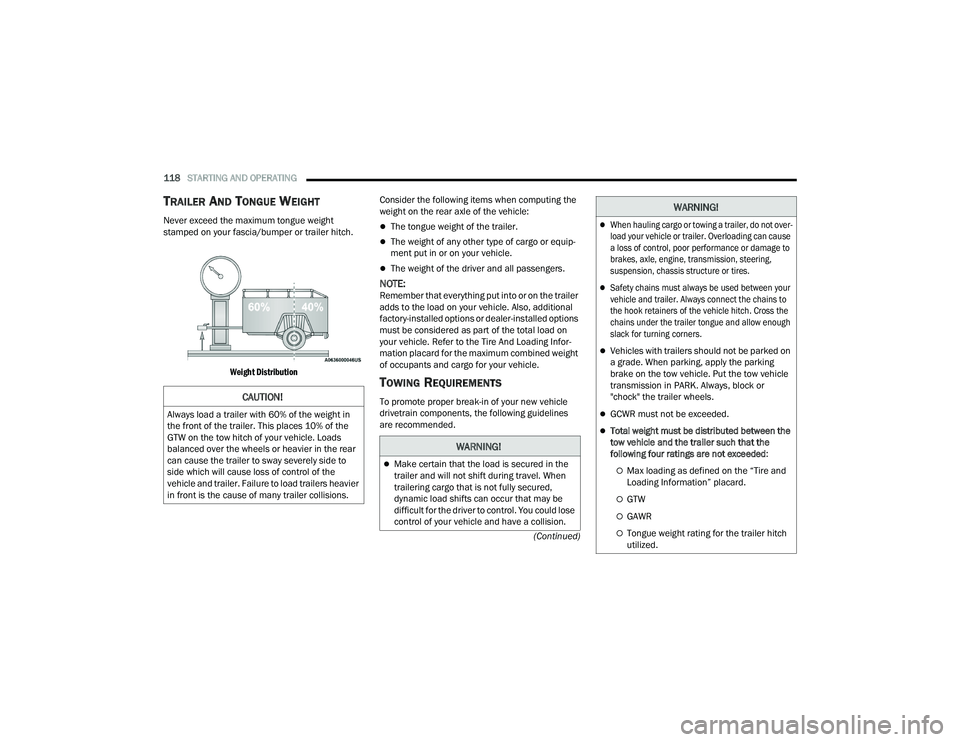
TRAILER AND TONGUE WEIGHT
Never exceed the maximum tongue weight
stamped on your fascia/bumper or trailer hitch.
Weight Distribution
Consider the following items when computing the
weight on the rear axle of the vehicle:The tongue weight of the trailer.
The weight of any other type of cargo or equip
-
ment put in or on your vehicle.
The weight of the driver and all passengers.
NOTE:Remember that everything put into or on the trailer
adds to the load on your vehicle. Also, additional
factory-installed options or dealer-installed options
must be considered as part of the total load on
your vehicle. Refer to the Tire And Loading Infor -
mation placard for the maximum combined weight
of occupants and cargo for your vehicle.
TOWING REQUIREMENTS
To promote proper break-in of your new vehicle
drivetrain components, the following guidelines
are recommended.CAUTION!
Always load a trailer with 60% of the weight in
the front of the trailer. This places 10% of the
GTW on the tow hitch of your vehicle. Loads
balanced over the wheels or heavier in the rear
can cause the trailer to sway severely side to
side which will cause loss of control of the
vehicle and trailer. Failure to load trailers heavier
in front is the cause of many trailer collisions.
WARNING!
Make certain that the load is secured in the
trailer and will not shift during travel. When
trailering cargo that is not fully secured,
dynamic load shifts can occur that may be
difficult for the driver to control. You could lose
control of your vehicle and have a collision.
When hauling cargo or towing a trailer, do not over -
load your vehicle or trailer. Overloading can cause
a loss of control, poor performance or damage to
brakes, axle, engine, transmission, steering,
suspension, chassis structure or tires.
Safety chains must always be used between your
vehicle and trailer. Always connect the chains to
the hook retainers of the vehicle hitch. Cross the
chains under the trailer tongue and allow enough
slack for turning corners.
Vehicles with trailers should not be parked on
a grade. When parking, apply the parking
brake on the tow vehicle. Put the tow vehicle
transmission in PARK. Always, block or
"chock" the trailer wheels.
GCWR must not be exceeded.
Total weight must be distributed between the
tow vehicle and the trailer such that the
following four ratings are not exceeded :
Max loading as defined on the “Tire and
Loading Information” placard.
GTW
GAWR
Tongue weight rating for the trailer hitch
utilized.
WARNING!
21_LD_OM_EN_USC_t.book Page 118
Page 177 of 320
MULTIMEDIA175
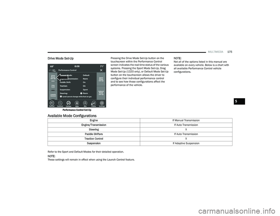
Drive Mode Set-Up
Performance Control Set-Up
Pressing the Drive Mode Set-Up button on the
touchscreen within the Performance Control
screen indicates the real-time status of the various
systems. Pressing the Sport Mode Set-Up, Drag
Mode Set-Up (1320 only), or Default Mode Set-Up
button on the touchscreen allows the driver to
configure their individual performance control
and to see how those configurations affect the
performance of the vehicle.
NOTE:Not all of the options listed in this manual are
available on every vehicle. Below is a chart with
all available Performance Control vehicle
configurations.
Available Mode Configurations
Refer to the Sport and Default Modes for their detailed operation.
NOTE:These settings will remain in effect when using the Launch Control feature.
Engine
If Manual Transmission
Engine/Transmission If Auto Transmission
Steering X
Paddle Shifters If Auto Transmission
Traction Control X
Suspension If Adaptive Suspension
5
21_LD_OM_EN_USC_t.book Page 175
Page 184 of 320
182SAFETY
(Continued)
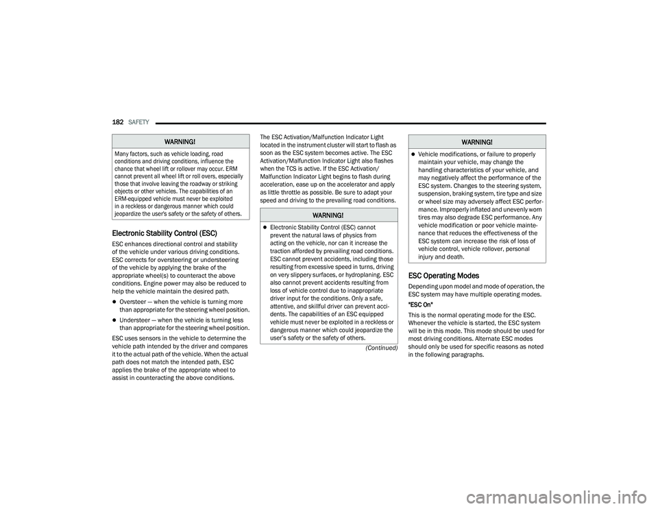
Electronic Stability Control (ESC)
ESC enhances directional control and stability
of the vehicle under various driving conditions.
ESC corrects for oversteering or understeering
of the vehicle by applying the brake of the
appropriate wheel(s) to counteract the above
conditions. Engine power may also be reduced to
help the vehicle maintain the desired path.
Oversteer — when the vehicle is turning more
than appropriate for the steering wheel position.
Understeer — when the vehicle is turning less
than appropriate for the steering wheel position.
ESC uses sensors in the vehicle to determine the
vehicle path intended by the driver and compares
it to the actual path of the vehicle. When the actual
path does not match the intended path, ESC
applies the brake of the appropriate wheel to
assist in counteracting the above conditions.
The ESC Activation/Malfunction Indicator Light
located in the instrument cluster will start to flash as
soon as the ESC system becomes active. The ESC
Activation/Malfunction Indicator Light also flashes
when the TCS is active. If the ESC Activation/
Malfunction Indicator Light begins to flash during
acceleration, ease up on the accelerator and apply
as little throttle as possible. Be sure to adapt your
speed and driving to the prevailing road conditions.
ESC Operating Modes
Depending upon model and mode of operation, the
ESC system may have multiple operating modes.
"ESC On"
This is the normal operating mode for the ESC.
Whenever the vehicle is started, the ESC system
will be in this mode. This mode should be used for
most driving conditions. Alternate ESC modes
should only be used for specific reasons as noted
in the following paragraphs.
WARNING!
Many factors, such as vehicle loading, road
conditions and driving conditions, influence the
chance that wheel lift or rollover may occur. ERM
cannot prevent all wheel lift or roll overs, especially
those that involve leaving the roadway or striking
objects or other vehicles. The capabilities of an
ERM-equipped vehicle must never be exploited
in a reckless or dangerous manner which could
jeopardize the user's safety or the safety of others.
WARNING!
Electronic Stability Control (ESC) cannot
prevent the natural laws of physics from
acting on the vehicle, nor can it increase the
traction afforded by prevailing road conditions.
ESC cannot prevent accidents, including those
resulting from excessive speed in turns, driving
on very slippery surfaces, or hydroplaning. ESC
also cannot prevent accidents resulting from
loss of vehicle control due to inappropriate
driver input for the conditions. Only a safe,
attentive, and skillful driver can prevent acci
-
dents. The capabilities of an ESC equipped
vehicle must never be exploited in a reckless or
dangerous manner which could jeopardize the
user’s safety or the safety of others.
Vehicle modifications, or failure to properly
maintain your vehicle, may change the
handling characteristics of your vehicle, and
may negatively affect the performance of the
ESC system. Changes to the steering system,
suspension, braking system, tire type and size
or wheel size may adversely affect ESC perfor -
mance. Improperly inflated and unevenly worn
tires may also degrade ESC performance. Any
vehicle modification or poor vehicle mainte -
nance that reduces the effectiveness of the
ESC system can increase the risk of loss of
vehicle control, vehicle rollover, personal
injury and death.
WARNING!
21_LD_OM_EN_USC_t.book Page 182
Page 249 of 320
SERVICING AND MAINTENANCE247
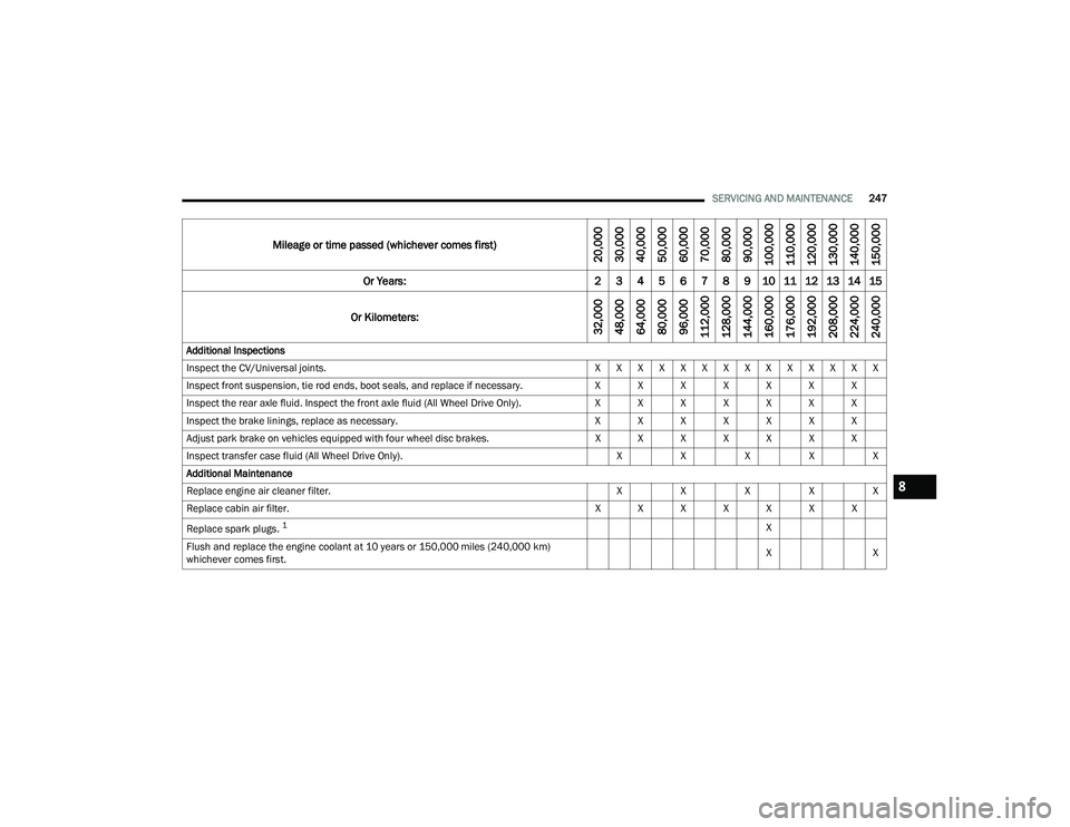
Mileage or time passed (whichever comes first)
20,000
30,000
40,000
50,000
60,000
70,000
80,000
90,000
100,000
110,000
120,000
130,000
140,000
150,000
Or Years: 2 3 4 5 6 7 8 9 10 11 12 13 14 15
Or Kilometers:
32,000
48,000
64,000
80,000
96,000
112,000
128,000
144,000
160,000
176,000
192,000
208,000
224,000
240,000
Additional Inspections
Inspect the CV/Universal joints. X X X X X X X X X X X X X X
Inspect front suspension, tie rod ends, boot seals, and replace if necessary. X X X X X X X
Inspect the rear axle fluid. Inspect the front axle fluid (All Wheel Drive Only). X X X X X X X
Inspect the brake linings, replace as necessary. X X X X X X X
Adjust park brake on vehicles equipped with four wheel disc brakes. X X X X X X X
Inspect transfer case fluid (All Wheel Drive Only). XXXXX
Additional Maintenance
Replace engine air cleaner filter. XXXXX
Replace cabin air filter. X X X X X X X
Replace spark plugs.
1X
Flush and replace the engine coolant at 10 years or 150,000 miles (240,000 km)
whichever comes first. X
X
8
21_LD_OM_EN_USC_t.book Page 247
Page 288 of 320
286SERVICING AND MAINTENANCE
Keep dismounted tires in a cool, dry place with as
little exposure to light as possible. Protect tires
from contact with oil, grease, and gasoline.
Replacement Tires
The tires on your new vehicle provide a balance of
many characteristics. They should be inspected
regularly for wear and correct cold tire inflation
pressures. The manufacturer strongly recommends
that you use tires equivalent to the originals in size,
quality and performance when replacement is
needed
Ú
page 285. Refer to the Tire and Loading
Information placard or the Vehicle Certification
Label for the size designation of your tire. The Load
Index and Speed Symbol for your tire will be found on
the original equipment tire sidewall.
See the Tire Sizing Chart example found in the “Tire
Safety Information” section of this manual for
more information relating to the Load Index and
Speed Symbol of a tire Ú page 275.
It is recommended to replace the two front tires or
two rear tires as a pair. Replacing just one tire can
seriously affect your vehicle’s handling. If you ever
replace a wheel, make sure that the wheel’s
specifications match those of the original wheels.
It is recommended you contact an authorized tire
dealer or original equipment dealer with any
questions you may have on tire specifications or capability. Failure to use equivalent replacement
tires may adversely affect the safety, handling, and
ride of your vehicle.
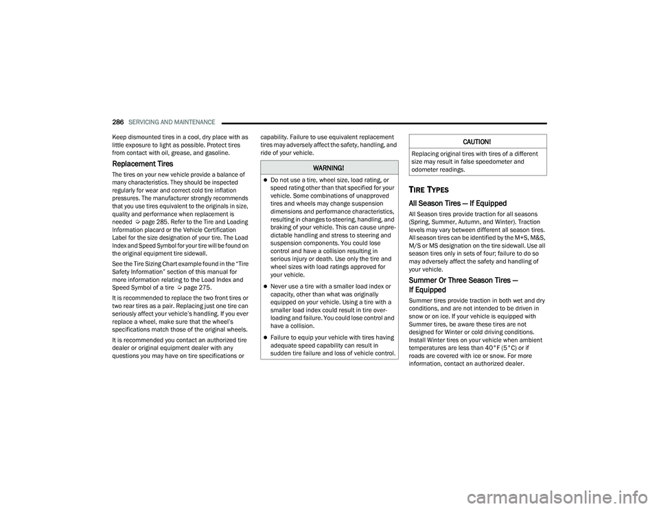
TIRE TYPES
All Season Tires — If Equipped
All Season tires provide traction for all seasons
(Spring, Summer, Autumn, and Winter). Traction
levels may vary between different all season tires.
All season tires can be identified by the M+S, M&S,
M/S or MS designation on the tire sidewall. Use all
season tires only in sets of four; failure to do so
may adversely affect the safety and handling of
your vehicle.
Summer Or Three Season Tires —
If Equipped
Summer tires provide traction in both wet and dry
conditions, and are not intended to be driven in
snow or on ice. If your vehicle is equipped with
Summer tires, be aware these tires are not
designed for Winter or cold driving conditions.
Install Winter tires on your vehicle when ambient
temperatures are less than 40°F (5°C) or if
roads are covered with ice or snow. For more
information, contact an authorized dealer.
WARNING!
Do not use a tire, wheel size, load rating, or
speed rating other than that specified for your
vehicle. Some combinations of unapproved
tires and wheels may change suspension
dimensions and performance characteristics,
resulting in changes to steering, handling, and
braking of your vehicle. This can cause unpre
-
dictable handling and stress to steering and
suspension components. You could lose
control and have a collision resulting in
serious injury or death. Use only the tire and
wheel sizes with load ratings approved for
your vehicle.
Never use a tire with a smaller load index or
capacity, other than what was originally
equipped on your vehicle. Using a tire with a
smaller load index could result in tire over -
loading and failure. You could lose control and
have a collision.
Failure to equip your vehicle with tires having
adequate speed capability can result in
sudden tire failure and loss of vehicle control.
CAUTION!
Replacing original tires with tires of a different
size may result in false speedometer and
odometer readings.
21_LD_OM_EN_USC_t.book Page 286
Page 293 of 320

SERVICING AND MAINTENANCE291
TIRE ROTATION RECOMMENDATIONS
Tires on the front and rear axles of vehicles
operate at different loads and perform different
steering, driving, and braking functions. For these
reasons, they wear at unequal rates.
These effects can be reduced by timely rotation of tires.
The benefits of rotation are especially worthwhile with
aggressive tread designs such as those on all season
type tires. Rotation will increase tread life, help to
maintain mud, snow and wet traction levels, and
contribute to a smooth, quiet ride.
For the proper maintenance intervals Úpage 245.
The reasons for any rapid or unusual wear should
be corrected prior to rotation being performed.
The suggested rotation method is the “rearward
cross” shown in the following diagram. This rotation
pattern does not apply to some directional tires that
must not be reversed. Tire Rotation (Rearward Cross)
DEPARTMENT OF TRANSPORTATION
UNIFORM TIRE QUALITY GRADES
The following tire grading categories
were established by the National
Highway Traffic Safety Administration.
The specific grade rating assigned by the
tire's manufacturer in each category is
shown on the sidewall of the tires on
your vehicle.
All passenger vehicle tires must conform
to Federal safety requirements in
addition to these grades.
CAUTION!
To avoid damage to your vehicle or tires, observe
the following precautions:
Because of restricted traction device clearance
between tires and other suspension components,
it is important that only traction devices in good
condition are used. Broken devices can cause
serious damage. Stop the vehicle immediately if
noise occurs that could indicate device breakage.
Remove the damaged parts of the device before
further use.
Install device as tightly as possible and then
retighten after driving about ½ mile (0.8 km).
Autosock traction devices do not require
retightening.
Do not exceed 30 mph (48 km/h).
Drive cautiously and avoid severe turns and
large bumps, especially with a loaded vehicle.
Do not drive for a prolonged period on dry
pavement.
Observe the traction device manufacturer’s instruc
-
tions on the method of installation, operating
speed, and conditions for use. Always use the
suggested operating speed of the device manufac -
turer’s if it is less than 30 mph (48 km/h).
Do not use traction devices on a compact
spare tire.
8
21_LD_OM_EN_USC_t.book Page 291