Head rest DODGE CHARGER 2022 Owners Manual
[x] Cancel search | Manufacturer: DODGE, Model Year: 2022, Model line: CHARGER, Model: DODGE CHARGER 2022Pages: 312, PDF Size: 18.99 MB
Page 4 of 312
2
INTRODUCTION
SYMBOLS KEY ...........................................................9
VEHICLE MODIFICATIONS/ALTERATIONS .............9
SYMBOL GLOSSARY.................................................9
GETTING TO KNOW YOUR VEHICLE
KEYS ....................................................................... 13 Key Fob .............................................................13
SENTRY KEY ........................................................... 15
IGNITION SWITCH .................................................. 16
Keyless Enter ‘n Go™ Ignition .........................16
REMOTE START — IF EQUIPPED .......................... 17
How To Use Remote Start ................................18
To Exit Remote Start Mode .............................18
Remote Start Front Defrost Activation —
If Equipped........................................................19
Remote Start Comfort Systems —
If Equipped........................................................19
Remote Start Windshield Wiper De–Icer
Activation — If Equipped ..................................20
Remote Start Cancel Message —
If Equipped........................................................20
VEHICLE SECURITY SYSTEM — IF EQUIPPED .... 20
To Arm The System ..........................................20
To Disarm The System .....................................20
Rearming Of The System .................................21
Security System Manual Override ...................21
Tamper Alert .....................................................21 DELUXE VEHICLE SECURITY SYSTEM —
IF EQUIPPED ...........................................................21
To Arm The System ..........................................21
To Disarm The System .....................................22
Security System Manual Override ...................22
DOORS ....................................................................22
Manual Door Locks ..........................................22
Power Door Locks ...........................................23
Keyless Enter ‘n Go™ — Passive Entry ...........24
Automatic Unlock Doors On Exit......................25
Automatic Door Locks —
If Equipped........................................................26
Child-Protection Door Lock System —
Rear Doors .......................................................26
STEERING WHEEL ..................................................26
Manual Tilt/Telescoping Steering Column —
If Equipped .......................................................26
Power Tilt/Telescoping Steering Column —
If Equipped .......................................................27
Heated Steering Wheel —If Equipped .............27
UCONNECT VOICE RECOGNITION ........................28
Introducing Voice Recognition.........................28
Basic Voice Commands ...................................28
Get Started .......................................................28
Additional Information .....................................29 DRIVER MEMORY SETTINGS — IF EQUIPPED ... 29
Programming The Memory Feature ................30
Linking And Unlinking The Key Fob
To Memory ........................................................ 30
Memory Position Recall ................................... 30
SEATS ...................................................................... 31
Manual Adjustment (Front Seats) —
If Equipped .......................................................31
Manual Adjustment (Rear Seats).................... 32
Power Adjustment (Front Seats) —
If Equipped .......................................................33
Heated Seats — If Equipped ............................ 34
Front Ventilated Seats — If Equipped ............. 36
Head Restraints .............................................. 36
MIRRORS ............................................................... 38
Inside Rearview Mirror..................................... 38
Illuminated Vanity Mirrors ............................... 38
Outside Mirrors.................................................39
Driver's Outside Automatic Dimming Mirror —
If Equipped .......................................................39
Power Mirrors ................................................... 39
Heated Mirrors — If Equipped ......................... 40
Tilt Side Mirrors In Reverse —
If Equipped .......................................................40
22_LD_OM_EN_USC_t.book Page 2
Page 38 of 312
36GETTING TO KNOW YOUR VEHICLE
NOTE:
Once a heat setting is selected, heat will be felt
within two to five minutes.
The engine must be running for the heated
seats to operate.
FRONT VENTILATED SEATS —
I
F EQUIPPED
The ventilated seats are equipped with
fans that can be controlled through the
climate and control screen in the
Uconnect system. The fans operate at
two speeds, HI and LO.
Press the ventilated seat button once to choose
HI.
Press the ventilated seat button a second time
to choose LO.
Press the ventilated seat button a third time to
turn the ventilated seat off.
NOTE:The engine must be running for the ventilated
seats to operate.
For information on use with the Remote Start
system, see Ú page 19.
HEAD RESTRAINTS
Head restraints are designed to reduce the risk of
injury by restricting head movement in the event of
a rear impact. Head restraints should be adjusted
so that the top of the head restraint is located
above the top of your ear.
NOTE:Do not reverse the head restraints (making the
rear of the head restraint face forward) in an
attempt to gain additional clearance to the back of
your head.
Reactive Head Restraints — Front Seats
The front driver and passenger seats are equipped
with Reactive Head Restraints (RHR). In the event
of a rear impact, the RHR will automatically extend
forward minimizing the gap between the back of
the occupant’s head and the RHR.
The RHR will automatically return to their normal
position following a rear impact. If the RHR do not
return to their normal position, see an authorized
dealer immediately.
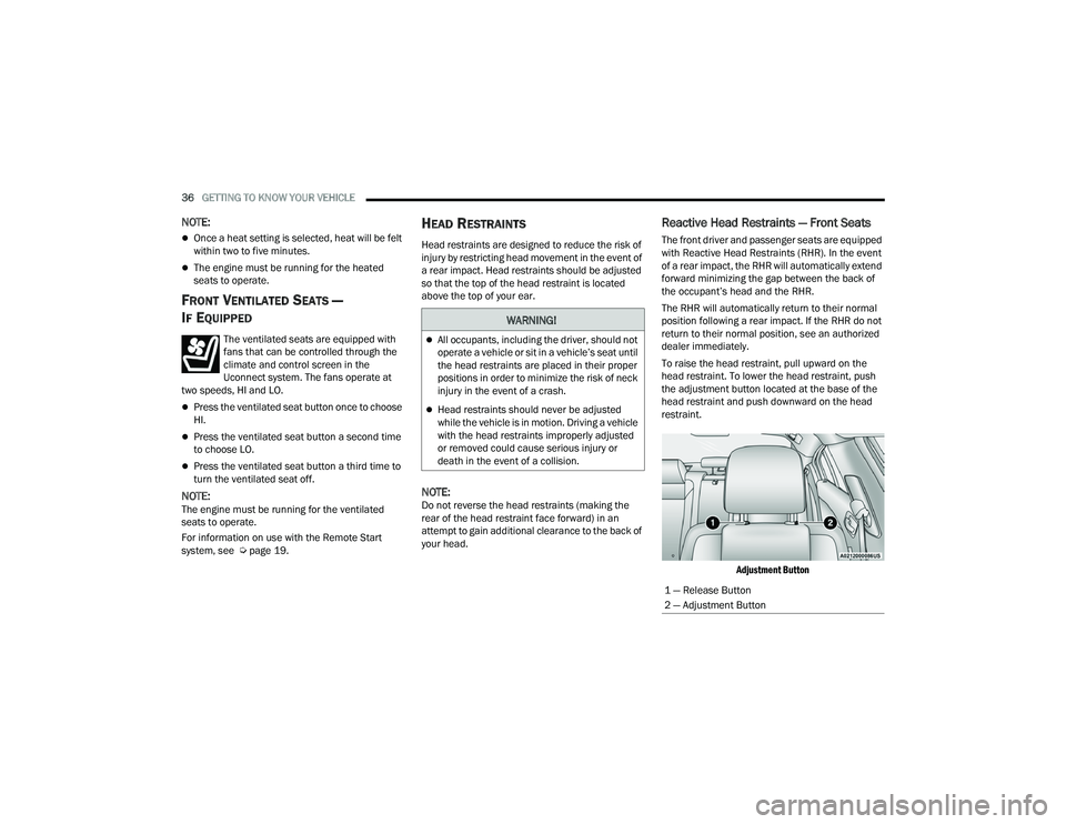
To raise the head restraint, pull upward on the
head restraint. To lower the head restraint, push
the adjustment button located at the base of the
head restraint and push downward on the head
restraint.
Adjustment Button
WARNING!
All occupants, including the driver, should not
operate a vehicle or sit in a vehicle’s seat until
the head restraints are placed in their proper
positions in order to minimize the risk of neck
injury in the event of a crash.
Head restraints should never be adjusted
while the vehicle is in motion. Driving a vehicle
with the head restraints improperly adjusted
or removed could cause serious injury or
death in the event of a collision.
1 — Release Button
2 — Adjustment Button
22_LD_OM_EN_USC_t.book Page 36
Page 39 of 312
GETTING TO KNOW YOUR VEHICLE37
Rear Head Restraints
The center head restraint has two adjustable
positions: up or down. When the center seat is
being occupied, the head restraint should be in the
raised position. When there are no occupants in
the center seat, the head restraint can be lowered
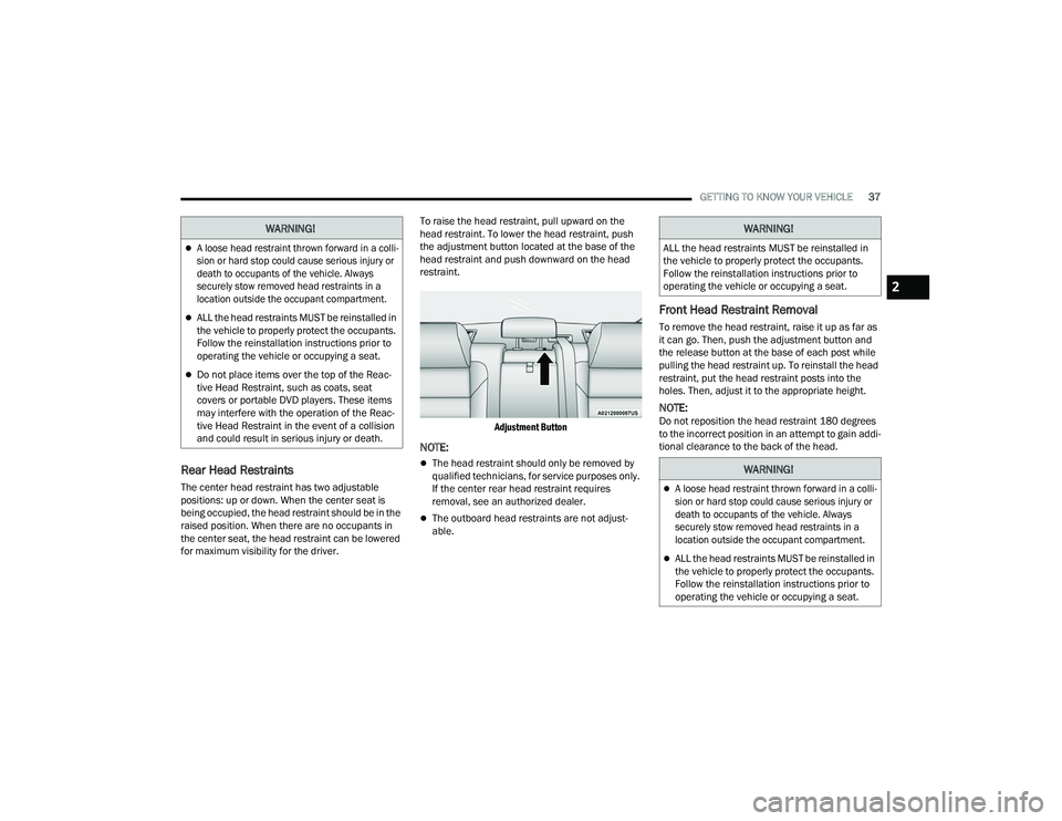
for maximum visibility for the driver. To raise the head restraint, pull upward on the
head restraint. To lower the head restraint, push
the adjustment button located at the base of the
head restraint and push downward on the head
restraint.
Adjustment Button
NOTE:
The head restraint should only be removed by
qualified technicians, for service purposes only.
If the center rear head restraint requires
removal, see an authorized dealer.
The outboard head restraints are not adjust -
able.
Front Head Restraint Removal
To remove the head restraint, raise it up as far as
it can go. Then, push the adjustment button and
the release button at the base of each post while
pulling the head restraint up. To reinstall the head
restraint, put the head restraint posts into the
holes. Then, adjust it to the appropriate height.
NOTE:Do not reposition the head restraint 180 degrees
to the incorrect position in an attempt to gain addi -
tional clearance to the back of the head.
WARNING!
A loose head restraint thrown forward in a colli -
sion or hard stop could cause serious injury or
death to occupants of the vehicle. Always
securely stow removed head restraints in a
location outside the occupant compartment.
ALL the head restraints MUST be reinstalled in
the vehicle to properly protect the occupants.
Follow the reinstallation instructions prior to
operating the vehicle or occupying a seat.
Do not place items over the top of the Reac -
tive Head Restraint, such as coats, seat
covers or portable DVD players. These items
may interfere with the operation of the Reac -
tive Head Restraint in the event of a collision
and could result in serious injury or death.
WARNING!
ALL the head restraints MUST be reinstalled in
the vehicle to properly protect the occupants.
Follow the reinstallation instructions prior to
operating the vehicle or occupying a seat.
WARNING!
A loose head restraint thrown forward in a colli -
sion or hard stop could cause serious injury or
death to occupants of the vehicle. Always
securely stow removed head restraints in a
location outside the occupant compartment.
ALL the head restraints MUST be reinstalled in
the vehicle to properly protect the occupants.
Follow the reinstallation instructions prior to
operating the vehicle or occupying a seat.
2
22_LD_OM_EN_USC_t.book Page 37
Page 73 of 312
GETTING TO KNOW YOUR INSTRUMENT PANEL71
Within each submenu layer, the up and
down arrow buttons will allow the user to
select the item of interest.
Pushing the OK button makes the selection and
a confirmation screen will appear (returning the
user to the first page of the submenu).
Pushing the left arrow button will exit each
submenu layer and return to the main menu.
ENGINE OIL LIFE RESET
Oil Change Required
Your vehicle is equipped with an engine oil change
indicator system. The “Oil Change Required”
message will display in the instrument cluster
display for five seconds after a single chime has
sounded, to indicate the next scheduled oil change
interval. The engine oil change indicator system is
duty cycle based, which means the engine oil
change interval may fluctuate, dependent upon
your personal driving style.
Unless reset, this message will continue to display
each time you place the ignition in the ON/RUN
position. To turn off the message temporarily, push
and release the OK or arrow buttons. To reset the
oil change indicator system (after performing the
scheduled maintenance), refer to the following
procedure. Vehicles Equipped With Keyless Enter ’n Go™ —
Ignition
Use the steering wheel instrument cluster display
controls for the following procedure(s):
1. Without pressing the brake pedal, push the
ENGINE START/STOP button and place the
ignition in the ON/RUN position (do not start
the engine).
2. Push and release the down arrow button to
scroll downward through the main menu to
“Vehicle Info.”
3. Push and release the right arrow button to
access the ”Oil Life” screen.
4. Push and hold the OK button to reset oil life. If
conditions are met, the gauge and numeric
display will update to show 100%. If conditions
are not met a pop-up message of "To reset oil
life engine must be off with ignition in run” will
be displayed (for five seconds), and the user
will remain at the Oil Life screen.
5. Push and release the up or down arrow
button to exit the submenu screen.
NOTE:If the indicator message illuminates when you start
the vehicle, the oil change indicator system did not
reset. If necessary, repeat this procedure. Secondary Method Of Resetting Engine Oil Life
1. Without pressing the brake pedal, push the
ENGINE START/STOP button and place the
ignition to the ON/RUN position (do not start
the engine).
2. Fully press the accelerator pedal, slowly, three times within ten seconds.
3. Without pushing the brake pedal, push the ENGINE START/STOP button once to return the
ignition to the OFF position.
NOTE:If the indicator message illuminates when you start
the vehicle, the oil change indicator system did not
reset. If necessary, repeat this procedure.
PERFORMANCE SHIFT INDICATOR (PSI) —
I
F EQUIPPED
The PSI is enabled on vehicles with manual
transmission, or when a vehicle with automatic
transmission is in manual shift mode. The PSI
provides the driver with a visual indication within
the instrument cluster display when the driver
configured gear shift point has been reached and
the driver is still accelerating. This indication
notifies the driver to change gear corresponding to
the configured RPMs in the head unit.
3
22_LD_OM_EN_USC_t.book Page 71
Page 94 of 312
92STARTING AND OPERATING
DRIVE (D)
This range should be used for most city and
highway driving. It provides the smoothest upshifts
and downshifts, and the best fuel economy. The
transmission automatically upshifts through all
forward gears. The DRIVE position provides
optimum driving characteristics under all normal
operating conditions.
When frequent transmission shifting occurs (such
as when operating the vehicle under heavy loading
conditions, in hilly terrain, traveling into strong
head winds, or while towing a heavy trailer), use
the AutoStick shift control (if equipped) to select a
lower gear Úpage 92. Under these conditions,
using a lower gear will improve performance and
extend transmission life by reducing excessive
shifting and heat buildup.
During extremely cold temperatures (-22°F
[-30°C] or below), transmission operation may be
modified depending on engine and transmission
temperature as well as vehicle speed. Normal
operation will resume once the transmission
temperature has risen to a suitable level.
MANUAL (M)
The MANUAL (M, +/-) position (beside the DRIVE
position) enables full manual control of
transmission shifting (also known as AutoStick
mode) Ú page 92. Toggling the gear selector
forward (-) or rearward (+) while in the MANUAL (AutoStick) position will manually select the
transmission gear, and will display the current gear
in the instrument cluster as M1, M2, M3, etc.
Transmission Limp Home Mode
Transmission function is monitored electronically
for abnormal conditions. If a condition is detected
that could result in transmission damage,
Transmission Limp Home Mode is activated. In this
mode, the transmission may operate only in
certain gears, or may not shift at all. Vehicle
performance may be severely degraded and the
engine may stall. In some situations, the
transmission may not re-engage if the engine is
turned off and restarted. The Malfunction Indicator
Light (MIL) may be illuminated. A message in the
instrument cluster will inform the driver of the
more serious conditions, and indicate what actions
may be necessary.
In the event of a momentary problem, the
transmission can be reset to regain all forward
gears by performing the following steps:
NOTE:In cases where the instrument cluster message
indicates the transmission may not re-engage after
engine shutdown, perform this procedure only in a
desired location (preferably, at an authorized
dealer).
1. Stop the vehicle.
2. Shift the transmission into PARK, if possible. If
not, shift the transmission to NEUTRAL.
3. Push and hold the ignition switch until the engine turns off.
4. Wait approximately 30 seconds.
5. Restart the engine.
6. Shift into the desired gear range. If the problem is no longer detected, the
transmission will return to normal operation.
NOTE:Even if the transmission can be reset, we
recommend that you visit an authorized dealer at
your earliest possible convenience. An authorized
dealer has diagnostic equipment to assess the
condition of your transmission. If the transmission
cannot be reset, authorized dealer service is
required.
AutoStick — If Equipped
AutoStick is a driver-interactive transmission
feature providing manual shift control, giving you
more control of the vehicle. AutoStick allows you to
maximize engine braking, eliminate undesirable
upshifts and downshifts, and improve overall
vehicle performance. This system can also provide
you with more control during passing, city driving,
cold slippery conditions, mountain driving, trailer
towing, and many other situations.
22_LD_OM_EN_USC_t.book Page 92
Page 196 of 312
194SAFETY
(Continued)
The SABIC deploys downward, covering the side
windows. An inflating SABIC pushes the outside
edge of the headliner out of the way and covers the
window. The SABICs inflate with enough force to
injure occupants if they are not belted and seated
properly, or if items are positioned in the area
where the SABICs inflate. Children are at an even
greater risk of injury from a deploying air bag.
The SABICs may help reduce the risk of partial or
complete ejection of vehicle occupants through
side windows in certain side impact events.
Side Impacts
The Side Air Bags are designed to activate in
certain side impacts. The Occupant Restraint
Controller (ORC) determines whether the
deployment of the Side Air Bags in a particular
impact event is appropriate, based on the severity
and type of collision. The side impact sensors aid
the ORC in determining the appropriate response
to impact events. The system is calibrated to
deploy the Side Air Bags on the impact side of the
vehicle during impacts that require Side Air Bag
occupant protection. In side impacts, the Side Air
Bags deploy independently; a left side impact
deploys the left Side Air Bags only and a right-side
impact deploys the right Side Air Bags only. Vehicle
damage by itself is not a good indicator of whether
or not Side Air Bags should have deployed.
The Side Air Bags will not deploy in all side
collisions, including some collisions at certain
angles, or some side collisions that do not impact
the area of the passenger compartment. The Side
Air Bags may deploy during angled or offset frontal
collisions where the front air bags deploy.
Side Air Bags are a supplement to the seat belt
restraint system. Side Air Bags deploy in less time
than it takes to blink your eyes.
WARNING!
Do not mount equipment, or stack luggage or
other cargo up high enough to block the
deployment of the SABICs. The trim covering
above the side windows where the SABIC and
its deployment path are located should
remain free from any obstructions.
In order for the SABICs to work as intended, do
not install any accessory items in your vehicle
which could alter the roof. Do not add an after
-
market sunroof to your vehicle. Do not add
roof racks that require permanent attach -
ments (bolts or screws) for installation on the
vehicle roof. Do not drill into the roof of the
vehicle for any reason.
WARNING!
Occupants, including children, who are up
against or very close to Side Air Bags can be
seriously injured or killed. Occupants,
including children, should never lean on or
sleep against the door, side windows, or area
where the side air bags inflate, even if they are
in an infant or child restraint.
Seat belts (and child restraints where appro -
priate) are necessary for your protection in all
collisions. They also help keep you in position,
away from an inflating Side Air Bag. To get the
best protection from the Side Air Bags, occu -
pants must wear their seat belts properly and
sit upright with their backs against the seats.
Children must be properly restrained in a child
restraint or booster seat that is appropriate for
the size of the child.
WARNING!
Side Air Bags need room to inflate. Do not lean
against the door or window. Sit upright in the
center of the seat.
Being too close to the Side Air Bags during
deployment could cause you to be severely
injured or killed.
22_LD_OM_EN_USC_t.book Page 194
Page 198 of 312
196SAFETY
Do not drive your vehicle after the air bags have
deployed. If you are involved in another collision,
the air bags will not be in place to protect you.
NOTE:
Air bag covers may not be obvious in the interior
trim, but they will open during air bag deploy -
ment.
After any collision, the vehicle should be taken
to an authorized dealer immediately.
Enhanced Accident Response System
In the event of an impact, if the communication
network remains intact, and the power remains
intact, depending on the nature of the event, the
Occupant Restraint Controller (ORC) will determine
whether to have the Enhanced Accident Response
System perform the following functions:
Cut off fuel to the engine (if equipped).
Cut off battery power to the electric motor (if
equipped).
Flash hazard lights as long as the battery has
power.
Turn on the interior lights, which remain on as
long as the battery has power or for 15 minutes
from the intervention of the Enhanced Accident
Response System.
Unlock the power door locks.
Your vehicle may also be designed to perform any
of these other functions in response to the
Enhanced Accident Response System:
Turn off the Fuel Filter Heater, Turn off the HVAC
Blower Motor, Close the HVAC Circulation Door
Cut off battery power to the:
Engine
Electric Motor (if equipped)
Electric power steering
Brake booster
Electric park brake
Automatic transmission gear selector
Horn
Front wiper
Headlamp washer pump (if equipped)
NOTE:After an accident, remember to cycle the ignition to
the STOP (OFF/LOCK) position and remove the key
from the ignition switch to avoid draining the
battery. Carefully check the vehicle for fuel leaks in
the engine compartment and on the ground near
the engine compartment and fuel tank before
resetting the system and starting the engine. If
there are no fuel leaks or damage to the vehicle
electrical devices (e.g. headlights) after an
accident, reset the system by following the
procedure described below. If you have any doubt,
contact an authorized dealer.
Enhanced Accident Response System
Reset Procedure
In order to reset the Enhanced Accident Response
System functions after an event, the ignition switch
must be changed from ignition START or ON/RUN
to ignition OFF. Carefully check the vehicle for fuel
leaks in the engine compartment and on the
ground near the engine compartment and fuel
tank before resetting the system and starting the
engine.
After an accident, if the vehicle will not start after
performing the reset procedure, the vehicle must
be towed to an authorized dealer to be inspected
and to have the Enhanced Accident Response
System reset.
WARNING!
Deployed air bags and seat belt pretensioners
cannot protect you in another collision. Have the
air bags, seat belt pretensioners, and the seat
belt retractor assemblies replaced by an
authorized dealer immediately. Also, have the
Occupant Restraint Controller System serviced
as well.
22_LD_OM_EN_USC_t.book Page 196
Page 205 of 312
SAFETY203
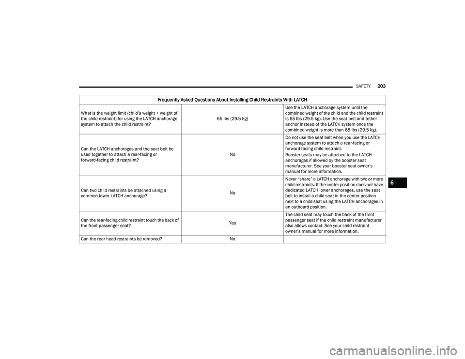
Frequently Asked Questions About Installing Child Restraints With LATCH
What is the weight limit (child’s weight + weight of
the child restraint) for using the LATCH anchorage
system to attach the child restraint? 65 lbs (29.5 kg)Use the LATCH anchorage system until the
combined weight of the child and the child restraint
is 65 lbs (29.5 kg). Use the seat belt and tether
anchor instead of the LATCH system once the
combined weight is more than 65 lbs (29.5 kg).
Can the LATCH anchorages and the seat belt be
used together to attach a rear-facing or
forward-facing child restraint? NoDo not use the seat belt when you use the LATCH
anchorage system to attach a rear-facing or
forward-facing child restraint.
Booster seats may be attached to the LATCH
anchorages if allowed by the booster seat
manufacturer. See your booster seat owner’s
manual for more information.
Can two child restraints be attached using a
common lower LATCH anchorage? NoNever “share” a LATCH anchorage with two or more
child restraints. If the center position does not have
dedicated LATCH lower anchorages, use the seat
belt to install a child seat in the center position
next to a child seat using the LATCH anchorages in
an outboard position.
Can the rear-facing child restraint touch the back of
the front passenger seat? YesThe child seat may touch the back of the front
passenger seat if the child restraint manufacturer
also allows contact. See your child restraint
owner’s manual for more information.
Can the rear head restraints be removed? No
6
22_LD_OM_EN_USC_t.book Page 203
Page 207 of 312
SAFETY205
Always follow the directions of the child restraint
manufacturer when installing your child restraint.
Not all child restraint systems will be installed as
described here.
To Install A LATCH-Compatible Child
Restraint
If the selected seating position has a Switchable
Automatic Locking Retractor (ALR) seat belt, stow
the seat belt, following the instructions below. See
Ú page 206 to check what type of seat belt each
seating position has.
1. Loosen the adjusters on the lower straps and on the tether strap of the child seat so that
you can more easily attach the hooks or
connectors to the vehicle anchorages.
2. Place the child seat between the lower anchorages for that seating position. If the
second row seat can be reclined, you may
recline the seat and/or raise the head restraint
(if adjustable) to get a better fit. If the rear seat
can be moved forward and rearward in the
vehicle, you may wish to move it to its
rear-most position to make room for the child
seat. You may also move the front seat forward
to allow more room for the child seat. 3. Attach the lower hooks or connectors of the
child restraint to the lower anchorages in the
selected seating position.
4. If the child restraint has a tether strap, connect it to the top tether anchorage. See
Úpage 208 for directions to attach a tether
anchor.
5. Tighten all of the straps as you push the child restraint rearward and downward into the
seat. Remove slack in the straps according to
the child restraint manufacturer’s instructions.
6. Test that the child restraint is installed tightly by pulling back and forth on the child seat at
the belt path. It should not move more than
1 inch (25.4 mm) in any direction.
How To Stow An Unused Switchable-ALR
Seat Belt:
When using the LATCH attaching system to install
a child restraint, stow all ALR seat belts that are not
being used by other occupants or being used to
secure child restraints. An unused belt could injure
a child if they play with it and accidentally lock the
seat belt retractor. Before installing a child
restraint using the LATCH system, buckle the seat
belt behind the child restraint and out of the child’s
reach. If the buckled seat belt interferes with the
child restraint installation, instead of buckling it
behind the child restraint, route the seat belt
through the child restraint belt path and then
buckle it. Do not lock the seat belt. Remind all
children in the vehicle that the seat belts are not
toys and that they should not play with them.
6
22_LD_OM_EN_USC_t.book Page 205
Page 209 of 312
SAFETY207
Installing A Child Restraint With A
Switchable Automatic Locking Retractor
(ALR):
Child restraint systems are designed to be secured
in vehicle seats by lap belts or the lap belt portion
of a lap/shoulder belt. 7. Place the child seat in the center of the seating
position. If the second row seat can be
reclined, you may recline the seat and/or raise
the head restraint (if adjustable) to get a better
fit. If the rear seat can be moved forward and
rearward in the vehicle, you may wish to move
it to its rear-most position to make room for the
child seat. You may also move the front seat
forward to allow more room for the child seat.
8. Pull enough of the seat belt webbing from the retractor to pass it through the belt path of the
child restraint. Do not twist the belt webbing in
the belt path.
9. Slide the latch plate into the buckle until you hear a “click.” 10. Pull on the webbing to make the lap portion
tight against the child seat.
11. To lock the seat belt, pull down on the shoulder part of the belt until you have pulled all the
seat belt webbing out of the retractor. Then,
allow the webbing to retract back into the
retractor. As the webbing retracts, you will hear
a clicking sound. This means the seat belt is
now in the Automatic Locking mode.
12. Try to pull the webbing out of the retractor. If it is locked, you should not be able to pull out any
webbing. If the retractor is not
locked, repeat
step 5.
13. Finally, pull up on any excess webbing to tighten the lap portion around the child
restraint while you push the child restraint
rearward and downward into the vehicle seat.
Frequently Asked Questions About Installing Child Restraints With Seat Belts
What is the weight limit (child’s weight + weight of
the child restraint) for using the Tether Anchor with
the seat belt to attach a forward facing child
restraint? Weight limit of the Child RestraintAlways use the tether anchor when using the seat
belt to install a forward facing child restraint, up to
the recommended weight limit of the child
restraint.
Can the rear-facing child restraint touch the back of
the front passenger seat? YesContact between the front passenger seat and the
child restraint is allowed, if the child restraint
manufacturer also allows contact.
Can the rear head restraints be removed? No
Can the buckle stalk be twisted to tighten the seat
belt against the belt path of the child restraint? NoDo not twist the buckle stalk in a seating position
with an ALR retractor.
WARNING!
Improper installation or failure to properly
secure a child restraint can lead to failure of
the restraint. The child could be badly injured
or killed.
Follow the child restraint manufacturer’s
directions exactly when installing an infant or
child restraint.
6
22_LD_OM_EN_USC_t.book Page 207