length DODGE CHARGER 2022 Owners Manual
[x] Cancel search | Manufacturer: DODGE, Model Year: 2022, Model line: CHARGER, Model: DODGE CHARGER 2022Pages: 312, PDF Size: 18.99 MB
Page 28 of 312
26GETTING TO KNOW YOUR VEHICLE
3. The gear selector was not in PARK, then is placed in PARK.
4. The driver door is opened.
5. The doors were not previously unlocked.
AUTOMATIC DOOR LOCKS —
I
F EQUIPPED
The auto door lock feature default condition is
enabled. When enabled, the door locks will lock
automatically when the vehicle's speed exceeds
15 mph (24 km/h). The auto door lock feature is
enabled/disabled within Uconnect Settings
Ú page 123.
CHILD-PROTECTION DOOR LOCK
S
YSTEM — REAR DOORS
To provide a safer environment for small children
riding in the rear seats, the rear doors are
equipped with a Child-Protection Door Lock
system.
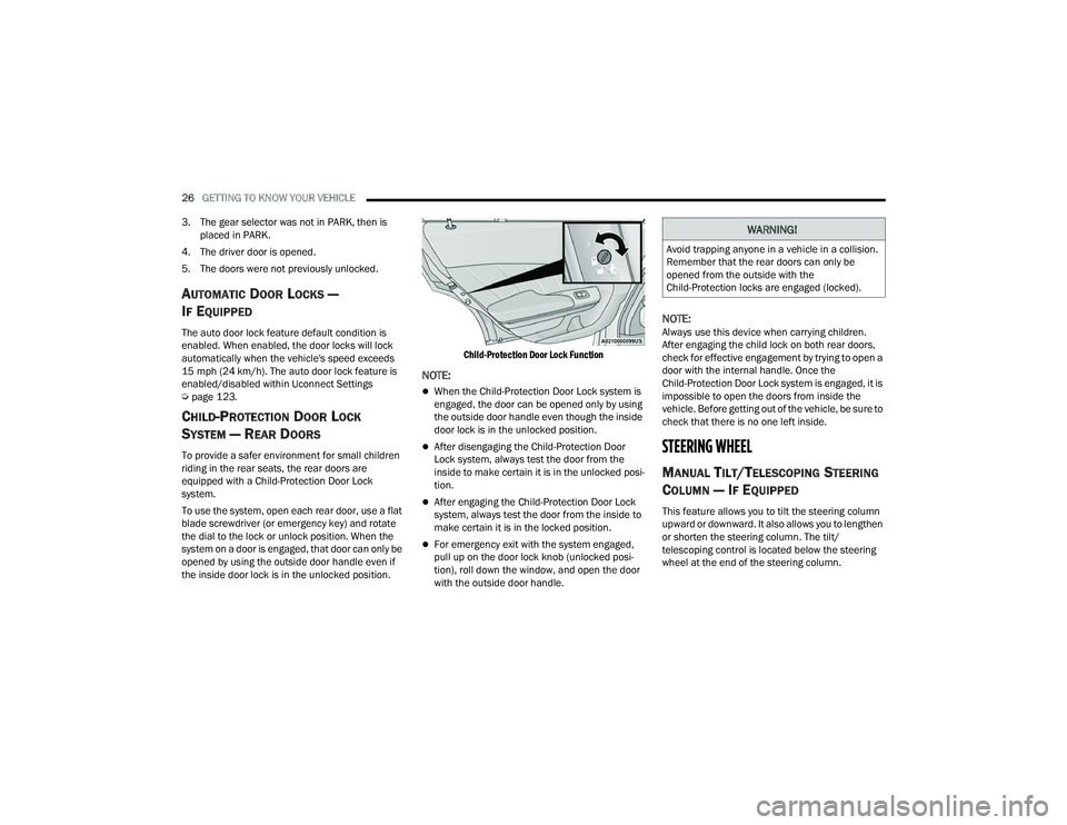
To use the system, open each rear door, use a flat
blade screwdriver (or emergency key) and rotate
the dial to the lock or unlock position. When the
system on a door is engaged, that door can only be
opened by using the outside door handle even if
the inside door lock is in the unlocked position.
Child-Protection Door Lock Function
NOTE:
When the Child-Protection Door Lock system is
engaged, the door can be opened only by using
the outside door handle even though the inside
door lock is in the unlocked position.
After disengaging the Child-Protection Door
Lock system, always test the door from the
inside to make certain it is in the unlocked posi
-
tion.
After engaging the Child-Protection Door Lock
system, always test the door from the inside to
make certain it is in the locked position.
For emergency exit with the system engaged,
pull up on the door lock knob (unlocked posi -
tion), roll down the window, and open the door
with the outside door handle.
NOTE:Always use this device when carrying children.
After engaging the child lock on both rear doors,
check for effective engagement by trying to open a
door with the internal handle. Once the
Child-Protection Door Lock system is engaged, it is
impossible to open the doors from inside the
vehicle. Before getting out of the vehicle, be sure to
check that there is no one left inside.
STEERING WHEEL
MANUAL TILT/TELESCOPING STEERING
C
OLUMN — IF EQUIPPED
This feature allows you to tilt the steering column
upward or downward. It also allows you to lengthen
or shorten the steering column. The tilt/
telescoping control is located below the steering
wheel at the end of the steering column.
WARNING!
Avoid trapping anyone in a vehicle in a collision.
Remember that the rear doors can only be
opened from the outside with the
Child-Protection locks are engaged (locked).
22_LD_OM_EN_USC_t.book Page 26
Page 29 of 312
GETTING TO KNOW YOUR VEHICLE27
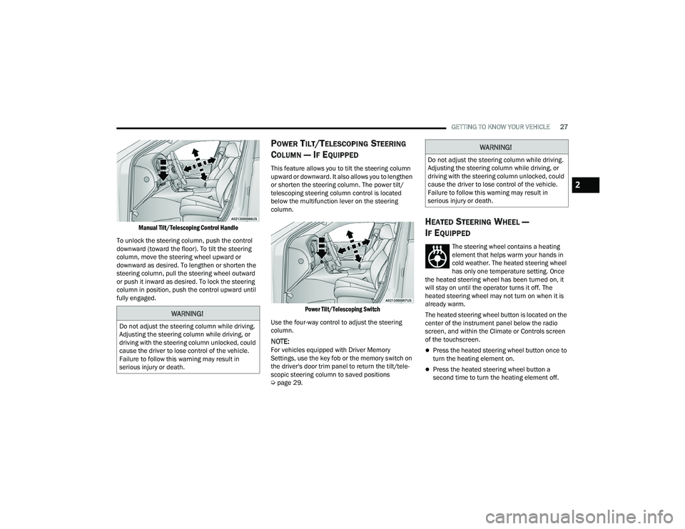
Manual Tilt/Telescoping Control Handle
To unlock the steering column, push the control
downward (toward the floor). To tilt the steering
column, move the steering wheel upward or
downward as desired. To lengthen or shorten the
steering column, pull the steering wheel outward
or push it inward as desired. To lock the steering
column in position, push the control upward until
fully engaged.
POWER TILT/TELESCOPING STEERING
C
OLUMN — IF EQUIPPED
This feature allows you to tilt the steering column
upward or downward. It also allows you to lengthen
or shorten the steering column. The power tilt/
telescoping steering column control is located
below the multifunction lever on the steering
column.
Power Tilt/Telescoping Switch
Use the four-way control to adjust the steering
column.
NOTE:For vehicles equipped with Driver Memory
Settings, use the key fob or the memory switch on
the driver's door trim panel to return the tilt/tele -
scopic steering column to saved positions
Ú page 29.
HEATED STEERING WHEEL —
I
F EQUIPPED
The steering wheel contains a heating
element that helps warm your hands in
cold weather. The heated steering wheel
has only one temperature setting. Once
the heated steering wheel has been turned on, it
will stay on until the operator turns it off. The
heated steering wheel may not turn on when it is
already warm.
The heated steering wheel button is located on the
center of the instrument panel below the radio
screen, and within the Climate or Controls screen
of the touchscreen.
Press the heated steering wheel button once to
turn the heating element on.
Press the heated steering wheel button a
second time to turn the heating element off.
WARNING!
Do not adjust the steering column while driving.
Adjusting the steering column while driving, or
driving with the steering column unlocked, could
cause the driver to lose control of the vehicle.
Failure to follow this warning may result in
serious injury or death.
WARNING!
Do not adjust the steering column while driving.
Adjusting the steering column while driving, or
driving with the steering column unlocked, could
cause the driver to lose control of the vehicle.
Failure to follow this warning may result in
serious injury or death.
2
22_LD_OM_EN_USC_t.book Page 27
Page 63 of 312
GETTING TO KNOW YOUR VEHICLE61
(Continued)
WINDOWS
POWER WINDOW CONTROLS
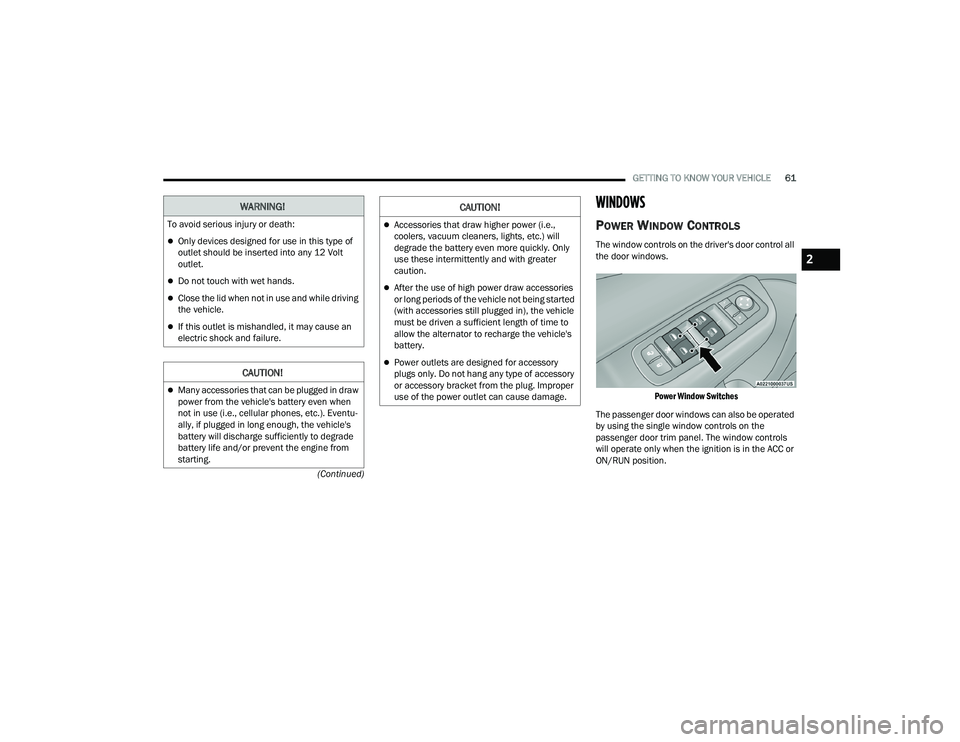
The window controls on the driver's door control all
the door windows.
Power Window Switches
The passenger door windows can also be operated
by using the single window controls on the
passenger door trim panel. The window controls
will operate only when the ignition is in the ACC or
ON/RUN position.
WARNING!
To avoid serious injury or death:
Only devices designed for use in this type of
outlet should be inserted into any 12 Volt
outlet.
Do not touch with wet hands.
Close the lid when not in use and while driving
the vehicle.
If this outlet is mishandled, it may cause an
electric shock and failure.
CAUTION!
Many accessories that can be plugged in draw
power from the vehicle's battery even when
not in use (i.e., cellular phones, etc.). Eventu -
ally, if plugged in long enough, the vehicle's
battery will discharge sufficiently to degrade
battery life and/or prevent the engine from
starting.
Accessories that draw higher power (i.e.,
coolers, vacuum cleaners, lights, etc.) will
degrade the battery even more quickly. Only
use these intermittently and with greater
caution.
After the use of high power draw accessories
or long periods of the vehicle not being started
(with accessories still plugged in), the vehicle
must be driven a sufficient length of time to
allow the alternator to recharge the vehicle's
battery.
Power outlets are designed for accessory
plugs only. Do not hang any type of accessory
or accessory bracket from the plug. Improper
use of the power outlet can cause damage.
CAUTION!
2
22_LD_OM_EN_USC_t.book Page 61
Page 129 of 312
MULTIMEDIA127
Voice
Clock
When the Voice button is pressed on the touchscreen, the system displays the options related to the vehicle’s Voice Recognition feature.
NOTE:Depending on the vehicle’s options, feature settings may vary.
Setting Name Description
Voice Response LengthThis setting will change the response length for the Voice Recognition system.
The “Brief” setting provides a shortened audio description from the system. The “Detailed” setting provides the full audio description from the system.
Show Command List This setting will allow you to turn the Command List on or off. The “Always”
setting will always show the Command List. The “With Help” setting will show
the Command List and provide a brief description of what the command does. The “Never” setting will turn the Command List off.
When the Clock button is pressed on the touchscreen, the system displays the different options related to the vehicle’s internal clock.
NOTE:Depending on the vehicle’s options, feature settings may vary.
Setting Name Description
Sync Time With GPSThis setting will sync the time to the GPS receiver in the system. The system
will control the time via the GPS location.
Time Format This setting will allow you set the time format (AM/PM). Sync Time With GPS
must be off for this setting to be available. The “12 hrs” setting will set the
time to a 12-hour format. The “24 hrs” setting will set the time to a 24-hour format.
5
22_LD_OM_EN_USC_t.book Page 127
Page 176 of 312
174SAFETY
AUXILIARY DRIVING SYSTEMS
BLIND SPOT MONITORING (BSM) —
I
F EQUIPPED
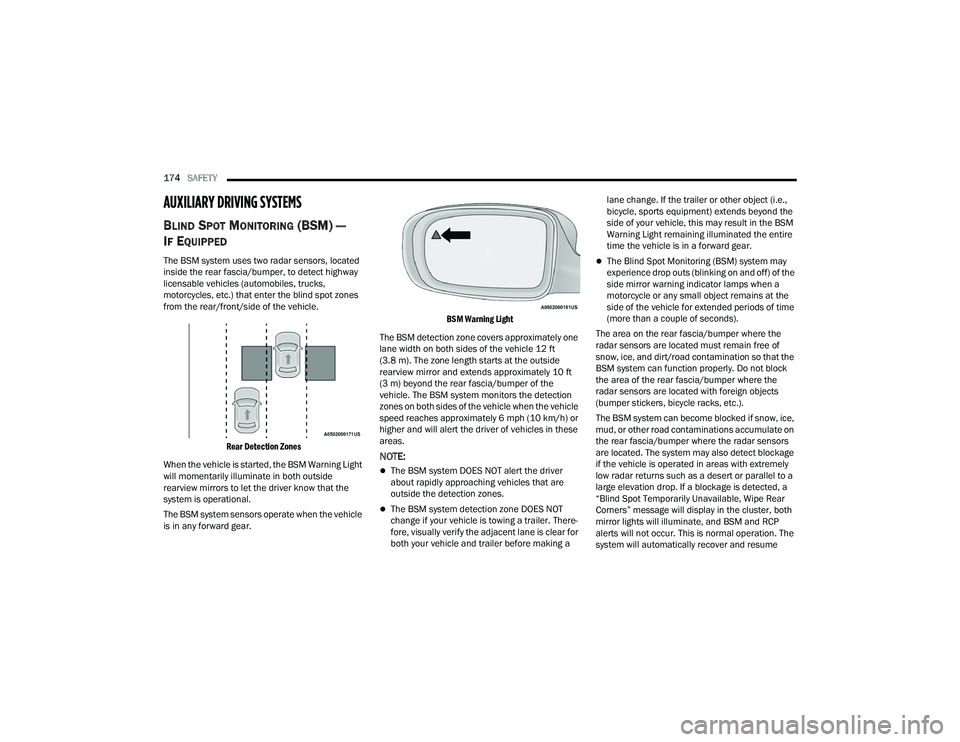
The BSM system uses two radar sensors, located
inside the rear fascia/bumper, to detect highway
licensable vehicles (automobiles, trucks,
motorcycles, etc.) that enter the blind spot zones
from the rear/front/side of the vehicle.
Rear Detection Zones
When the vehicle is started, the BSM Warning Light
will momentarily illuminate in both outside
rearview mirrors to let the driver know that the
system is operational.
The BSM system sensors operate when the vehicle
is in any forward gear.
BSM Warning Light
The BSM detection zone covers approximately one
lane width on both sides of the vehicle 12 ft
(3.8 m). The zone length starts at the outside
rearview mirror and extends approximately 10 ft
(3 m) beyond the rear fascia/bumper of the
vehicle. The BSM system monitors the detection
zones on both sides of the vehicle when the vehicle
speed reaches approximately 6 mph (10 km/h) or
higher and will alert the driver of vehicles in these
areas.
NOTE:
The BSM system DOES NOT alert the driver
about rapidly approaching vehicles that are
outside the detection zones.
The BSM system detection zone DOES NOT
change if your vehicle is towing a trailer. There -
fore, visually verify the adjacent lane is clear for
both your vehicle and trailer before making a lane change. If the trailer or other object (i.e.,
bicycle, sports equipment) extends beyond the
side of your vehicle, this may result in the BSM
Warning Light remaining illuminated the entire
time the vehicle is in a forward gear.
The Blind Spot Monitoring (BSM) system may
experience drop outs (blinking on and off) of the
side mirror warning indicator lamps when a
motorcycle or any small object remains at the
side of the vehicle for extended periods of time
(more than a couple of seconds).
The area on the rear fascia/bumper where the
radar sensors are located must remain free of
snow, ice, and dirt/road contamination so that the
BSM system can function properly. Do not block
the area of the rear fascia/bumper where the
radar sensors are located with foreign objects
(bumper stickers, bicycle racks, etc.).
The BSM system can become blocked if snow, ice,
mud, or other road contaminations accumulate on
the rear fascia/bumper where the radar sensors
are located. The system may also detect blockage
if the vehicle is operated in areas with extremely
low radar returns such as a desert or parallel to a
large elevation drop. If a blockage is detected, a
“Blind Spot Temporarily Unavailable, Wipe Rear
Corners” message will display in the cluster, both
mirror lights will illuminate, and BSM and RCP
alerts will not occur. This is normal operation. The
system will automatically recover and resume
22_LD_OM_EN_USC_t.book Page 174