tire type DODGE CHARGER 2022 Owners Manual
[x] Cancel search | Manufacturer: DODGE, Model Year: 2022, Model line: CHARGER, Model: DODGE CHARGER 2022Pages: 312, PDF Size: 18.99 MB
Page 8 of 312
6
IN CASE OF EMERGENCY
HAZARD WARNING FLASHERS ........................ 213
ASSIST AND SOS MIRROR — IF EQUIPPED...... 213
JACKING AND TIRE CHANGING.......................... 216 Preparations For Jacking .............................. 216Jack Location/Spare Tire Stowage .............. 217
Jacking Instructions ...................................... 218
TIRE SERVICE KIT — IF EQUIPPED ..................... 221
Tire Service Kit Storage ................................ 221
Tire Service Kit Components And Operation ....221
Tire Service Kit Usage Precautions .............. 221
Sealing A Tire With Tire Service Kit .............. 223
JUMP STARTING .................................................. 225
Preparations For Jump Start......................... 226Jump Starting Procedure .............................. 226
REFUELING IN EMERGENCY .............................. 227
IF YOUR ENGINE OVERHEATS ........................... 228
MANUAL PARK RELEASE–8–SPEED
TRANSMISSION.................................................... 229 FREEING A STUCK VEHICLE ............................... 231
TOWING A DISABLED VEHICLE ......................... 232 All Wheel Drive (AWD) Models ...................... 233Rear Wheel Drive (RWD) Models ................ 233
Without The Key Fob ..................................... 233
ENHANCED ACCIDENT RESPONSE SYSTEM
(EARS) .................................................................. 233
EVENT DATA RECORDER (EDR) ........................ 233
SERVICING AND MAINTENANCE
SCHEDULED SERVICING ................................... 234
3.6L And 5.7L Engines ................................. 234
ENGINE COMPARTMENT .................................... 238
3.6L Engine .................................................. 238
5.7L Engine .................................................. 239
Checking Oil Level ......................................... 240
Adding Washer Fluid ..................................... 240
Maintenance-Free Battery ........................... 241Pressure Washing ......................................... 241 VEHICLE MAINTENANCE ..................................... 241
Engine Oil....................................................... 242Engine Oil Filter ............................................. 242Engine Air Cleaner Filter .............................. 243
Air Conditioner Maintenance ....................... 243
Accessory Drive Belt Inspection ................... 244Body Lubrication ........................................... 245
Windshield Wiper Blades.............................. 245
Exhaust System ............................................. 247Cooling System ............................................. 248Brake System ............................................... 251Automatic Transmission ............................... 251
Rear Axle........................................................ 252
Fuses.............................................................. 252
Bulb Replacement ........................................ 261
TIRES ..................................................................... 264
Tire Safety Information ................................ 264Tires — General Information ........................ 273Tire Types....................................................... 276Spare Tires — If Equipped............................. 277Wheel And Wheel Trim Care ........................ 279Snow Traction Devices ................................. 280
Tire Rotation Recommendations ................. 281
22_LD_OM_EN_USC_t.book Page 6
Page 83 of 312
GETTING TO KNOW YOUR INSTRUMENT PANEL81
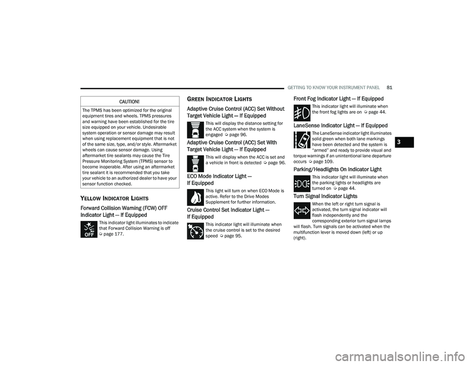
YELLOW INDICATOR LIGHTS
Forward Collision Warning (FCW) OFF
Indicator Light — If Equipped
This indicator light illuminates to indicate
that Forward Collision Warning is off
Úpage 177.
GREEN INDICATOR LIGHTS
Adaptive Cruise Control (ACC) Set Without
Target Vehicle Light — If Equipped
This will display the distance setting for
the ACC system when the system is
engaged Ú page 96.
Adaptive Cruise Control (ACC) Set With
Target Vehicle Light — If Equipped
This will display when the ACC is set and
a vehicle in front is detected Ú page 96.
ECO Mode Indicator Light —
If Equipped
This light will turn on when ECO Mode is
active. Refer to the Drive Modes
Supplement for further information.
Cruise Control Set Indicator Light —
If Equipped
This indicator light will illuminate when
the cruise control is set to the desired
speed Úpage 95.
Front Fog Indicator Light — If Equipped
This indicator light will illuminate when
the front fog lights are on Ú page 44.
LaneSense Indicator Light — If Equipped
The LaneSense indicator light illuminates
solid green when both lane markings
have been detected and the system is
“armed” and ready to provide visual and
torque warnings if an unintentional lane departure
occurs Ú page 109.
Parking/Headlights On Indicator Light
This indicator light will illuminate when
the parking lights or headlights are
turned on Ú page 44.
Turn Signal Indicator Lights
When the left or right turn signal is
activated, the turn signal indicator will
flash independently and the
corresponding exterior turn signal lamps
will flash. Turn signals can be activated when the
multifunction lever is moved down (left) or up
(right).
CAUTION!
The TPMS has been optimized for the original
equipment tires and wheels. TPMS pressures
and warning have been established for the tire
size equipped on your vehicle. Undesirable
system operation or sensor damage may result
when using replacement equipment that is not
of the same size, type, and/or style. Aftermarket
wheels can cause sensor damage. Using
aftermarket tire sealants may cause the Tire
Pressure Monitoring System (TPMS) sensor to
become inoperable. After using an aftermarket
tire sealant it is recommended that you take
your vehicle to an authorized dealer to have your
sensor function checked.
3
22_LD_OM_EN_USC_t.book Page 81
Page 116 of 312
114STARTING AND OPERATING
VEHICLE LOADING
The load carrying capacity of your vehicle is shown
on the Vehicle Certification Label. This information
should be used for passenger and luggage loading
as indicated.
Do not exceed the specified Gross Vehicle Weight
Rating (GVWR) or the Gross Axle Weight Rating
(GAWR).
VEHICLE CERTIFICATION LABEL
Your vehicle has a Vehicle Certification Label
affixed to the driver’s side B-pillar or the rear of the
driver’s door.
The label contains the following information:
Name of manufacturer.
Month and year of manufacture.
Gross Vehicle Weight Rating (GVWR).
Gross Axle Weight Rating (GAWR) front.
Gross Axle Weight Rating (GAWR) rear.
Vehicle Identification Number (VIN).
Type of vehicle.
Month, Day, and Hour (MDH) of manufacture.
The bar code allows a computer scanner to read
the VIN.
GROSS VEHICLE WEIGHT RATING
(GVWR)
The GVWR is the total allowable weight of your
vehicle. This includes driver, passengers, and
cargo. The total load must be limited so that you do
not exceed the GVWR.
GROSS AXLE WEIGHT RATING (GAWR)
The GAWR is the maximum capacity of the front
and rear axles. Distribute the load over the front
and rear axles evenly. Make sure that you do not
exceed either front or rear GAWR.
OVERLOADING
The load carrying components (axle, springs, tires,
wheels, etc.) of your vehicle will provide
satisfactory service as long as you do not exceed
the GVWR and the front and rear GAWR.
The best way to figure out the total weight of your
vehicle is to weigh it when it is fully loaded and
ready for operation. Weigh it on a commercial scale
to ensure that it is not over the GVWR.
Figure out the weight on the front and rear of the
vehicle separately. It is important that you
distribute the load evenly over the front and rear
axles.
Never add fuel when the engine is running.
This is in violation of most state and federal
fire regulations and may cause the Malfunc -
tion Indicator Light to turn on.
A fire may result if fuel is pumped into a
portable container that is inside of a vehicle.
You could be burned. Always place fuel
containers on the ground while filling.
CAUTION!
To avoid fuel spillage and overfilling, do not “top
off” the fuel tank after filling.
WARNING!
WARNING!
Because the front wheels steer the vehicle, it is
important that you do not exceed the maximum
front or rear GAWR. A dangerous driving
condition can result if either rating is exceeded.
You could lose control of the vehicle and have a
collision.
22_LD_OM_EN_USC_t.book Page 114
Page 117 of 312
STARTING AND OPERATING115
Overloading can cause potential safety hazards
and shorten useful service life. Heavier axles or
suspension components do not necessarily
increase the vehicle's GVWR.
LOADING
To load your vehicle properly, first figure out its
empty weight, axle-by-axle and side-by-side. Store
heavier items down low and be sure you distribute
their weight as evenly as possible. Stow all loose
items securely before driving. If weighing the
loaded vehicle shows that you have exceeded
either GAWR, but the total load is within the
specified GVWR, you must redistribute the weight.
Improper weight distribution can have an adverse
effect on the way your vehicle steers and handles
and the way the brakes operate.
NOTE:
Refer to the Vehicle Certification Label affixed to
the rear of the driver's door for your vehicle's
GVWR and GAWR.
Refer to the Tire and Loading Information
Placard for your vehicle's proper tire pressure
Ú page 270.
TRAILER TOWING
In this section you will find safety tips and
information on limits to the type of towing you can
reasonably do with your vehicle. Before towing a
trailer, carefully review this information to tow your
load as efficiently and safely as possible.
To maintain the New Vehicle Limited Warranty
coverage, follow the requirements and
recommendations in this manual concerning
vehicles used for trailer towing.
COMMON TOWING DEFINITIONS
The following trailer towing related definitions will
assist you in understanding the following
information:
Gross Vehicle Weight Rating (GVWR)
The GVWR is the total allowable weight of your
vehicle. This includes driver, passengers, cargo
and tongue weight. The total load must be limited
so that you do not exceed the GVWR Ú page 114.
Gross Trailer Weight (GTW)
The GTW is the weight of the trailer plus the weight
of all cargo, consumables, and equipment
(permanent or temporary) loaded in or on the
trailer in its "loaded and ready for operation"
condition.
The recommended way to measure GTW is to put
your fully loaded trailer on a vehicle scale. The
entire weight of the trailer must be supported by
the scale.
Gross Combination Weight Rating (GCWR)
The GCWR is the total allowable weight of your
vehicle and trailer when weighed in combination.
Gross Axle Weight Rating (GAWR)
The GAWR is the maximum capacity of the front
and rear axles. Distribute the load over the front
and rear axles evenly. Make sure that you do not
exceed either front or rear GAWR Úpage 114.
WARNING!
It is important that you do not exceed the
maximum front or rear GAWR. A dangerous
driving condition can result if either rating is
exceeded. You could lose control of the vehicle
and have a collision.
4
22_LD_OM_EN_USC_t.book Page 115
Page 120 of 312
118STARTING AND OPERATING
(Continued)
TRAILER AND TONGUE WEIGHT
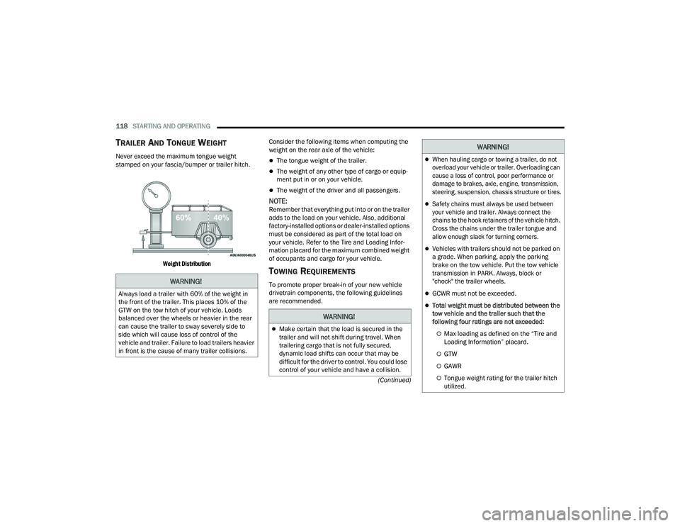
Never exceed the maximum tongue weight
stamped on your fascia/bumper or trailer hitch.
Weight Distribution
Consider the following items when computing the
weight on the rear axle of the vehicle:The tongue weight of the trailer.
The weight of any other type of cargo or equip
-
ment put in or on your vehicle.
The weight of the driver and all passengers.
NOTE:Remember that everything put into or on the trailer
adds to the load on your vehicle. Also, additional
factory-installed options or dealer-installed options
must be considered as part of the total load on
your vehicle. Refer to the Tire and Loading Infor -
mation placard for the maximum combined weight
of occupants and cargo for your vehicle.
TOWING REQUIREMENTS
To promote proper break-in of your new vehicle
drivetrain components, the following guidelines
are recommended.WARNING!
Always load a trailer with 60% of the weight in
the front of the trailer. This places 10% of the
GTW on the tow hitch of your vehicle. Loads
balanced over the wheels or heavier in the rear
can cause the trailer to sway severely side to
side which will cause loss of control of the
vehicle and trailer. Failure to load trailers heavier
in front is the cause of many trailer collisions.
WARNING!
Make certain that the load is secured in the
trailer and will not shift during travel. When
trailering cargo that is not fully secured,
dynamic load shifts can occur that may be
difficult for the driver to control. You could lose
control of your vehicle and have a collision.
When hauling cargo or towing a trailer, do not
overload your vehicle or trailer. Overloading can
cause a loss of control, poor performance or
damage to brakes, axle, engine, transmission,
steering, suspension, chassis structure or tires.
Safety chains must always be used between
your vehicle and trailer. Always connect the
chains to the hook retainers of the vehicle hitch.
Cross the chains under the trailer tongue and
allow enough slack for turning corners.
Vehicles with trailers should not be parked on
a grade. When parking, apply the parking
brake on the tow vehicle. Put the tow vehicle
transmission in PARK. Always, block or
"chock" the trailer wheels.
GCWR must not be exceeded.
Total weight must be distributed between the
tow vehicle and the trailer such that the
following four ratings are not exceeded :
Max loading as defined on the “Tire and
Loading Information” placard.
GTW
GAWR
Tongue weight rating for the trailer hitch
utilized.
WARNING!
22_LD_OM_EN_USC_t.book Page 118
Page 173 of 312
SAFETY171
(Continued)
ESC Operating Modes
Depending upon model and mode of operation, the
ESC system may have multiple operating modes.
"ESC On"
This is the normal operating mode for the ESC.
Whenever the vehicle is started, the ESC system
will be in this mode. This mode should be used for
most driving conditions. Alternate ESC modes
should only be used for specific reasons as noted
in the following paragraphs. "Partial Off"
This mode may be useful if the vehicle becomes
stuck. This mode may modify TCS and ESC
thresholds for activation, which allows for more
wheel spin than normally allowed.
To enter the “Partial Off” mode, momentarily push
the ESC OFF button and the ESC OFF Indicator
Light will illuminate. To turn the ESC on again,
momentarily push the ESC OFF button and the ESC
OFF Indicator Light will turn off.
NOTE:
For vehicles with multiple partial ESC modes,
the push and release of the button will toggle
the ESC modes. Multiple attempts may be
required to return to "ESC On" mode.
Trailer Sway Control (TSC) is disabled when the
ESC system is in the “Partial Off” mode.
If Equipped — "ESC Sport" and "ESC Track" are
ESC “Partial Off” mode(s).
“Full Off” – If Equipped
This mode is intended for off-highway or off-road
use only and should not be used on any public
roadways. In this mode, TCS and ESC features are
turned off. To enter the “Full Off” mode, push and
hold the ESC OFF button for five seconds while the
vehicle is stopped with the engine running. After
five seconds, a chime will sound, the ESC OFF
Indicator Light will illuminate, and the ESC OFF
message will display in the instrument cluster. To
turn ESC on again, momentarily push the ESC OFF
button.Vehicle modifications, or failure to properly
maintain your vehicle, may change the
handling characteristics of your vehicle, and
may negatively affect the performance of the
ESC system. Changes to the steering system,
suspension, braking system, tire type and size
or wheel size may adversely affect ESC perfor -
mance. Improperly inflated and unevenly worn
tires may also degrade ESC performance. Any
vehicle modification or poor vehicle mainte -
nance that reduces the effectiveness of the
ESC system can increase the risk of loss of
vehicle control, vehicle rollover, personal
injury and death.
WARNING!
WARNING!
When in “Partial Off” mode, the TCS functionality
of ESC, except for the limited slip feature
described in the TCS section, has been disabled
and the ESC OFF Indicator Light will be
illuminated. When in “Partial Off” mode, the
engine power reduction feature of Traction
Control System (TCS) is disabled, and the
enhanced vehicle stability offered by the ESC
system is reduced.
WARNING!
In the ESC “Full Off” mode, the engine torque
reduction and stability features are disabled.
Therefore, enhanced vehicle stability offered
by the ESC system is unavailable. In an emer -
gency evasive maneuver, the ESC system will
not engage to assist in maintaining stability.
ESC “Full Off” mode is intended for
off-highway or off-road use only.
6
22_LD_OM_EN_USC_t.book Page 171
Page 182 of 312
180SAFETY
NOTE:When filling warm tires, the tire pressure may need
to be increased up to an additional 4 psi (28 kPa)
above the recommended cold placard pressure in
order to turn the TPMS Warning Light off.
For example, your vehicle may have a
recommended cold (parked for more than three
hours) placard pressure of 30 psi (207 kPa). If the
ambient temperature is 68°F (20°C) and the
measured tire pressure is 27 psi (186 kPa), a
temperature drop to 20°F (-7°C) will decrease the
tire pressure to approximately 23 psi (158 kPa).
This tire pressure is sufficiently low enough to turn
on the TPMS Warning Light. Driving the vehicle
may cause the tire pressure to rise to
approximately 27 psi (186 kPa), but the TPMS
Warning Light will still be on. In this situation, the
TPMS Warning Light will turn off only after the tires
are inflated to the vehicle’s recommended cold
placard pressure value.NOTE:
The TPMS is not intended to replace normal tire
care and maintenance or to provide warning of
a tire failure or condition.
The TPMS should not be used as a tire pressure
gauge while adjusting your tire pressure.
Driving on a significantly underinflated tire
causes the tire to overheat and can lead to tire
failure. Underinflation also reduces fuel effi -
ciency and tire tread life, and may affect the
vehicle’s handling and stopping ability.
The TPMS is not a substitute for proper tire
maintenance, and it is the driver’s responsibility
to maintain correct tire pressure using an accu -
rate tire pressure gauge, even if underinflation
has not reached the level to trigger illumination
of the TPMS Warning Light.
Seasonal temperature changes will affect tire
pressure, and the TPMS will monitor the actual
tire pressure in the tire Ú page 296.
CAUTION!
The TPMS has been optimized for the original
equipment tires and wheels. TPMS pressures
and warning have been established for the tire
size equipped on your vehicle. Undesirable
system operation or sensor damage may
result when using replacement equipment
that is not of the same size, type, and/or style.
The TPMS sensor is not designed for use on
aftermarket wheels and may contribute to a
poor overall system performance or sensor
damage. Customers are encouraged to use
OEM wheels to ensure proper TPMS feature
operation.
Using aftermarket tire sealants may cause the
Tire Pressure Monitoring System (TPMS)
sensor to become inoperable. After using an
aftermarket tire sealant it is recommended
that you take your vehicle to your authorized
dealer to have your sensor function checked.
After inspecting or adjusting the tire pressure
always reinstall the valve stem cap. This will
prevent moisture and dirt from entering the
valve stem, which could damage the TPMS
sensor.
22_LD_OM_EN_USC_t.book Page 180
Page 266 of 312
264SERVICING AND MAINTENANCE
FRONT LOW/HIGH BEAM HEADLAMP —
MODELS WITH HIGH INTENSITY DISCHARGE
(HID) HEADLAMPS
The headlamps are a type of high voltage
discharge tube. High voltage can remain in the
circuit even with the headlamp switch off and the
key removed. Because of this, you should not
attempt to service a headlamp bulb yourself. If a
headlamp bulb fails, take your vehicle to an
authorized dealer for service.
NOTE:On vehicles equipped with HID headlamps, when
the headlamps are turned on, there is a blue hue
to the lights. This diminishes and becomes more
white after approximately 10 seconds, as the
system charges.
FRONT/REAR SIDE MARKER LAMP
The Side Markers use LED lamps that are not
serviceable separately. The Side Markers must be
replaced as an assembly, see an authorized
dealer.
FRONT FOG LAMP
The Front Fog Lamps use LED sources that are not
serviceable separately. The Front Fog Lamp must
be replaced as an assembly; see an authorized
dealer.
FRONT TURN SIGNAL LAMPS
The Front Park/Turn function is part of the
headlamp assembly and use LED lamps that are
not serviceable separately. The headlamps must
be replaced as an assembly, see an authorized
dealer.
BACKUP LAMPS
The Backup Lamps use LED sources that are not
serviceable separately. The backup lamps must be
replaced as an assembly; see an authorized
dealer.
LICENSE LAMP
The License Lamp uses an LED source that is not
serviceable separately. The License Lamp must be
replaced as an assembly; see an authorized
dealer.
CENTER HIGH MOUNTED STOP LAMP (CHMSL)
The CHMSL Lamp uses LED sources that are not
serviceable separately. The CHMSL Lamp must be
replaced as an assembly; see an authorized
dealer.
TIRES
TIRE SAFETY INFORMATION
Tire safety information will cover aspects of the
following information: Tire Markings, Tire
Identification Numbers, Tire Terminology and
Definitions, Tire Pressures, and Tire Loading.
WARNING!
A transient high voltage occurs at the bulb
sockets of HID headlamps when the headlamp
switch is turned ON. It may cause serious
electrical shock or electrocution if not serviced
properly. See an authorized dealer for service.
22_LD_OM_EN_USC_t.book Page 264
Page 275 of 312
SERVICING AND MAINTENANCE273
(Continued)
TIRES — GENERAL INFORMATION
Tire Pressure
Proper tire inflation pressure is essential to the
safe and satisfactory operation of your vehicle.
Four primary areas are affected by improper tire
pressure:
Safety
Fuel Economy
Tread Wear
Ride Comfort and Vehicle Stability
Safety Both underinflation and overinflation affect
thestability of the vehicle and can produce a
feeling of sluggish response or over
responsiveness in the steering.
NOTE:
Unequal tire pressures from side to side may
cause erratic and unpredictable steering
response.
Unequal tire pressure from side to side may
cause the vehicle to drift left or right.
Fuel Economy
Underinflated tires will increase tire rolling
resistance resulting in higher fuel consumption. Tread Wear
Improper cold tire inflation pressures can cause
abnormal wear patterns and reduced tread life,
resulting in the need for earlier tire replacement.
Ride Comfort And Vehicle Stability
Proper tire inflation contributes to a comfortable
ride. Overinflation produces a jarring and
uncomfortable ride.
Tire Inflation Pressures
The proper cold tire inflation pressure is listed on
the driver's side B-pillar or rear edge of the driver's
side door.
At least once a month:
Check and adjust tire pressure with a good
quality pocket-type pressure gauge. Do not
make a visual judgement when determining
proper inflation. Tires may look properly inflated
even when they are underinflated.
Inspect tires for signs of tire wear or visible
damage.
WARNING!
Improperly inflated tires are dangerous and
can cause collisions.
Underinflation increases tire flexing and can
result in overheating and tire failure.
Overinflation reduces a tire's ability to cushion
shock. Objects on the road and chuckholes
can cause damage that result in tire failure.
Overinflated or underinflated tires can affect
vehicle handling and can fail suddenly,
resulting in loss of vehicle control.
Unequal tire pressures can cause steering
problems. You could lose control of your
vehicle.
Unequal tire pressures from one side of the
vehicle to the other can cause the vehicle to
drift to the right or left.
Always drive with each tire inflated to the
recommended cold tire inflation p ressure.
WARNING!
CAUTION!
After inspecting or adjusting the tire pressure,
always reinstall the valve stem cap. This will
prevent moisture and dirt from entering the
valve stem, which could damage the valve stem.
8
22_LD_OM_EN_USC_t.book Page 273
Page 276 of 312
274SERVICING AND MAINTENANCE
Inflation pressures specified on the placard are
always “cold tire inflation pressure”. Cold tire
inflation pressure is defined as the tire pressure
after the vehicle has not been driven for at least
three hours, or driven less than 1 mile (1.6 km)
after sitting for a minimum of three hours. The cold
tire inflation pressure must not exceed the
maximum inflation pressure molded into the tire
sidewall.
Check tire pressures more often if subject to a
wide range of outdoor temperatures, as tire
pressures vary with temperature changes.
Tire pressures change by approximately 1 psi
(7 kPa) per 12°F (7°C) of air temperature change.
Keep this in mind when checking tire pressure
inside a garage, especially in the Winter.
Example: If garage temperature = 68°F (20°C)
and the outside temperature = 32°F (0°C) then
the cold tire inflation pressure should be increased
by 3 psi (21 kPa), which equals 1 psi (7 kPa) for
every 12°F (7°C) for this outside temperature
condition.
Tire pressure may increase from 2 to 6 psi (13 to
40 kPa) during operation. DO NOT reduce this
normal pressure build up or your tire pressure will
be too low.
Tire Pressures For High Speed Operation
The manufacturer advocates driving at safe
speeds and within posted speed limits. Where
speed limits or conditions are such that the vehicle
can be driven at high speeds, maintaining correct
tire inflation pressure is very important. Increased
tire pressure and reduced vehicle loading may be
required for high-speed vehicle operation. Refer to
an authorized tire dealer or original equipment
vehicle dealer for recommended safe operating
speeds, loading and cold tire inflation pressures.
Radial Ply Tires
Tire Repair
If your tire becomes damaged, it may be repaired if
it meets the following criteria:
The tire has not been driven on when flat.
The damage is only on the tread section of your
tire (sidewall damage is not repairable).
The puncture is no greater than a ¼ of an inch
(6 mm).
Consult an authorized tire dealer for tire repairs
and additional information.
Damaged Run Flat tires, or Run Flat tires that have
experienced a loss of pressure should be replaced
immediately with another Run Flat tire of identical
size and service description (Load Index and
Speed Symbol). Replace the tire pressure sensor
as well as it is not designed to be reused.
WARNING!
High speed driving with your vehicle under
maximum load is dangerous. The added strain
on your tires could cause them to fail. You could
have a serious collision. Do not drive a vehicle
loaded to the maximum capacity at continuous
speeds above 75 mph (120 km/h).
WARNING!
Combining radial ply tires with other types of
tires on your vehicle will cause your vehicle to
handle poorly. The instability could cause a
collision. Always use radial ply tires in sets of
four. Never combine them with other types of
tires.
22_LD_OM_EN_USC_t.book Page 274