warning light DODGE CHARGER SRT 2018 Owners Manual
[x] Cancel search | Manufacturer: DODGE, Model Year: 2018, Model line: CHARGER SRT, Model: DODGE CHARGER SRT 2018Pages: 490, PDF Size: 5.08 MB
Page 7 of 490
HOW TO USE THIS MANUAL
Essential Information
Consult the Table of Contents to determine which section
contains the information you desire.
Since the specification of your vehicle depends on the items
of equipment ordered, certain descriptions and illustra-
tions may differ from your vehicle’s equipment.
The detailed index at the back of this Owner’s Manual
contains a complete listing of all subjects.
Symbols
Some vehicle components have colored labels whose sym-
bols indicate precautions to be observed when using this
component. Refer to “Warning Lights and Messages” in
“Getting To Know Your Instrument Panel” for further
information on the symbols used in your vehicle.
WARNINGS AND CAUTIONS
This Owner ’s Manual containsWARNINGSagainst operat-
ing procedures that could result in a collision, bodily injury
and/or death. It also contains CAUTIONSagainst proce-
dures that could result in damage to your vehicle. If you do
not read this entire Owner ’s Manual, you may miss impor-
tant information. Observe all Warnings and Cautions.
VEHICLE MODIFICATIONS/ALTERATIONS
WARNING!
Any modifications or alterations to this vehicle could
seriously affect its roadworthiness and safety and may
lead to a collision resulting in serious injury or death.
WARNING!
To prevent SERIOUS INJURY or DEATH when using
“Track-Use” parts and equipment:
• NEVER use any “Track-Use” equipment on public
roads. FCA US LLC does not authorize the use of
“Track-Use” equipment on public roads.
• The intended use of “Track-Use” parts is for race
vehicles on race tracks. To help ensure the safety of
the race driver, engineers should supervise the instal-
lation of “Track-Use” parts.
• FCA US LLC does not authorize the installation or
use of any part noted as “Track-Use” on any new
vehicle prior to its first retail sale.
1
INTRODUCTION 5
Page 26 of 490
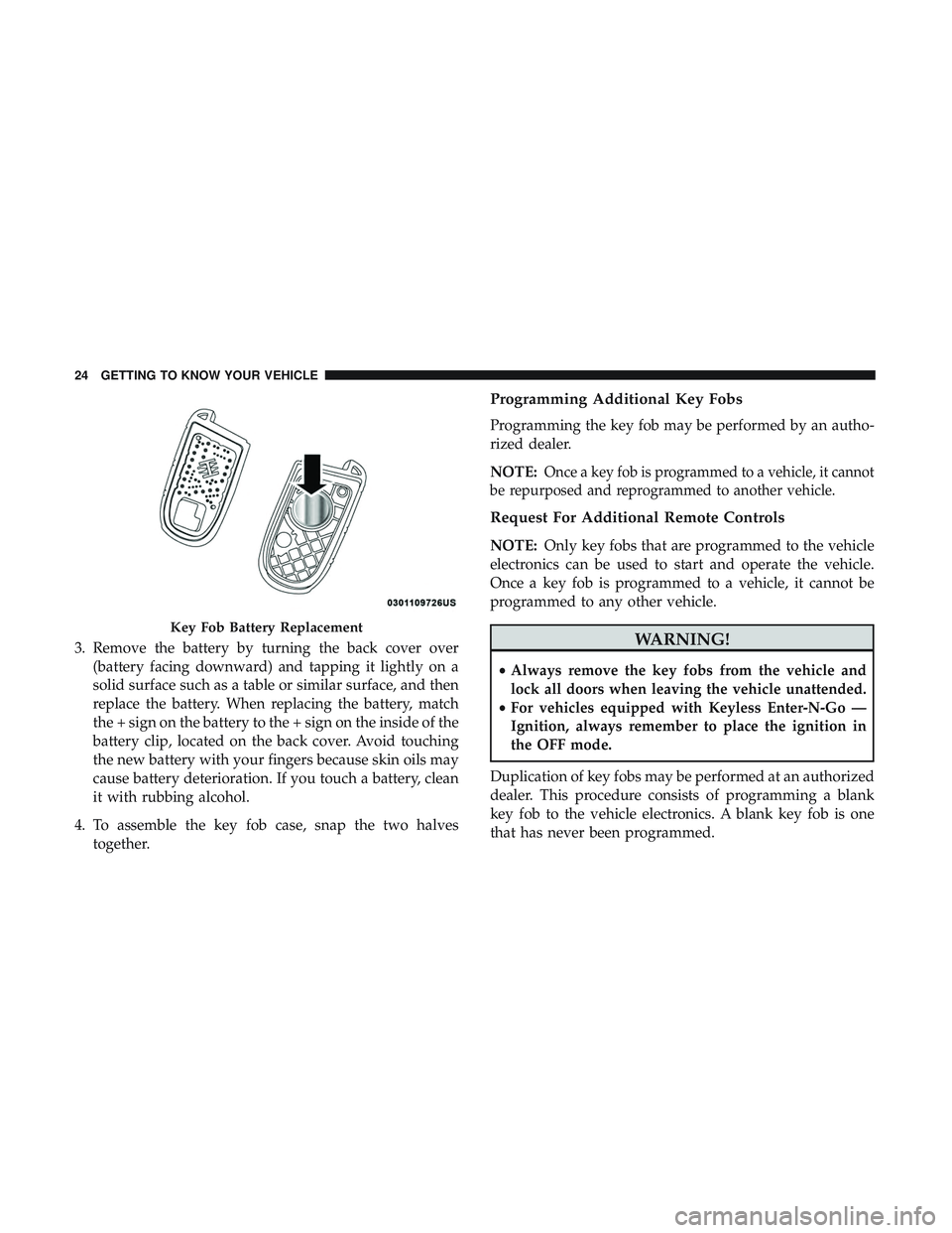
3. Remove the battery by turning the back cover over(battery facing downward) and tapping it lightly on a
solid surface such as a table or similar surface, and then
replace the battery. When replacing the battery, match
the + sign on the battery to the + sign on the inside of the
battery clip, located on the back cover. Avoid touching
the new battery with your fingers because skin oils may
cause battery deterioration. If you touch a battery, clean
it with rubbing alcohol.
4. To assemble the key fob case, snap the two halves together.
Programming Additional Key Fobs
Programming the key fob may be performed by an autho-
rized dealer.
NOTE:
Once a key fob is programmed to a vehicle, it cannot
be repurposed and reprogrammed to another vehicle.
Request For Additional Remote Controls
NOTE: Only key fobs that are programmed to the vehicle
electronics can be used to start and operate the vehicle.
Once a key fob is programmed to a vehicle, it cannot be
programmed to any other vehicle.
WARNING!
• Always remove the key fobs from the vehicle and
lock all doors when leaving the vehicle unattended.
• For vehicles equipped with Keyless Enter-N-Go —
Ignition, always remember to place the ignition in
the OFF mode.
Duplication of key fobs may be performed at an authorized
dealer. This procedure consists of programming a blank
key fob to the vehicle electronics. A blank key fob is one
that has never been programmed.
Key Fob Battery Replacement
24 GETTING TO KNOW YOUR VEHICLE
Page 31 of 490
•Hazard switch off
• Brake switch inactive (brake pedal not pushed)
• Battery at an acceptable charge level
• Check engine light shall not be present
• PANIC button not pushed
• System not disabled from previous remote start event
• Vehicle alarm system indicator flashing
• Ignition in STOP/OFF position
• Fuel level meets minimum requirement
• Vehicle Security Alarm is not signaling an intrusion
WARNING!
•Do not start or run an engine in a closed garage or
confined area. Exhaust gas contains Carbon Monox-
ide (CO) which is odorless and colorless. Carbon
Monoxide is poisonous and can cause serious injury
or death when inhaled.
• Keep key fobs away from children. Operation of the
Remote Start System, windows, door locks or other
controls could cause serious injury or death.
Remote Start Abort Message On The Instrument
Cluster Display — If Equipped
The following messages will display in the instrument
cluster display if the vehicle fails to remote start or exits
remote start prematurely:
• Remote Start Aborted — Door Open
• Remote Start Aborted — Hood Open
• Remote Start Aborted — Fuel Low
• Remote Start Aborted — Trunk Open
• Remote Start Disabled — Start Vehicle To Reset
The message will stay active until the ignition is turned to
the ON/RUN position.
To Enter Remote Start Mode
Push and release the remote start button on the key fob
twice within five seconds. The vehicle doors will lock, the
parking lights will flash, and the horn will chirp twice (if
programmed). Then, the engine will start, and the vehicle
will remain in the Remote Start mode for a 15-minute cycle.
3
GETTING TO KNOW YOUR VEHICLE 29
Page 33 of 490
To Cancel Remote Start
Remote Starting will also cancel if any of the following
occur:
•The engine stalls or engine speed exceeds 2500 rpm.
• Any engine warning lights come on.
• Low Fuel Light turns on.
• The hood is opened.
• The hazard switch is pushed.
• The gear selector is moved out of PARK.
• The brake pedal is pushed.
Remote Start Comfort Systems — If Equipped
When remote start is activated, the heated steering wheel
and driver heated seat features will automatically turn on
in cold weather. In warm weather, the driver vented seat
feature will automatically turn on when the remote start is
activated. These features will stay on through the duration
of remote start or until the ignition switch is cycled to the
ON/RUN position.
General Information
The following regulatory statement applies to all radio
frequency (RF) devices equipped in this vehicle:
This device complies with Part 15 of the FCC Rules and
with Industry Canada license-exempt RSS standard(s).
Operation is subject to the following two conditions:
1. This device may not cause harmful interference, and
2. This device must accept any interference received, in-
cluding interference that may cause undesired opera-
tion.
NOTE: Changes or modifications not expressly approved
by the party responsible for compliance could void the
user ’s authority to operate the equipment.
SENTRY KEY
The Sentry Key Immobilizer System prevents unauthor-
ized vehicle operation by disabling the engine. The system
does not need to be armed or activated. Operation is
automatic, regardless of whether the vehicle is locked or
unlocked.
3
GETTING TO KNOW YOUR VEHICLE 31
Page 37 of 490
Rearming Of The System
If something triggers the alarm, and no action is taken to
disarm it, the vehicle security alarm will turn the horn off
after 29 seconds, five seconds between cycles, up to eight
cycles if the trigger remains active and the vehicle security
alarm will rearm itself.
Tamper Alert
If something has triggered the vehicle security alarm in
your absence, the horn will sound three times and the
exterior lights will blink three times when you disarm the
vehicle security alarm. Check the vehicle for tampering.
DOORS
Manual Door Locks
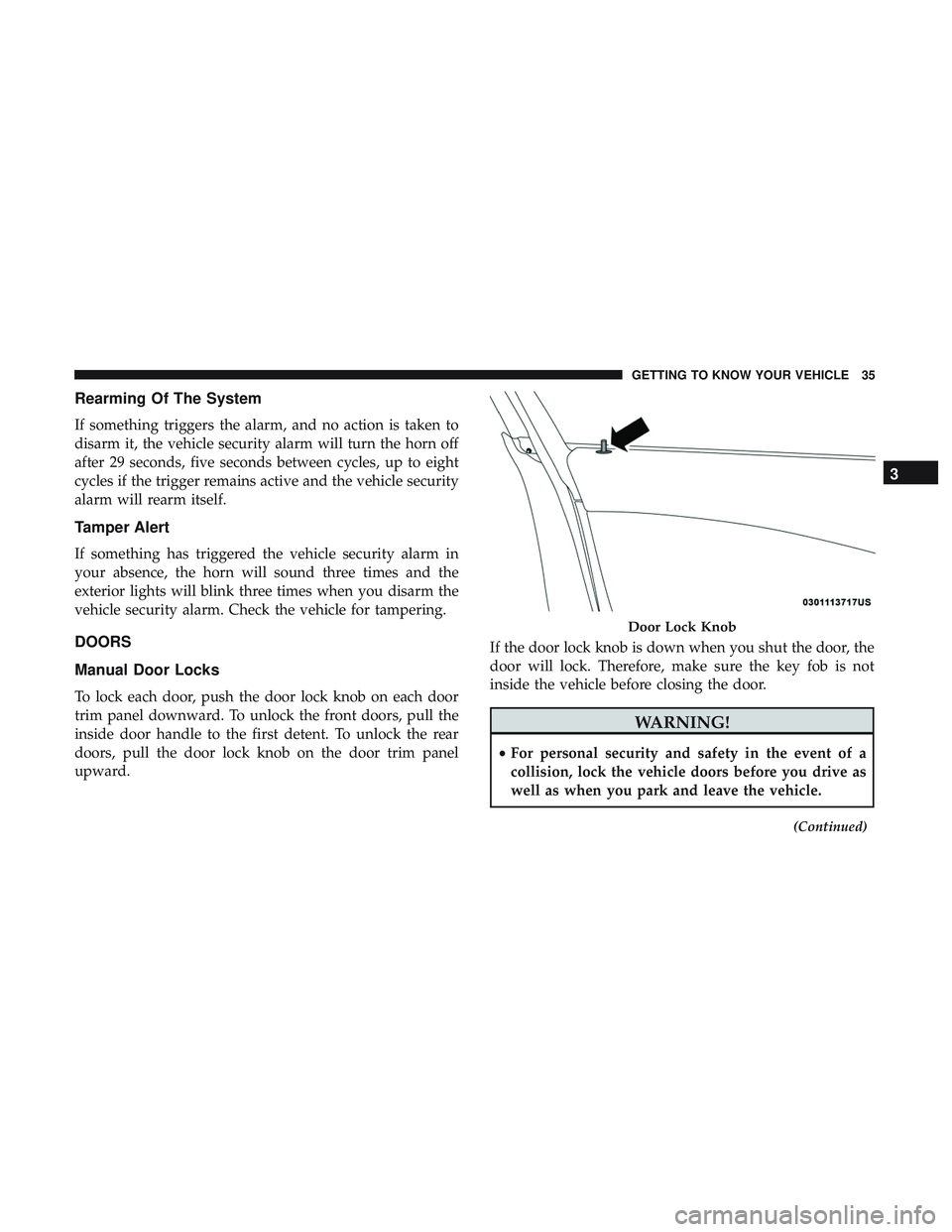
To lock each door, push the door lock knob on each door
trim panel downward. To unlock the front doors, pull the
inside door handle to the first detent. To unlock the rear
doors, pull the door lock knob on the door trim panel
upward.If the door lock knob is down when you shut the door, the
door will lock. Therefore, make sure the key fob is not
inside the vehicle before closing the door.
WARNING!
•
For personal security and safety in the event of a
collision, lock the vehicle doors before you drive as
well as when you park and leave the vehicle.
(Continued)
Door Lock Knob
3
GETTING TO KNOW YOUR VEHICLE 35
Page 51 of 490
WARNING!(Continued)
at low temperatures, especially if used for long
periods of time.
• Do not place anything on the seat or seatback that
insulates against heat, such as a blanket or cushion.
This may cause the seat heater to overheat. Sitting in
a seat that has been overheated could cause serious
burns due to the increased surface temperature of the
seat.
Rear Heated Seats
On some models, the two outboard seats are equipped
with heated seats. The heated seat switches for these seats
are located on the rear of the center console. There are two
heated seat switches
that allow the rear passengers to
operate the seats independently.
You can choose from HI, LO, or off heat settings. The
indicator lights in each switch indicate the level of heat in
use. Two indicator lights will illuminate for HI, one for LO,
and none for off.
• Push the heated seat button
once to select HI-level
heating.
• Push the heated seat buttona second time to select
LO-level heating.
• Push the heated seat buttona third time to turn the
heating elements off.
NOTE:
• Once a heat setting is selected, heat will be felt within
two to five minutes.
• The engine must be running for the heated seats to
operate.
If the HI-level setting is selected, the system will automati-
cally switch to LO-level after approximately 60 minutes of
continuous operation. At that time, the number of illumi-
nated LEDs changes from two to one, indicating the
change. The LO-level setting will turn off automatically
after approximately 45 minutes.
Front Ventilated Seats — If Equipped
Located in the seat cushion and seat back are fans that
draw the air from the passenger compartment and move
air through fine perforations in the seat cover to help keep
the driver and front passenger cooler in higher ambient
temperatures. The fans operate at two speeds, HI and LO.
3
GETTING TO KNOW YOUR VEHICLE 49
Page 58 of 490
•Press the heated steering wheel buttona second time
to turn the heating element off.
NOTE: The engine must be running for the heated steering
wheel to operate.
Vehicles Equipped With Remote Start
On models that are equipped with remote start, the heated
steering wheel can be programmed to come on during a
remote start through the Uconnect system. Refer to
“Uconnect Settings” in “Multimedia” for further informa-
tion.
WARNING!
• Persons who are unable to feel pain to the skin
because of advanced age, chronic illness, diabetes,
spinal cord injury, medication, alcohol use, exhaus-
tion, or other physical conditions must exercise care
when using the steering wheel heater. It may cause
burns even at low temperatures, especially if used
for long periods.
• Do not place anything on the steering wheel that
insulates against heat, such as a blanket or steering
wheel covers of any type and material. This may
cause the steering wheel heater to overheat.
MIRRORS
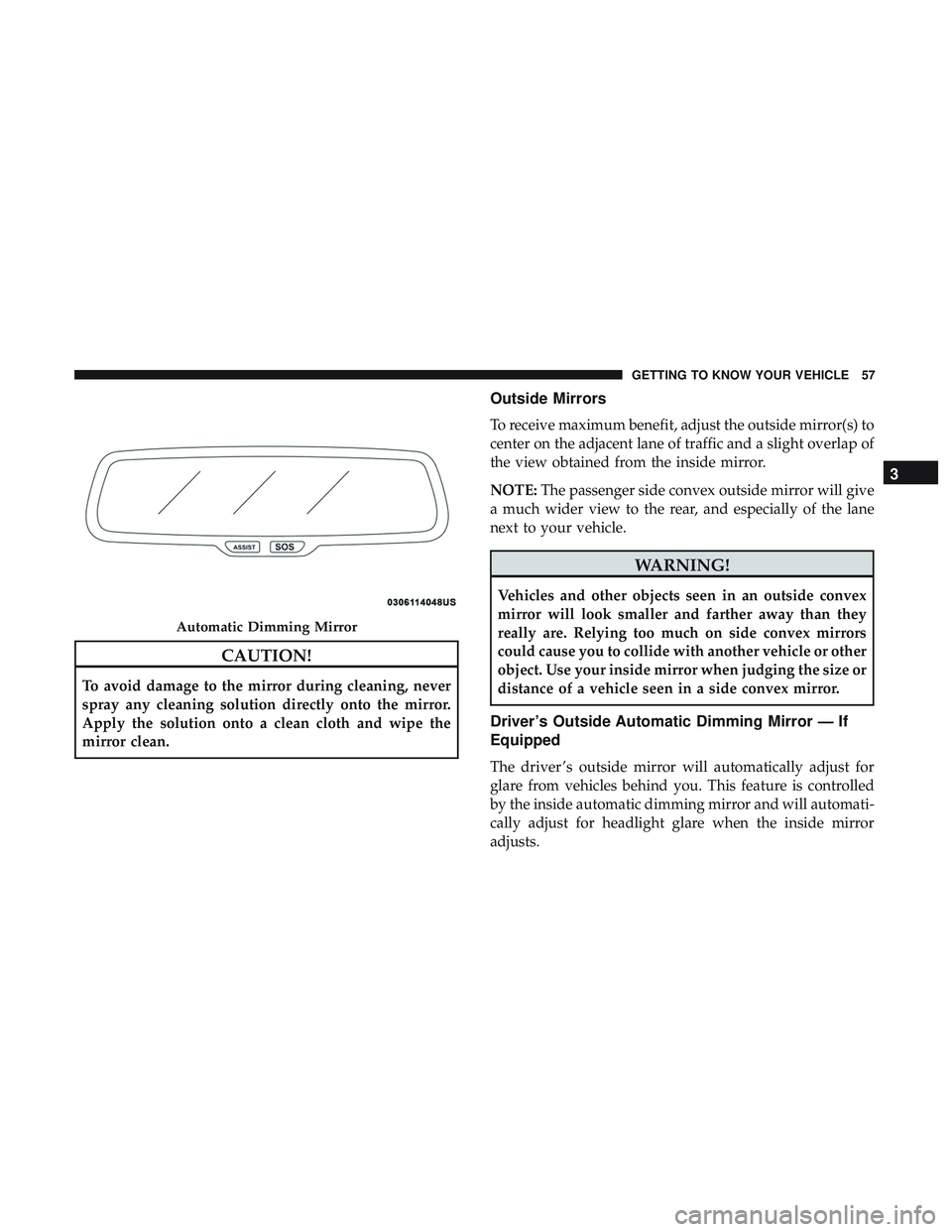
Automatic Dimming Mirror — If Equipped
The mirror head can be adjusted up, down, left, and right
for various drivers. The mirror should be adjusted to center
on the view through the rear window.
This mirror automatically adjusts for headlight glare from
vehicles behind you.
NOTE: The Automatic Dimming feature is disabled when
the vehicle is in REVERSE to improve rear view viewing.
The Automatic Dimming feature can be turned on or off
through the touchscreen.
• Press the mirror dimmer button once to turn the feature
on.
• Press the mirror dimmer button a second time to turn
the feature off.
56 GETTING TO KNOW YOUR VEHICLE
Page 59 of 490
CAUTION!
To avoid damage to the mirror during cleaning, never
spray any cleaning solution directly onto the mirror.
Apply the solution onto a clean cloth and wipe the
mirror clean.
Outside Mirrors
To receive maximum benefit, adjust the outside mirror(s) to
center on the adjacent lane of traffic and a slight overlap of
the view obtained from the inside mirror.
NOTE:The passenger side convex outside mirror will give
a much wider view to the rear, and especially of the lane
next to your vehicle.
WARNING!
Vehicles and other objects seen in an outside convex
mirror will look smaller and farther away than they
really are. Relying too much on side convex mirrors
could cause you to collide with another vehicle or other
object. Use your inside mirror when judging the size or
distance of a vehicle seen in a side convex mirror.
Driver’s Outside Automatic Dimming Mirror — If
Equipped
The driver ’s outside mirror will automatically adjust for
glare from vehicles behind you. This feature is controlled
by the inside automatic dimming mirror and will automati-
cally adjust for headlight glare when the inside mirror
adjusts.
Automatic Dimming Mirror
3
GETTING TO KNOW YOUR VEHICLE 57
Page 92 of 490
WARNING!
•Be certain that the seatback is securely locked into
position. If the seatback is not securely locked into
position, the seat will not provide the proper stabil-
ity for child seats and/or passengers. An improperly
latched seat could cause serious injury.
• The cargo area in the rear of the vehicle (with the rear
seatbacks in the locked-up or folded down position)
should not be used as a play area by children when
the vehicle is in motion. They could be seriously
injured in a collision. Children should be seated and
using the proper restraint system.
• To help protect against personal injury, passengers
should not be seated in the rear cargo area. The rear
cargo space is intended for load carrying purposes
only, not for passengers, who should sit in seats and
use seat belts.
The weight and position of cargo and passengers can
change the vehicle center of gravity and vehicle han-
dling. To avoid loss of control resulting in personal
injury, follow these guidelines for loading your vehicle:
•Always place cargo evenly on the cargo floor. Put
heavier objects as low and as far forward as possible.
(Continued)
WARNING! (Continued)
•Place as much cargo as possible in front of the rear
axle. Too much weight or improperly placed weight
over or behind the rear axle can cause the rear of the
vehicle to sway.
• Do not pile luggage or cargo higher than the top of
the seatback. This could impair visibility or become
a dangerous projectile in a sudden stop or collision.
GARAGE DOOR OPENER — IF EQUIPPED
HomeLink replaces up to three hand-held transmitters that
operate devices such as garage door openers, motorized
gates, lighting or home security systems. The HomeLink
unit is powered by your vehicle’s battery.
The HomeLink buttons, located on either the overhead
console, headliner or sunvisor, designate the three different
HomeLink channels. The HomeLink indicator is located
above the center button.
90 GETTING TO KNOW YOUR VEHICLE
Page 105 of 490
WARNING!
To avoid serious injury or death:
•Only devices designed for use in this type of outlet
should be inserted into any 12 Volt outlet.
• Do not touch with wet hands.
• Close the lid when not in use and while driving the
vehicle.
• If this outlet is mishandled, it may cause an electric
shock and failure.
CAUTION!
•Many accessories that can be plugged in draw power
from the vehicle’s battery even when not in use (i.e.,
cellular phones, etc.). Eventually, if plugged in long
enough, the vehicle’s battery will discharge suffi-
ciently to degrade battery life and/or prevent the
engine from starting.
• Accessories that draw higher power (i.e., coolers,
vacuum cleaners, lights, etc.) will degrade the battery
even more quickly. Only use these intermittently and
with greater caution.
(Continued)
CAUTION! (Continued)
•After the use of high power draw accessories or long
periods of the vehicle not being started (with acces-
sories still plugged in), the vehicle must be driven a
sufficient length of time to allow the alternator to
recharge the vehicle’s battery.
• Power outlets are designed for accessory plugs only.
Do not hang any type of accessory or accessory
bracket from the plug. Improper use of the power
outlet can cause damage.
3
GETTING TO KNOW YOUR VEHICLE 103