capacity DODGE CHARGER SRT 2019 Owners Manual
[x] Cancel search | Manufacturer: DODGE, Model Year: 2019, Model line: CHARGER SRT, Model: DODGE CHARGER SRT 2019Pages: 496, PDF Size: 5.32 MB
Page 125 of 496
If the light remains on when the parking brake has been
disengaged, and the fluid level is at the full mark on the
master cylinder reservoir, it indicates a possible brake
hydraulic system malfunction or that a problem with the
Brake Booster has been detected by the Anti-Lock Brake
System (ABS) / Electronic Stability Control (ESC) system.
In this case, the light will remain on until the condition has
been corrected. If the problem is related to the brake
booster, the ABS pump will run when applying the brake,
and a brake pedal pulsation may be felt during each stop.
The dual brake system provides a reserve braking capacity
in the event of a failure to a portion of the hydraulic
system. A leak in either half of the dual brake system is
indicated by the Brake Warning Light, which will turn on
when the brake fluid level in the master cylinder has
dropped below a specified level.
The light will remain on until the cause is corrected.
NOTE:The light may flash momentarily during sharp
cornering maneuvers, which change fluid level conditions.
The vehicle should have service performed, and the brake
fluid level checked.
If brake failure is indicated, immediate repair is necessary.WARNING!
Driving a vehicle with the red brake light on is
dangerous. Part of the brake system may have failed. It
will take longer to stop the vehicle. You could have a
collision. Have the vehicle checked immediately.
Vehicles equipped with the Anti-Lock Brake System (ABS)
are also equipped with Electronic Brake Force Distribution
(EBD). In the event of an EBD failure, the Brake Warning
Light will turn on along with the ABS Light. Immediate
repair to the ABS system is required.
Operation of the Brake Warning Light can be checked by
turning the ignition switch from the OFF position to the
ON/RUN position. The light should illuminate for ap-
proximately two seconds. The light should then turn off
unless the parking brake is applied or a brake fault is
detected. If the light does not illuminate, have the light
inspected by an authorized dealer.
The light also will turn on when the parking brake is
applied with the ignition switch in the ON/RUN position.
NOTE: This light shows only that the parking brake is
applied. It does not show the degree of brake application.
4
GETTING TO KNOW YOUR INSTRUMENT PANEL 123
Page 234 of 496
Launch control will be active until the vehicle reaches
62 mph (100 km/h), at which point the ESC system will
return to its current ESC mode.
Launch control will abort before launch completion, dis-
play “Launch Aborted” in the cluster under any of the
following conditions:
•The accelerator pedal is released during launch. ESC
system continues in ESC Full ON.
• The ESC system detects that the vehicle is no longer
moving in a straight line.
• The “ESC OFF” button is pushed to change the system
to another mode.
NOTE: After launch control has been aborted, ESC will
return to its current ESC mode.
CAUTION!
Do not attempt to shift when the drive wheels are
spinning and do not have traction. Damage to the
transmission may occur.
Guidelines For Track Use
NOTE: Because of the extreme conditions encountered
during track use, any damage or wear associated with
track use may not be covered by warranty.
• If your SRT vehicle is equipped with Drive Modes, they
will alter the vehicle’s performance in various driving
situations. It is recommended that your vehicle operates
in SPORT or TRACK modes during the track event.
• Prior to each track event/day, verify all fluids are at the
correct levels. Refer to “Fluid Capacities” in “Technical
Specifications” for further information.
• Prior to each track event, verify the front and rear brake
pads have more than ½ pad thickness remaining. If the
brake pads require changing, please burnish prior to
track outing at full pace.
NOTE: Use of DOT 4 brake fluid is suggested for extended
track usage due to increased thermal capacity.
• At the conclusion of each track event, it is recommended
that a brake bleed procedure is performed to maintain
the pedal feel and stopping capability of your Brembo
High Performance brake system.
232 STARTING AND OPERATING
Page 236 of 496
4. Allow vehicle to sit and cool in the paddock for at least30 min. If an infrared thermal gun is available, allow
rotors to cool to 200°F (93.3°C) before going back out.
5. There should be a thin ash layer when inspecting the pads installed in the caliper. Having the ash layer go
more than half the thickness of the pad material indi-
cates too aggressive of a burnish.
6. Sometimes, a second burnish session is required. If the pads start smelling in the next track session, reduce
speed and braking decel to burnish targets and follow
steps two through four.
7. New pads installed on old rotors still need to be burnished. New rotors installed with old pads should be
burnished at the track or street driven for 300 city miles
to develop an adequate lining transfer layer on the rotor
surface prior to track use.
8. Rotors that pulsate during track use should be replaced. Resurfacing of the rotors is not recommended, as it
removes mass from the rotor, reducing its thermal
capacity. Resurfacing also thins the rotor cheek, making
it less robust and increasing the likelihood of pulsation
in further track use.HYDRAULIC POWER STEERING — IF EQUIPPED
The hydraulic power steering system is sport tuned and
will give you good vehicle response and increased ease of
maneuverability in tight spaces. The system will provide
mechanical steering capability if power assist is lost.
If for some reason the power assist is interrupted, it will
still be possible to steer your vehicle. Under these condi-
tions, you will observe a substantial increase in steering
effort, especially at very low vehicle speeds and during
parking maneuvers.
NOTE:
•Increased noise levels at the end of the steering wheel
travel are considered normal and do not indicate that
there is a problem with the power steering system.
• Upon initial start-up in cold weather, the power steering
pump may make noise for a short amount of time. This
is due to the cold, thick fluid in the steering system. This
noise should be considered normal, and it does not in
any way damage the steering system.
234 STARTING AND OPERATING
Page 250 of 496
To increase the distance setting, push the Distance Setting
— Increase button and release. Each time the button is
pushed, the distance setting increases by one bar (longer).
To decrease the distance setting, push the Distance Setting
— Decrease button and release. Each time the button is
pushed, the distance setting decreases by one bar (shorter).
If there is no vehicle ahead, the vehicle will maintain the set
speed. If a slower moving vehicle is detected in the same lane,
the instrument cluster displays the “Sensed Vehicle Indicator”
icon, and the system adjusts vehicle speed automatically to
maintain the distance setting, regardless of the set speed.
The vehicle will then maintain the set distance until:
•The vehicle ahead accelerates to a speed above the set
speed.
• The vehicle ahead moves out of your lane or view of the
sensor.
• The distance setting is changed.
• The system disengages. (Refer to the information on
ACC Activation).
The maximum braking applied by ACC is limited; how-
ever, the driver can always apply the brakes manually, if
necessary.
NOTE: The brake lights will illuminate whenever the ACC
system applies the brakes.
A Proximity Warning will alert the driver if ACC predicts
that its maximum braking level is not sufficient to maintain
the set distance. If this occurs, a visual alert “BRAKE” will
flash in the instrument cluster display and a chime will
sound while ACC continues to apply its maximum braking
capacity.
Distance Setting 1 Bar (Short)
248 STARTING AND OPERATING
Page 277 of 496
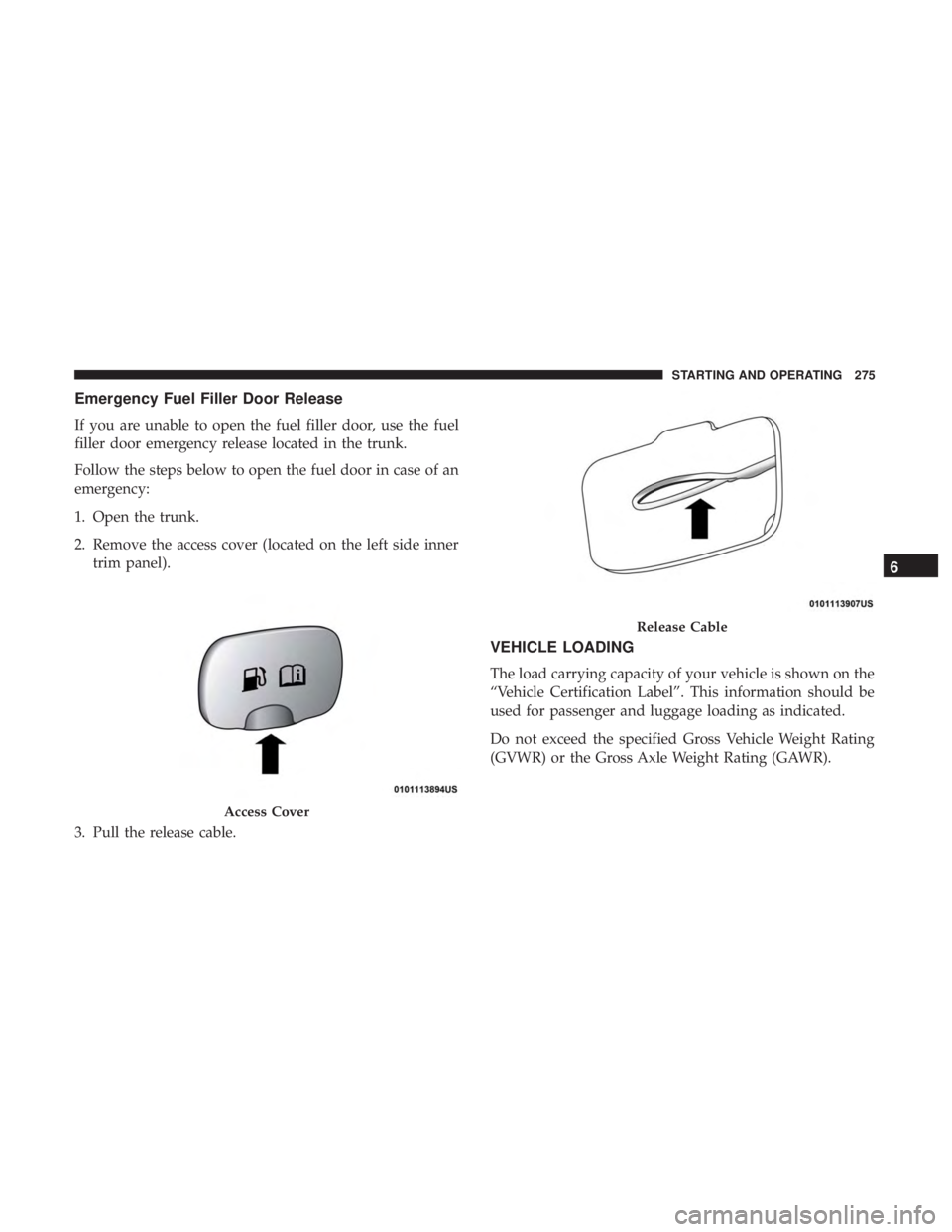
Emergency Fuel Filler Door Release
If you are unable to open the fuel filler door, use the fuel
filler door emergency release located in the trunk.
Follow the steps below to open the fuel door in case of an
emergency:
1. Open the trunk.
2. Remove the access cover (located on the left side innertrim panel).
3. Pull the release cable.
VEHICLE LOADING
The load carrying capacity of your vehicle is shown on the
“Vehicle Certification Label”. This information should be
used for passenger and luggage loading as indicated.
Do not exceed the specified Gross Vehicle Weight Rating
(GVWR) or the Gross Axle Weight Rating (GAWR).
Access Cover
Release Cable
6
STARTING AND OPERATING 275
Page 278 of 496
Vehicle Certification Label
Your vehicle has a Vehicle Certification Label affixed to the
drivers side B-Pillar or the rear of the driver ’s door.
The label contains the following information:
•Name of manufacturer
• Month and year of manufacture
• Gross Vehicle Weight Rating (GVWR)
• Gross Axle Weight Rating (GAWR) front
• Gross Axle Weight Rating (GAWR) rear
• Vehicle Identification Number (VIN)
• Type of vehicle
• Month, Day, and Hour of manufacture (MDH)
The bar code allows a computer scanner to read the VIN.
Gross Vehicle Weight Rating (GVWR)
The GVWR is the total allowable weight of your vehicle.
This includes driver, passengers, and cargo. The total load
must be limited so that you do not exceed the GVWR.
Gross Axle Weight Rating (GAWR)
The GAWR is the maximum capacity of the front and rear
axles. Distribute the load over the front and rear axles
evenly. Make sure that you do not exceed either front or
rear GAWR.
WARNING!
Because the front wheels steer the vehicle, it is impor-
tant that you do not exceed the maximum front or rear
GAWR. A dangerous driving condition can result if
either rating is exceeded. You could lose control of the
vehicle and have a collision.
Overloading
The load carrying components (axle, springs, tires, wheels,
etc.) of your vehicle will provide satisfactory service as
long as you do not exceed the GVWR and the front and
rear GAWR.
The best way to figure out the total weight of your vehicle
is to weigh it when it is fully loaded and ready for
operation. Weigh it on a commercial scale to ensure that it
is not over the GVWR.
276 STARTING AND OPERATING
Page 355 of 496
WARNING!
Riding the brakes can lead to brake failure and possi-
bly a collision. Driving with your foot resting or riding
on the brake pedal can result in abnormally high brake
temperatures, excessive lining wear, and possible
brake damage. You would not have your full braking
capacity in an emergency.
Fluid Level Check — Brake Master Cylinder
Check the fluid level in the master cylinder immediately if
the brake system warning light indicates system failure.
Check the fluid level in the master cylinder when perform-
ing underhood services.
Clean the top of the master cylinder area before removing
the cap. Add fluid to bring the level up to the top of the
“FULL” mark on the side of the master cylinder reservoir.
Overfilling of fluid is not recommended because it may
cause leaking in the system.Add enough fluid to bring the level up to the requirements
described on the brake fluid reservoir. With disc brakes,
fluid level can be expected to fall as the brake pads wear.
However, low fluid level may be caused by a leak and a
checkup may be needed.
Use only brake fluid that has been recommended by the
manufacturer, and has been kept in a tightly closed con-
tainer to avoid contamination from foreign matter or
moisture.
Refer to “Fluids And Lubricants” in “Technical Specifica-
tions” for further information.
WARNING!
•
Use only manufacturer’s recommended brake fluid.
Refer to “Fluids And Lubricants” in “Technical
Specifications” for further information. Using the
wrong type of brake fluid can severely damage your
brake system and/or impair its performance. The
proper type of brake fluid for your vehicle is also
identified on the original factory installed hydraulic
master cylinder reservoir.
(Continued)
8
SERVICING AND MAINTENANCE 353
Page 362 of 496
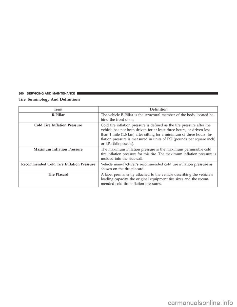
Tire Terminology And Definitions
TermDefinition
B-Pillar The vehicle B-Pillar is the structural member of the body located be-
hind the front door.
Cold Tire Inflation Pressure Cold tire inflation pressure is defined as the tire pressure after the
vehicle has not been driven for at least three hours, or driven less
than 1 mile (1.6 km) after sitting for a minimum of three hours. In-
flation pressure is measured in units of PSI (pounds per square inch)
or kPa (kilopascals).
Maximum Inflation Pressure The maximum inflation pressure is the maximum permissible cold
tire inflation pressure for this tire. The maximum inflation pressure is
molded into the sidewall.
Recommended Cold Tire Inflation Pressure Vehicle manufacturer’s recommended cold tire inflation pressure as
shown on the tire placard.
Tire Placard A label permanently attached to the vehicle describing the vehicle’s
loading capacity, the original equipment tire sizes and the recom-
mended cold tire inflation pressures.
360 SERVICING AND MAINTENANCE
Page 364 of 496
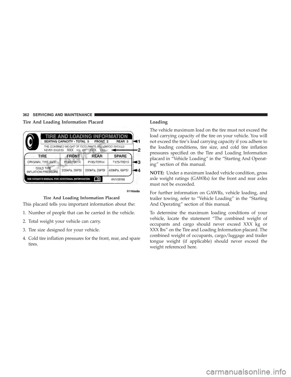
Tire And Loading Information Placard
This placard tells you important information about the:
1. Number of people that can be carried in the vehicle.
2. Total weight your vehicle can carry.
3. Tire size designed for your vehicle.
4. Cold tire inflation pressures for the front, rear, and sparetires.Loading
The vehicle maximum load on the tire must not exceed the
load carrying capacity of the tire on your vehicle. You will
not exceed the tire’s load carrying capacity if you adhere to
the loading conditions, tire size, and cold tire inflation
pressures specified on the Tire and Loading Information
placard in “Vehicle Loading” in the “Starting And Operat-
ing” section of this manual.
NOTE: Under a maximum loaded vehicle condition, gross
axle weight ratings (GAWRs) for the front and rear axles
must not be exceeded.
For further information on GAWRs, vehicle loading, and
trailer towing, refer to “Vehicle Loading” in the “Starting
And Operating” section of this manual.
To determine the maximum loading conditions of your
vehicle, locate the statement “The combined weight of
occupants and cargo should never exceed XXX kg or
XXX lbs” on the Tire and Loading Information placard. The
combined weight of occupants, cargo/luggage and trailer
tongue weight (if applicable) should never exceed the
weight referenced here.
Tire And Loading Information Placard
362 SERVICING AND MAINTENANCE
Page 365 of 496
Steps For Determining Correct Load Limit—
(1) Locate the statement “The combined weight of
occupants and cargo should never exceed XXX kg or
XXX lbs.” on your vehicle’s placard.
(2) Determine the combined weight of the driver and
passengers that will be riding in your vehicle.
(3) Subtract the combined weight of the driver and
passengers from XXX kg or XXX lbs.
(4) The resulting figure equals the available amount of
cargo and luggage load capacity. For example, if “XXX”
amount equals 1400 lbs. and there will be five 150 lb
passengers in your vehicle, the amount of available
cargo and luggage load capacity is 650 lbs. (1400-750
(5x150) = 650 lbs.)
(5) Determine the combined weight of luggage and
cargo being loaded on the vehicle. That weight may not
safely exceed the available cargo and luggage load
capacity calculated in Step 4.
(6) If your vehicle will be towing a trailer, load from
your trailer will be transferred to your vehicle. Consult
this manual to determine how this reduces the available
cargo and luggage load capacity of your vehicle.Metric Example For Load Limit
For example, if “XXX” amount equals 635 kg and there will
be five 68 kg passengers in your vehicle, the amount of
available cargo and luggage load capacity is 295 kg (635-
340 (5x68) = 295 kg) as shown in step 4.
NOTE:
•If your vehicle will be towing a trailer, load from your
trailer will be transferred to your vehicle. The following
table shows examples on how to calculate total load,
cargo/luggage, and towing capacities of your vehicle
with varying seating configurations and number and
size of occupants. This table is for illustration purposes
only and may not be accurate for the seating and load
carry capacity of your vehicle.
• For the following example, the combined weight of
occupants and cargo should never exceed 865 lbs
(392 kg).
8
SERVICING AND MAINTENANCE 363