warning lights DODGE DAKOTA 2004 3.G Owners Manual
[x] Cancel search | Manufacturer: DODGE, Model Year: 2004, Model line: DAKOTA, Model: DODGE DAKOTA 2004 3.GPages: 300, PDF Size: 5.23 MB
Page 13 of 300
There is also a battery saver feature that will turn the
interior lights off after 15 minutes if the ignition is OFF
and a door is left open or the dimmer control is in the
interior lights ON position or cargo light ON position.
DOOR LOCKS
Manual Locks
Front doors may be locked, sliding the lock knob rear-
ward. When the orange indicator is visible the lock knob
is in the unlocked position.
Both doors may be opened with the inside door handle
without sliding the lock knob forward. Doors locked
before closing will remain locked when closed.
The ignition key will unlock all the locks on your vehicle.
WARNING!
For personal security and safety in the event of an
accident, lock the vehicle doors when you drive as
well as when you park and leave the vehicle.
WARNING!
When leaving the vehicle always remove the key
from the ignition lock, and lock your vehicle. Do not
leave children unattended in the vehicle, or with
access to an unlocked vehicle. Unsupervised use of
vehicle equipment may cause severe personal inju-
ries and death.
THINGS TO KNOW BEFORE STARTING YOUR VEHICLE 13
2
Page 37 of 300

WARNING!
Deployed airbags can't protect you in another colli-
sion. Have the airbags replaced by an authorized
dealer as soon as possible.
Enhanced Accident Response System
If the airbags deploy after an impact and the electrical
system remains functional, vehicles equipped with
power door locks will unlock automatically. In addition,
approximately 10 seconds after the vehicle has stopped
moving, the interior lights will light until the ignition
switch is turned off.
Maintaining Your Airbag Systems
WARNING!
²Modifications to any part of the airbag system
could cause it to fail when you need it. You could
be injured because the airbags are not there to
protect you. Do not modify the components or
wiring, including adding any kind of badges or
stickers to the steering wheel hub trim cover or
the upper right side of the instrument panel. Do
not modify the front bumper, vehicle body struc-
ture, or frame.
²You need proper knee impact protection in a
collision. Do not mount or locate any aftermarket
equipment on or behind the knee bolster.
²It is dangerous to try to repair any part of the
airbag system yourself. Be sure to tell anyone who
works on your vehicle that it has airbags.
THINGS TO KNOW BEFORE STARTING YOUR VEHICLE 37
2
Page 67 of 300
WARNING!
If the hood is not fully latched, it could fly up when
the vehicle is moving and block your forward vision.
Be sure all hood latches are fully latched before
driving.
LIGHTSInterior Lights
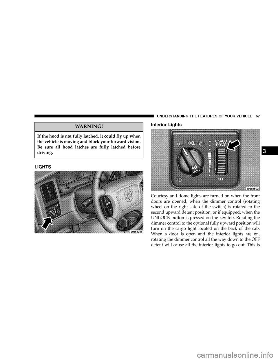
Courtesy and dome lights are turned on when the front
doors are opened, when the dimmer control (rotating
wheel on the right side of the switch) is rotated to the
second upward detent position, or if equipped, when the
UNLOCK button is pressed on the key fob. Rotating the
dimmer control to the optional fully upward position will
turn on the cargo light located on the back of the cab.
When a door is open and the interior lights are on,
rotating the dimmer control all the way down to the OFF
detent will cause all the interior lights to go out. This is
UNDERSTANDING THE FEATURES OF YOUR VEHICLE 67
3
Page 76 of 300

WARNING!
Speed Control can be dangerous where the system
can't maintain a constant speed. Your vehicle could
go too fast for the conditions, and you could lose
control. An accident could be the result. Don't use
Speed Control in heavy traffic or on roads that are
winding, icy, snow-covered, or slippery.
OVERHEAD CONSOLE
The overhead console has the following features:
²Courtesy Lights
²Garage Door Opener Ð If Equipped
²Mini-Trip Computer Ð If Equipped
Courtesy/Reading Lights
Near the front of the console are two courtesy/reading
lights.
Both lights illuminate as courtesy lights when a door is
opened, when the dimmer control is rotated to the
courtesy light position (fully upward position), or when
the UNLOCK button is pressed on the Remote Keyless
Entry transmitter, if so equipped. These lights are also
operated individually as reading lights by pressing the
recessed area of the corresponding lens.
NOTE:The courtesy/reading lights will remain on
until the switch is pressed a second time, so be sure they
have been turned off before leaving the vehicle.
76 UNDERSTANDING THE FEATURES OF YOUR VEHICLE
Page 83 of 300
WARNING!
Vehicle exhaust contains carbon monoxide, a danger-
ous gas. Do not run the vehicle's exhaust while
training the transceiver. Exhaust gas can cause seri-
ous injury or death.
WARNING!
Your motorized door or gate will open and close
while you are training the Universal Transceiver. Do
not train the transceiver if people or pets are in the
path of the door or gate. A moving door or gate can
cause serious injury or death to people and pets or
damage to objects.
2. Position the end of your hand-held transmitter 1-3
inches (3-8 cm) away from the HomeLink buttons while
keeping the indicator light in view.3. Simultaneously press and hold both the HomeLink
button that you want to train and the hand-held trans-
mitter buttons.Do not release the buttons until step 4
has been completed.
NOTE:Some gate operators and garage door openers
may require you to replace this Programming Step 3 with
procedures noted in the9Gate Operator/Canadian Pro-
gramming9section.
4. The HomeLink indicator light will flash slowly and
then rapidly after HomeLink successfully receives the
frequency signal from the hand-held transmitter. Release
both buttons after the indicator light changes from the
slow to the rapid flash.
5. Press and hold the just trained HomeLink button and
observe the indicator light. If the indicator lightstays on
constantly, programming is completeand your device
should activate when the HomeLink button is pressed
and released.
NOTE:To program the remaining two HomeLink but-
tons, begin with9Programming9step two. Do not repeat
step one.
UNDERSTANDING THE FEATURES OF YOUR VEHICLE 83
3
Page 102 of 300

Temperature gages may not show accurate readings.
When the engine is not running, turn the ignition switch
to ON to obtain accurate readings.
17. Airbag Indicator
The indicator lights and remains lit for 6 to 8
seconds when the ignition is first turned ON. If
the light does not come on when the ignition is first
turned on, or the light stays on or comes on while
driving, have the airbag system checked by an autho-
rized dealer.
18. Low Fuel Warning Light
This indicator lights when the fuel gauge reads
1/8 of a tank or less.
19. ABS Warning Light
This light monitors the Anti-Lock Brake Sys-
tem which is described elsewhere in this
manual. This light will come on when the
ignition key is turned to the ON position and
may stay on for 5 seconds. If this light remains on or
comes on during driving, it indicates that the anti-lockportion of the brake system is not functioning and that
service is required. See your authorized dealer imme-
diately.
20. Transmission Oil Temperature Warning Light
This light indicates that there is excessive
transmission fluid temperature that might
occur with severe usage such as trailer tow-
ing. If this light comes on, stop the vehicle
and run the engine at idle or faster, with the transmis-
sion in NEUTRAL until the light goes off.
21. Security
The light will flash rapidly for approximately 15 seconds
when the vehicle theft alarm is arming. The light will
flash at a slower rate after the alarm is set. The security
light will also come on for about three seconds when the
ignition is first turned ON.
22. Cargo Lamp
The Cargo Lamp light will illuminate when the Cargo
Lamp is activated from the Head Lamp switch.
102 INSTRUMENT PANEL AND CONTROLS
Page 104 of 300
U.S. federal regulations require that upon transfer of
vehicle ownership, the seller certify to the purchaser the
correct mileage that the vehicle has been driven. There-
fore, if the odometer reading is changed during repair or
replacement, be sure to keep a record of the reading
before and after the service so that the correct mileage can
be determined.
The trip odometer shows individual trip mileage. To
toggle between the odometer and the trip odometer,
press the Odometer/Trip Odometer Button.
27. Cruise Light
This indicator lights when the electronic speed control
system is turned on.
28. Coolant Temperature Light (Clusters Without A
Gauge)
This light warns of an overheated engine con-
dition. For a bulb check, this light will come on
momentarily when the ignition is turned On. If
the light turns on while driving, stop the vehicle and
shut off the engine as soon as possible.
CAUTION!
Driving with a hot engine cooling system could
damage your vehicle. If the temperature light is on,
pull over and stop the vehicle. Idle the vehicle with
the air conditioner turned off until the light turns
off. If the if the light remains on, turn the engine off
immediately, and call for service.
WARNING!
A hot engine cooling system is dangerous. You or
others could be badly burned by steam or boiling
coolant. You may want to call a service center if your
vehicle overheats. If you decide to look under the
hood yourself, see Section 7 of this manual. Follow
the warnings under the Cooling System Pressure
Cap paragraph.
104 INSTRUMENT PANEL AND CONTROLS
Page 158 of 300

case selection. When you select a different transfer case
position, the indicator lights will do the following:
If All Shift Requirements are Met
1. The current position indicator light will turn OFF.
2. The selected position indicator light will flash until the
transfer case completes the shift.
3. When the shift is complete, the indicator light for the
selected position will stop flashing and remain ON.
If One or More Shift Requirements are not Met
1. The indicator light for the current position will remain
ON.
2. The newly selected position indicator light will flash.
3. The transfer casewill notshift.
NOTE:Before retrying a selection, make certain that all
the necessary requirements for selecting a new transfer
case position have been met. To retry the selection, turn
the control knob back to the current position, wait five (5)seconds, and retry selection. To find the shift require-
ments, refer to the9Shifting Procedure9for your transfer
case, located in this section of the owner's manual.
The SERVICE 4WD warning light monitors the electric
shift 4WD system. If this light remains on after engine
start up or illuminates during driving, it means that the
4WD system is not functioning properly and that service
is required.
WARNING!
Always engage the parking brake when powering
down the vehicle if the(Service 4WD(light is
illuminated. Not engaging the parking brake may
allow the vehicle to roll which may cause personal
injury.
NOTE:Do not attempt to make a shift while only the
front or rear wheels are spinning. The NV244 transfer
case is not equipped with a synchronizer and therefore
the front and rear driveshaft speeds must be equal for the
158 STARTING AND OPERATING
Page 162 of 300

Alternate Procedure
1. Bring the vehicle to complete stop.
2. With the key ON and the engine either OFF or
RUNNING, shift the transmission into NEUTRAL (de-
press clutch on manual transmissions).
3. Rotate the transfer case control switch to the desired
position.
4. After the desired position indicator light is ON (not
flashing), shift transmission back into gear (release clutch
on manual transmissions).
NOTE:If steps 1 or 2 of either the Preferred or Alternate
Procedure are not satisfied prior to attempting the shift or
if they no longer are being met while the shift attempt is
in process, then the desired position indicator light will
flash continuously while the original position indicator
light is ON, until all requirements have been met.
NOTE:The ignition key must be ON for a shift to take
place and for the position indicator lights to be operable.
If the key is not ON then the shift will not take place and
no position indicator lights will be on or flashing.
LIMITED-SLIP DIFFERENTIAL Ð IF EQUIPPED
The limited-slip differential provides additional traction
on snow, ice, mud, sand and gravel. It improves traction
when there is a difference between the characteristics of
the surface under the right and left rear wheels. During
normal driving and cornering, the limited-slip unit is
similar to a conventional differential. But on a slippery
surface, the differential delivers more of the driving effort
to the wheel having the better traction.
WARNING!
On vehicles equipped with a limited-slip differen-
tial, never run the engine with one rear wheel off the
ground. The vehicle may drive through the rear
wheel remaining on the ground and cause you to
lose control of the vehicle.
Care should be taken to avoid sudden accelerations when
both rear wheels are on a slippery surface. This could
cause both rear wheels to spin, and allow the vehicle to
slide sideways on the crowned surface of a road or in a
turn.
162 STARTING AND OPERATING
Page 200 of 300
of the trailer lights and assure their proper functioning, a
heavy duty turn signal flasher can be installed as a
separate equipment item by your dealer.
WARNING!
The direct connection of hydraulic brake lines from
vehicle brake system to trailer system is not accept-
able. The extra load may cause brake failure and you
may be injured.
Heavy trailer towing also may require breakaway electric
trailer brakes, anti-sway devices or equalizing hitches for
safe operation. Such devices are commonly required by
state law.
For all trailer tow or heavy-duty applications it is
strongly recommended that the factory fill rear axle
lubricant be replaced with an SAE 75W-140 synthetic
gear lubricant. MopartSynthetic Gear Lubricant is of
this type.
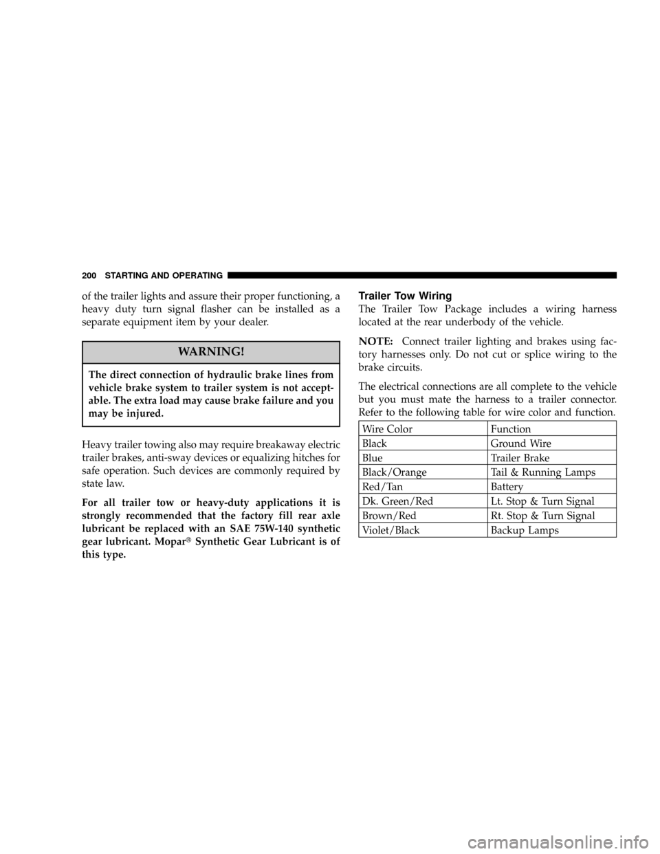
Trailer Tow Wiring
The Trailer Tow Package includes a wiring harness
located at the rear underbody of the vehicle.
NOTE:Connect trailer lighting and brakes using fac-
tory harnesses only. Do not cut or splice wiring to the
brake circuits.
The electrical connections are all complete to the vehicle
but you must mate the harness to a trailer connector.
Refer to the following table for wire color and function.
Wire Color Function
Black Ground Wire
Blue Trailer Brake
Black/Orange Tail & Running Lamps
Red/Tan Battery
Dk. Green/Red Lt. Stop & Turn Signal
Brown/Red Rt. Stop & Turn Signal
Violet/Black Backup Lamps
200 STARTING AND OPERATING