tow DODGE DAKOTA 2007 3.G Owners Manual
[x] Cancel search | Manufacturer: DODGE, Model Year: 2007, Model line: DAKOTA, Model: DODGE DAKOTA 2007 3.GPages: 400, PDF Size: 1.68 MB
Page 23 of 400

To cancel the Panic mode press and release the PANIC
button on the transmitter a second time. Panic mode will
automatically cancel after 3 minutes or if the vehicle is
started or exceeds 15 mph (24 km/h). During the Panic
Mode, the door locks and remote keyless entry systems
will function normally. Panic mode will not disarm the
security system on vehicles so equipped.
General Information
This device complies with part 15 of FCC rules and with
RS-210 of Industry Canada. Operation is subject to the
following conditions:
1. This device may not cause harmful interference.
2. This device must accept any interference that may be
received including interference that may cause undesired
operation.NOTE:Changes or modifications not expressly ap-
proved by the party responsible for compliance could
void the user’s authority to operate the equipment.
If your Remote Lock Control fails to operate from a
normal distance, check for these two conditions.
1. Weak batteries in transmitter. The expected life of
batteries is five years.
2. Closeness to a radio transmitter such as a radio station
tower, airport transmitter, military base, and some mobile
or CB radios.
Programming Additional Transmitters
Vehicles will be shipped from the assembly plants with
two transmitters programmed only for that vehicle. A
total of eight transmitters can be programmed for your
vehicle. Additional transmitters can be programmed to
your vehicle through the use of a currently programmed
fob.
THINGS TO KNOW BEFORE STARTING YOUR VEHICLE 23
2
Page 39 of 400

6. To release the belt, push the red button on the buckle.
The belt will automatically retract to its stowed position.
If necessary, slide the latch plate down the webbing to
allow the belt to retract fully.
WARNING!
A frayed or torn belt could rip apart in a collision
and leave you with no protection. Inspect the belt
system periodically, checking for cuts, frays, or loose
parts. Damaged parts must be replaced immediately.
Do not disassemble or modify the system. Seat belt
assemblies must be replaced after a collision if they
have been damaged (bent retractor, torn webbing,
etc.).
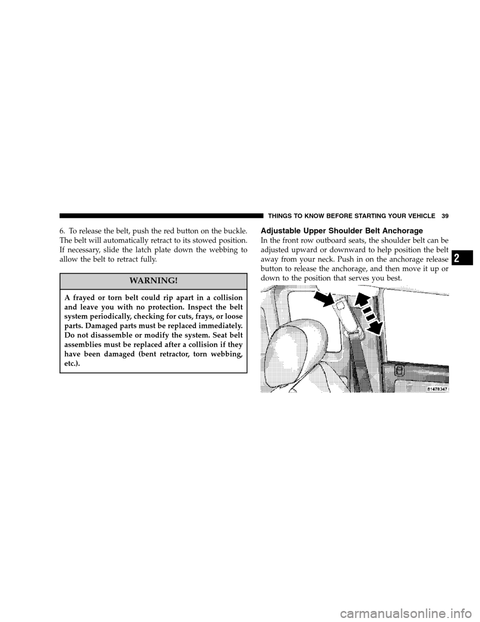
Adjustable Upper Shoulder Belt Anchorage
In the front row outboard seats, the shoulder belt can be
adjusted upward or downward to help position the belt
away from your neck. Push in on the anchorage release
button to release the anchorage, and then move it up or
down to the position that serves you best.
THINGS TO KNOW BEFORE STARTING YOUR VEHICLE 39
2
Page 64 of 400

over the top of the anchorage bars, pushing aside the seat
cover material. Then attach the tether strap to the anchor-
age located on the back of the seat, being careful to route
the tether strap to provide the most direct path between
the anchor and the child restraint. If your vehicle is
equipped with adjustable rear head restraints, raise the
head restraint and, route the tether strap under the head
restraint and between the two posts. Finally, tighten all
three straps as you push the child restraint rearward and
downward into the seat, removing slack in the straps
according to the child restraint manufacturer’s instruc-
tions.
NOTE:When using the LATCH attaching system to
install a child restraint, please ensure that all seat belts
not being used for occupant restraints are stowed and out
of reach of children. It is recommended that before
installing the child restraint, buckle the seat belt so the
seat belt is tucked behind the child restraint and out of
reach. If the buckled seat belt interferes with the childrestraint installation, instead of tucking the seat belt
behind the child restraint, route the seat belt through the
child restraint belt path and then buckle it. This should
stow the seat belt out of the reach of an inquisitive child.
Remind all children in the vehicle that the seat belts are
not toys and should not be played with, and never leave
your child unattended in the vehicle.
WARNING!
Improper installation of a child restraint to the
LATCH anchorages can lead to failure of an infant or
child restraint. The child could be badly injured or
killed. Follow the manufacturer’s directions exactly
when installing an infant or child restraint.
64 THINGS TO KNOW BEFORE STARTING YOUR VEHICLE
Page 79 of 400

MIRRORS
Inside Day/Night Mirror
The mirror should be adjusted to center on the view
through the rear window. A two-point pivot system
allows for horizontal and vertical adjustment of the
mirror.Annoying headlight glare can be reduced by moving the
small control under the mirror to the night position
(toward rear of truck). The mirror should be adjusted
while set in the day position (toward windshield).
Automatic Dimming Mirror — If Equipped
This mirror will automatically adjust for annoying head-
light glare from vehicles behind you. You can turn the
feature on or off by pressing the button at the base of the
mirror. A light in the button will indicate when the
dimming feature is activated.
UNDERSTANDING THE FEATURES OF YOUR VEHICLE 79
3
Page 81 of 400

Electric Remote-Control Mirrors
The controls for the power mirrors are located on the
driver’s door trim panel.
To adjust a mirror, turn the control wand toward the left
or right mirror positions indicated. Tilt the control wand
in the direction you want the mirror to move. When
finished adjusting the mirror, turn the control to the
center position to prevent accidentally moving a mirror.
UNDERSTANDING THE FEATURES OF YOUR VEHICLE 81
3
Page 95 of 400

The arrow on either side of the instrument cluster flashes
to indicate the direction of the turn, and proper operation
of the front and rear turn signal lights. If an indicator fails
to light when the lever is moved, it would suggest that
the switch or indicator lamp is defective.
If a defective bulb or wiring circuit is detected for the
turn signal system, the arrow indicators will flash at a
faster rate.
You can signal a lane change by moving the lever
partially up or down.
NOTE:If a turn signal has been left on for at least a mile
duration, a continuous chime will sound.Turn Signal Auto-Mode
Tap the multi-function control lever once and the turn
signal (left or right) will flash 3 times, and automatically
turn off.
Passing Light
You can signal another vehicle with your headlights by
partially pulling the multifunction lever toward the steer-
ing wheel. This will cause the high beam headlights to
turn on until the lever is released.
UNDERSTANDING THE FEATURES OF YOUR VEHICLE 95
3
Page 96 of 400

High Beam / Low Beam Select Switch
Pull the multifunction control lever fully toward the
steering wheel to switch the headlights from HIGH or
LOW beam.
WINDSHIELD WIPERS AND WASHERS
The multifunction control lever is located on the left side
of the steering column.
Windshield Wipers
The wipers and washers are operated by a switch in the
multifunction control lever. Turn the end of the handle to
select the desired wiper speed.
96 UNDERSTANDING THE FEATURES OF YOUR VEHICLE
Page 102 of 400

To Accelerate For Passing
Depress the accelerator as you would normally. When the
pedal is released, the vehicle will return to the set speed.
NOTE:When driving uphill, at elevations above 2,000
feet (610 meters), or when the vehicle is heavily loaded
(especially when towing) the vehicle may slow below the
SET speed. If the vehicle speed drops below (refer to the
table below for the speed for your specific engine), the
speed control will automatically disengage. If this hap-
pens, you can push down on the accelerator pedal to
maintain the desired speed.
Vehicles equipped with a Automatic transmission may
exhibit several downshifts under the above conditions.
To reduce the frequency of the downshifts and to im-
prove vehicle performance, it is advisable to lock out
overdrive by pressing the “TOW/HAUL” button located
at the end of the gear shifter.WARNING!
Speed Control can be dangerous where the system
can’t maintain a constant speed. Your vehicle could
go too fast for the conditions, and you could lose
control. An accident could be the result. Don’t use
Speed Control in heavy traffic or on roads that are
winding, icy, snow-covered, or slippery.
102 UNDERSTANDING THE FEATURES OF YOUR VEHICLE
Page 136 of 400

INSTRUMENT CLUSTER DESCRIPTION
1. Fuel Gauge
The fuel gauge shows level of fuel in tank when
ignition switch is in the ON position.
2. Temperature Gauge
The temperature gauge indicates engine coolant
temperature. Any reading within the normal
range indicates that the cooling system is operat-
ing satisfactorily. The gauge needle will likely indicate a
higher temperature when driving in hot weather, up
mountain grades, in heavy traffic, or when towing a
trailer. If the needle rises to the “H” mark, stop the
vehicle, shift into N (Neutral), and increase engine speed
for 2-3 minutes. If the temperature reading does not
return to normal, seek authorized service immediately.
CAUTION!
Do not leave your vehicle unattended with the
engine running as you would not be able to react to
the temperature indicator if the engine overheats.
The gauge pointer will remain near its last reading when
the engine is turned off. It will return to a true reading
when the engine is restarted.
3. Turn Signal Indicators
When a turn signal is activated, a right-pointing or
left-pointing arrow lights up and flashes to indicate the
direction of the turn. These indicators also indicate
proper operation of the front and rear turn signal lights.
If either indicator flashes at a faster rate than normal,
check for a defective bulb. If either indicator fails to light
up when the lever is moved, check for a defective fuse or
turn signal LED. A single chime is activated when the
136 INSTRUMENT PANEL AND CONTROLS
Page 141 of 400

18. Transmission Temperature Indicator
This light indicates that there is excessive trans-
mission fluid temperature that might occur
with severe usage such as trailer towing. If this
light comes on, stop the vehicle and run the
engine at idle or faster, with the transmission in NEU-
TRAL until the light goes off.
19. Electronic Throttle Control (ETC) – If Equipped
This light informs you of a problem with the
Electronic Throttle Control system. If a prob-
lem is detected the light will come on while the
engine is running. If the light remains lit with
the engine running your vehicle will usually be drivable,
however, see your dealer for service as soon as possible.
If the light is flashing when the engine is running,
immediate service is required and you may experience
reduced performance, an elevated/rough idle or engine
stall and your vehicle may require towing. The light will
come on when the ignition is first turned on and remainon for 15 seconds as a bulb check. If the light does not
come on during starting, have the system checked by an
authorized dealer.
20. BRAKE System Warning Light
This light will light when the ignition key is turned to the
ON position and will remain on for a few seconds. If the
light stays on, it may be an indication that the parking
brake has not been released, or there is a low brake fluid
level. If the light remains on when the parking brake has
been disengaged, and the fluid level is at the full mark on
the master cylinder reservoir, it indicates a possible brake
hydraulic system malfunction. In this case, the light will
remain on until the condition has been corrected. If the
parking brake is applied, the light will flash when the
gear position is out of park for automatic transmissions.
If brake failure is indicated, immediate repair is neces-
sary. Operating the vehicle in this condition is danger-
ous!
INSTRUMENT PANEL AND CONTROLS 141
4