sensor DODGE DAKOTA 2009 3.G Owners Manual
[x] Cancel search | Manufacturer: DODGE, Model Year: 2009, Model line: DAKOTA, Model: DODGE DAKOTA 2009 3.GPages: 449, PDF Size: 10.96 MB
Page 52 of 449
WARNING! (Continued)
²If the vehicle has window bags, they also need
room to inflate. Do not lean against the door or
window. Sit upright in the center of the seat.
Airbag System Components
The airbag system consists of the following:
²Occupant Restraint Controller
²Side Remote Acceleration Sensors ± if equipped
²Airbag Warning Light
²Driver Airbag
²Passenger Airbag
²Window Bags above side windows ± if equipped
²Steering Wheel and Column
²Instrument Panel
²Interconnecting Wiring
²Knee Impact Bolsters
²Front Acceleration Sensors
²Driver and Front Passenger Seat Belt Pretensioners
How the Airbag System Works
²
TheOccupant Restraint Controller (ORC)determines
if a frontal collision is severe enough to require the
airbags to inflate. The front airbag inflators are de-
signed to provide different rates of airbag inflation
from direction provided by the ORC. The ORC will not
detect rollover.
The ORC also monitors the readiness of the electronic
parts of the system whenever the ignition switch is in
the START or RUN position. These include all of the
items listed above, except the steering wheel and
column, and knee bolsters. If the key is in the OFF
50 THINGS TO KNOW BEFORE STARTING YOUR VEHICLE
Page 55 of 449
If a Deployment Occurs
The airbag system is designed to deploy the airbags
when the impact sensors detect a moderate-to-severe
frontal collision, to help restrain the driver and front
passenger, and then immediately deflate.
NOTE:A frontal collision that is not severe enough to
need airbag protection will not activate the system. This
does not mean something is wrong with the airbag
system.
If you do have a collision that deploys the airbags, any or
all of the following may occur:
²The nylon airbag material may sometimes cause abra-
sions and/or skin reddening to the driver and front
passenger as the airbags deploy and unfold. The
abrasions are similar to friction rope burns or those
you might get sliding along a carpet or gymnasium
floor. They are not caused by contact with chemicals.
They are not permanent and normally heal quickly.However, if you haven't healed significantly within a
few days, or if you have any blistering, see your doctor
immediately. As the airbags deflate, you may see some
smoke-like particles. The particles are a normal by-
product of the process that generates the nontoxic gas
used for airbag inflation. These airborne particles may
irritate the skin, eyes, nose, or throat. If you have skin
or eye irritation, rinse the area with cool water. For
nose or throat irritation, move to fresh air. If the
irritation continues, see your doctor. If these particles
settle on your clothing, follow the garment manufac-
turer's instructions for cleaning.²It is not advisable to drive your vehicle after the
airbags have deployed. If you are involved in another
collision, the airbags will not be in place to protect you.
THINGS TO KNOW BEFORE STARTING YOUR VEHICLE 53
2
Page 58 of 449
check the fuse block for blown fuses. Refer to the label
located on the inside of the fuse block cover for the
proper airbag fuses. See your authorized dealer if the
fuse is good.
Event Data Recorder (EDR)
In the event of an accident, your vehicle is designed to
record up to five seconds of specific vehicle data param-
eters (see the following list) in an event data recorder,
prior to the moment of airbag deployment, or near
deployment, and up to a quarter-second of high-speed
deceleration data during, and/or after, airbag deploy-
ment. EDR data are ONLY recorded if an airbag deploys,
or nearly deploys, and are otherwise unavailable.
NOTE:
1. A near-deployment event occurs when the airbag
sensor detects severe vehicle deceleration usually indica-
tive of a crash, but not severe enough to warrant airbag
deployment.2. Under certain circumstances, EDR data may not be
recorded (e.g., loss of battery power).
In conjunction with other data gathered during a com-
plete accident investigation, the electronic data may be
used by Chrylser LLC, and others, to learn more about
the possible causes of crashes and associated injuries, in
order to assess and improve vehicle performance. In
addition to crash investigations initiated by Chrylser
LLC, such investigations may be requested by customers,
insurance carriers, government officials, and professional
crash researchers, such as those associated with univer-
sities, and with hospital and insurance organizations.
In the event that an investigation is undertaken by
Chrylser LLC (regardless of initiative), the company, or
its designated representative, will first obtain permission
of the appropriate custodial entity for the vehicle (usually
the vehicle owner or lessee) before accessing the elec-
tronic data stored, unless ordered to download data by a
56 THINGS TO KNOW BEFORE STARTING YOUR VEHICLE
Page 143 of 449
NOTE:Magnetic materials should be kept away from
the Overhead Console. This is where the compass sensor
is located.
Manual Compass Calibration
NOTE:To ensure proper compass calibration, make
sure the compass variance is properly set before manu-
ally calibrating the compass.
If the compass appears erratic and the CAL symbol does
not appear, you must manually put the compass into the
ªCalibrationº mode.
To Put Into a Calibration Mode
Turn the ignition ON and set the display to ªCompass/
Temperature.º Press and hold the RESET button to
change the display between VAR (compass variance) and
CAL (compass calibration) modes. When the CAL sym-
bol is displayed, complete one 360 degree turn in an areafree from large metal objects or power lines. The CAL
symbol will turn off and the compass will function
normally.
Compass Varianceis the difference between magnetic
North and geographic North. In some areas of the
country, the difference between magnetic and geographic
North is great enough to cause the compass to give false
readings. If this occurs, the compass variance must be set
according to the Compass Variance Map.
UNDERSTANDING THE FEATURES OF YOUR VEHICLE 141
3
Page 144 of 449
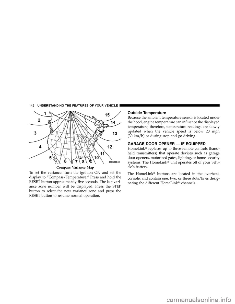
To set the variance: Turn the ignition ON and set the
display to ªCompass/Temperature.º Press and hold the
RESET button approximately five seconds. The last vari-
ance zone number will be displayed. Press the STEP
button to select the new variance zone and press the
RESET button to resume normal operation.
Outside Temperature
Because the ambient temperature sensor is located under
the hood, engine temperature can influence the displayed
temperature; therefore, temperature readings are slowly
updated when the vehicle speed is below 20 mph
(30 km/h) or during stop-and-go driving.
GARAGE DOOR OPENER Ð IF EQUIPPED
HomeLinktreplaces up to three remote controls (hand-
held transmitters) that operate devices such as garage
door openers, motorized gates, lighting, or home security
systems. The HomeLinktunit operates off of your vehi-
cle's battery.
The HomeLinktbuttons are located in the overhead
console, and contain one, two, or three dots/lines desig-
nating the different HomeLinktchannels.
Compass Variance Map
142 UNDERSTANDING THE FEATURES OF YOUR VEHICLE
Page 180 of 449
CAUTION!
The TPMS has been optimized for the original
equipment tires and wheels. TPMS pressures and
warning have been established for the tire size
equipped on your vehicle. Undesirable system opera-
tion or sensor damage may result when using re-
placement equipment that is not of the same size,
type, and/or style. Aftermarket wheels can cause
sensor damage. Do not use tire sealant from a can, or
balance beads if your vehicle is equipped with a
TPMS, as damage to the sensors may result.
23. Airbag Warning Light
The airbag warning light will illuminate and
remain lit for six to eight seconds when the
ignition is first turned ON. If the light does not
illuminate when the ignition is first turned ON,or the light stays on or comes on while driving, have the
airbag system checked by an authorized dealer.
24. 4WD Indicator
The 4WD indicator illuminates when the transfer case is
in 4WD position.
25. SVC (Service) 4WD Indicator
The SVC 4WD illuminates when the ignition key is
turned to the ON position and will stay on for two
seconds. If the light stays on or illuminates during
driving, it means that the 4WD system is not functioning
properly and that service is required.
26. Cruise Indicator
The cruise indicator illuminates when the electronic
speed control system is turned on.
178 UNDERSTANDING YOUR INSTRUMENT PANEL
Page 296 of 449
CAUTION!
²The TPMS has been optimized for the original
equipment tires and wheels. TPMS pressures have
been established for the tire size equipped on your
vehicle. Undesirable system operation or sensor
damage may result when using replacement
equipment that is not of the same size, type, and/or
style. Aftermarket wheels can cause sensor dam-
age. Do not use aftermarket tire sealants or balance
beads if your vehicle is equipped with a TPMS, as
damage to the sensors may result.
²After inspecting or adjusting the tire pressure
always reinstall the valve stem cap. This will
prevent moisture and dirt from entering the valve
stem, which could damage the tire pressure moni-
toring sensor.NOTE:
²The TPMS is not intended to replace normal tire care
and maintenance, or to provide warning of a tire
failure or condition.
²The TPMS should not be used as a tire pressure gauge
while adjusting your tire pressure.
²Driving on a significantly under-inflated tire causes
the tire to overheat and can lead to tire failure.
Under-inflation also reduces fuel efficiency and tire
tread life, and may affect the vehicle's handling and
stopping ability.
²The TPMS is not a substitute for proper tire mainte-
nance, and it is the driver 's responsibility to maintain
correct tire pressure using an accurate tire gauge, even
if under-inflation has not reached the level to trigger
illumination of the Tire Pressure Monitoring Telltale
Lamp.
294 STARTING AND OPERATING
Page 297 of 449
²Seasonal temperature changes will affect tire pressure,
and the TPMS will monitor the actual tire pressure in
the tire.
Base System ± If Equipped
The Tire Pressure Monitor System (TPMS) uses wireless
technology with wheel rim mounted electronic sensors to
monitor tire pressure levels. Sensors, mounted to each
wheel as part of the valve stem, transmit tire pressure
readings to the receiver module.
NOTE:It is particularly important for you to check the
tire pressure in all of your tires regularly and to maintain
the proper pressure.
The TPMS consists of the following components:
²Receiver module
²Four tire pressure monitoring sensors
²Tire Pressure Monitoring Telltale LampThe Tire Pressure Monitoring Telltale Lamp will
illuminate in the instrument cluster, and an au-
dible chime will be activated when one or more of
the four active road tire pressures are low. Should this
occur, you should stop as soon as possible, check the
inflation pressure of each tire on your vehicle, and inflate
each tire to the vehicle's recommended cold placard
pressure value. The system will automatically update
and the Tire Pressure Monitoring Telltale Lamp will
extinguish once the updated tire pressures have been
received. The vehicle may need to be driven for up to
10 minutes above 15 mph (25 km/h) to receive this
information.
The Tire Pressure Monitoring Telltale Lamp will flash on
and off for 75 seconds, and remain on solid when a
system fault is detected. The system fault will also sound
a chime. If the ignition key is cycled, this sequence will
repeat, providing the system fault still exists. The Tire
Pressure Monitoring Telltale Lamp will turn off when the
STARTING AND OPERATING 295
5
Page 298 of 449
fault condition no longer exists. A system fault can occur
by any of the following scenarios: 1) Jamming due to
electronic devices or driving next to facilities emitting the
same radio frequencies as the TPM sensors; 2) Installing
some form of aftermarket window tinting that affects
radio wave signals; 3) Lots of snow or ice around the
wheels or wheel housings; 4) Using tire chains on the
vehicle; 5) Using wheels/tires not equipped with TPM
sensors.
NOTE: Your vehicle is equipped with a non-matching
full size spare wheel and tire assembly.
1. This spare tire does not have a tire pressure monitor-
ing sensor. Therefore, the TPMS will not monitor the tire
pressure in the spare tire.
2. If you install the full size spare tire in place of a road
tire that has a pressure below the low-pressure warninglimit, upon the next ignition key cycle a chime will sound
and the TPM Telltale Lamp will still turn ON due to the
low tire.
3. However, after driving the vehicle for up to 10 min-
utes above 15 mph (25 km/h), the TPM Telltale Lamp
will flash on and off for 75 seconds and then remain on
solid.
4. For each subsequent ignition key cycle, a chime will
sound and the TPM Telltale Light will flash on and off for
75 seconds and then remain on solid.
5. Once you repair or replace the original road tire, and
reinstall it on the vehicle in place of the full size spare tire,
the TPMS will update automatically and the TPM Telltale
Lamp will turn OFF, as long as no tire pressure is below
the low-pressure warning limit in any of the four active
road tires. The vehicle may need to be driven for up to
10 minutes above 15 mph (25 km/h) in order for the
TPMS to receive this information.
296 STARTING AND OPERATING
Page 299 of 449
General Information
This device complies with part 15 of the FCC rules and
RSS 210 of Industry Canada. Operation is subject to the
following conditions:
²This device may not cause harmful interference.
²This device must accept any interference received,
including interference that may cause undesired
operation.
The tire pressure sensors are covered under one of the
following licenses:
United States.....................KR5S120123
Canada........................2671-S120123
FUEL REQUIREMENTS
All engines (except 4.7L HO engines) are
designed to meet all emissions regulations,
and provide excellent fuel economy and
performance when using high-quality un-
leaded ªregularº gasoline having an oc-
tane rating of 87. The use of premium
gasoline is not recommended. Under normal conditions,
the use of premium gasoline will not provide a benefit
over high-quality regular gasolines, and in some circum-
stances may result in poorer performance.
The 4.7L HO engine is designed to meet all
emissions regulations, and provide satis-
factory fuel economy and performance
when using high-quality unleaded gaso-
line having an octane range of 87 to 91. The
manufacturer recommends the use of
91 octane for optimum performance.
STARTING AND OPERATING 297
5