ECU DODGE DAKOTA 2011 3.G User Guide
[x] Cancel search | Manufacturer: DODGE, Model Year: 2011, Model line: DAKOTA, Model: DODGE DAKOTA 2011 3.GPages: 76, PDF Size: 4.62 MB
Page 9 of 76
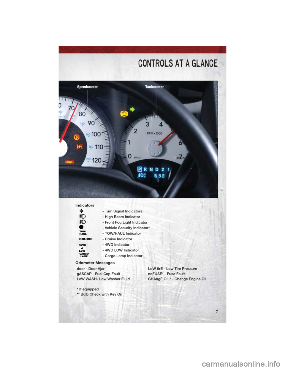
Indicators
- Turn Signal Indicators
- High Beam Indicator
- Front Fog Light Indicator
- Vehicle Security Indicator*
- TOW/HAUL Indicator
- Cruise Indicator
- 4WD Indicator
- 4WD LOW Indicator
- Cargo Lamp Indicator
Odometer Messages
door - Door AjarLoW tirE - Low Tire Pressure
gASCAP - Fuel Cap Fault noFUSE* - Fuse Fault
LoW WASH- Low Washer Fluid CHAngE OIL* - Change Engine Oil
* If equipped
** Bulb Check with Key On
CONTROLS AT A GLANCE
7
Page 10 of 76
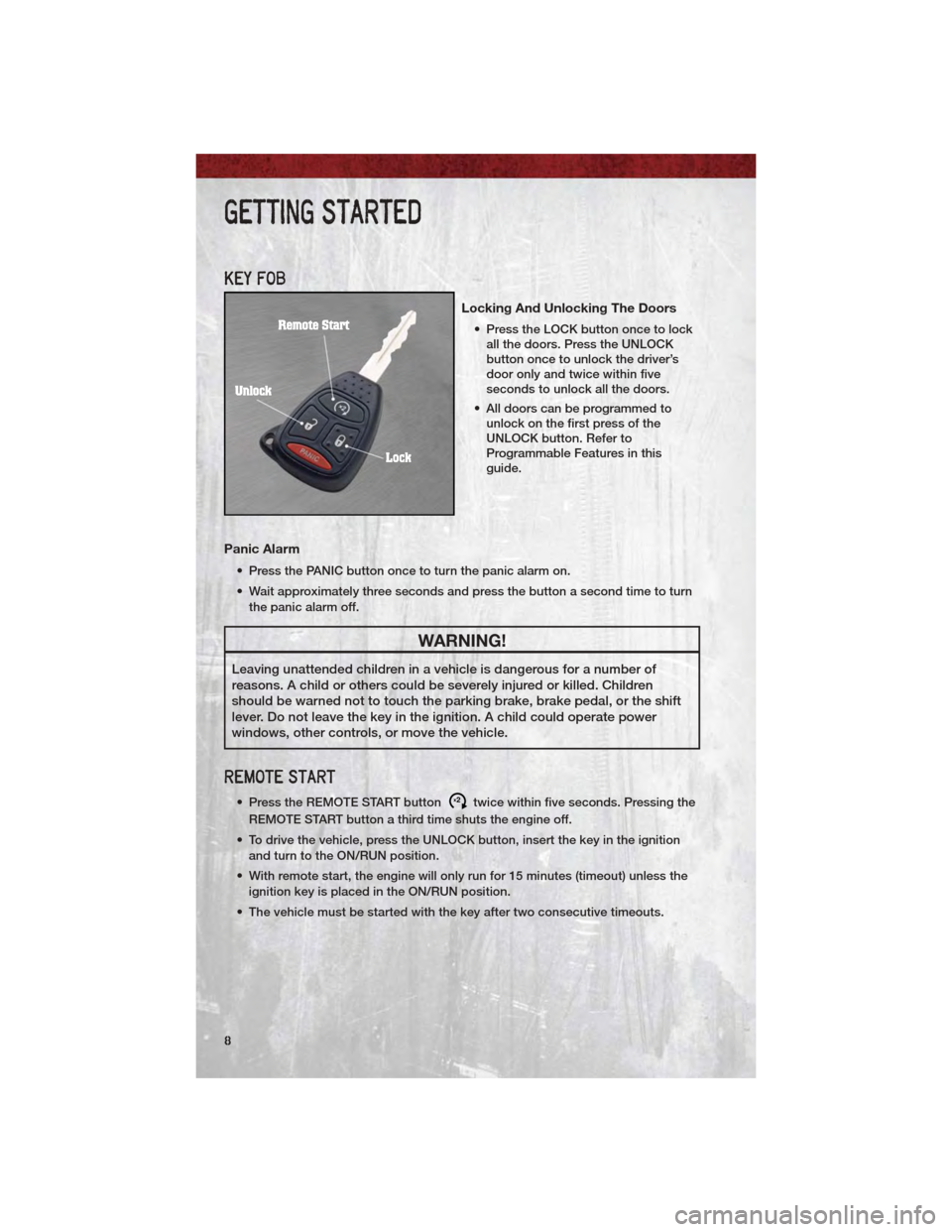
KEY FOB
Locking And Unlocking The Doors
• Press the LOCK button once to lockall the doors. Press the UNLOCK
button once to unlock the driver’s
door only and twice within five
seconds to unlock all the doors.
• All doors can be programmed to unlock on the first press of the
UNLOCK button. Refer to
Programmable Features in this
guide.
Panic Alarm
• Press the PANIC button once to turn the panic alarm on.
• Wait approximately three seconds and press the button a second time to turn
the panic alarm off.
WARNING!
Leaving unattended children in a vehicle is dangerous for a number of
reasons. A child or others could be severely injured or killed. Children
should be warned not to touch the parking brake, brake pedal, or the shift
lever. Do not leave the key in the ignition. A child could operate power
windows, other controls, or move the vehicle.
REMOTE START
• Press the REMOTE START buttonx2twice within five seconds. Pressing the
REMOTE START button a third time shuts the engine off.
• To drive the vehicle, press the UNLOCK button, insert the key in the ignition and turn to the ON/RUN position.
• With remote start, the engine will only run for 15 minutes (timeout) unless the ignition key is placed in the ON/RUN position.
• The vehicle must be started with the key after two consecutive timeouts.
GETTING STARTED
8
Page 13 of 76
CHILD RESTRAINTS
• Children 12 years and under should ride properly buckled up in a rear seat, ifavailable. According to crash statistics, children are safer when properly
restrained in the rear seats rather than in the front.
• Every state in the United States and all Canadian provinces require that small children ride in proper restraint systems. This is the law, and you can be
prosecuted for ignoring it.
Installing The LATCH - Compatible Child Restraint System
• Your vehicle is equipped with the child restraint anchorage system calledLATCH, which stands for Lower Anchors and Tether for CHildren.
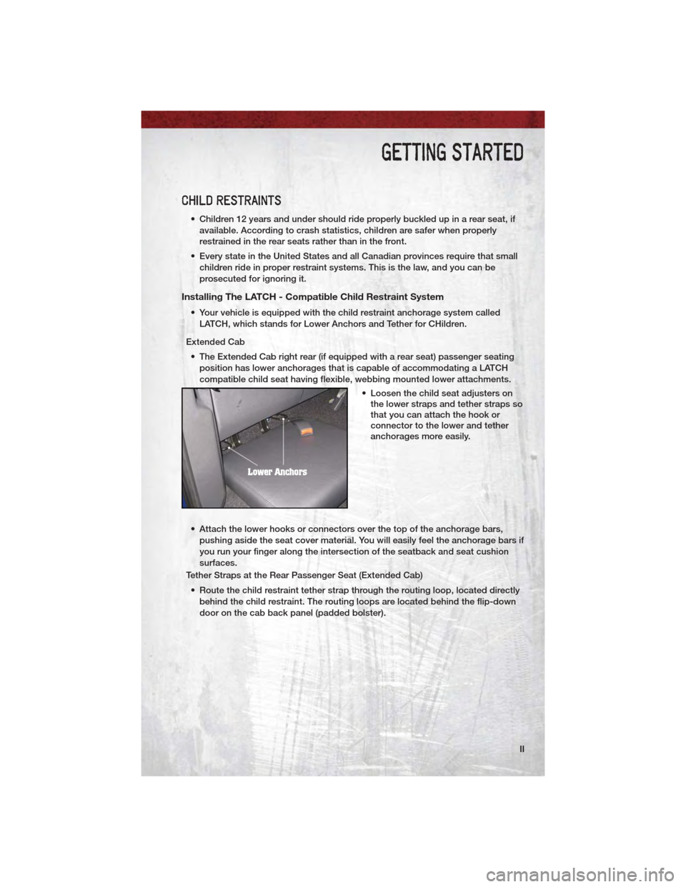
Extended Cab • The Extended Cab right rear (if equipped with a rear seat) passenger seating position has lower anchorages that is capable of accommodating a LATCH
compatible child seat having flexible, webbing mounted lower attachments.
• Loosen the child seat adjusters onthe lower straps and tether straps so
that you can attach the hook or
connector to the lower and tether
anchorages more easily.
• Attach the lower hooks or connectors over the top of the anchorage bars, pushing aside the seat cover material. You will easily feel the anchorage bars if
you run your finger along the intersection of the seatback and seat cushion
surfaces.
Tether Straps at the Rear Passenger Seat (Extended Cab)
• Route the child restraint tether strap through the routing loop, located directly behind the child restraint. The routing loops are located behind the flip-down
door on the cab back panel (padded bolster).
GETTING STARTED
11
Page 15 of 76
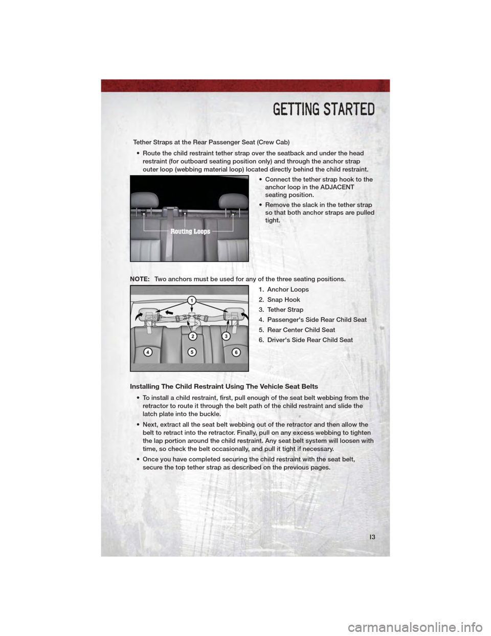
Tether Straps at the Rear Passenger Seat (Crew Cab)• Route the child restraint tether strap over the seatback and under the head restraint (for outboard seating position only) and through the anchor strap
outer loop (webbing material loop) located directly behind the child restraint.
• Connect the tether strap hook to theanchor loop in the ADJACENT
seating position.
• Remove the slack in the tether strap so that both anchor straps are pulled
tight.
NOTE: Two anchors must be used for any of the three seating positions.
1. Anchor Loops
2. Snap Hook
3. Tether Strap
4. Passenger's Side Rear Child Seat
5. Rear Center Child Seat
6. Driver's Side Rear Child Seat
Installing The Child Restraint Using The Vehicle Seat Belts
• To install a child restraint, first, pull enough of the seat belt webbing from theretractor to route it through the belt path of the child restraint and slide the
latch plate into the buckle.
• Next, extract all the seat belt webbing out of the retractor and then allow the belt to retract into the retractor. Finally, pull on any excess webbing to tighten
the lap portion around the child restraint. Any seat belt system will loosen with
time, so check the belt occasionally, and pull it tight if necessary.
• Once you have completed securing the child restraint with the seat belt, secure the top tether strap as described on the previous pages.
GETTING STARTED
13
Page 16 of 76
WARNING!
• In a collision, an unrestrained child, even a tiny baby, can become aprojectile inside the vehicle. The force required to hold even an infant on
your lap could become so great that you could not hold the child, no
matter how strong you are. The child and others could be severely
injured or killed. Any child riding in your vehicle should be in a proper
restraint for the child's size.
• Improper installation of a child restraint to the LATCH anchorages can lead to failure of an infant or child restraint. The child could be severely
injured or killed. Follow the manufacturer’s directions exactly when
installing an infant or child restraint.
• An incorrectly anchored tether strap could lead to increased head motion and possible injury to the child. Use only the anchor positions directly
behind the child seat to secure a child restraint top tether strap.
• Rearward-facing child seats must never be used in the front seat of a vehicle with a front passenger airbag. An airbag deployment could cause
severe injury or death to infants in this position.
FRONT SEATS
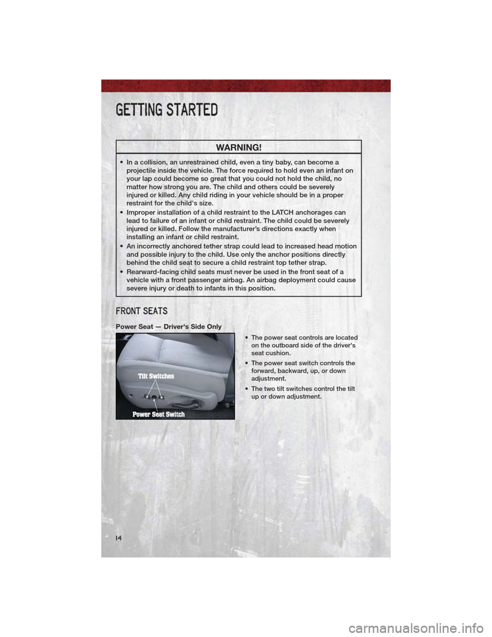
Power Seat — Driver's Side Only
• The power seat controls are locatedon the outboard side of the driver's
seat cushion.
• The power seat switch controls the forward, backward, up, or down
adjustment.
• The two tilt switches control the tilt up or down adjustment.
GETTING STARTED
14
Page 30 of 76
• For vehicles equipped with Video Entertainment System (VES)™, refer to theUconnect™ Voice Command section of the Uconnect™ User's Manual on the
DVD for further details.
• For vehicles not equipped with VES™, refer to your vehicle Owner's Manual on the DVD for Uconnect™ Voice Command information.
NOTE: To access the tutorial, press the Voice Command button
.Afterthe
BEEP, say “tutorial”. Press any hard-key/button or touch the display (Touch-Screen
radio) to cancel the tutorial.
WARNING!
Any voice commanded system should be used only in safe driving
conditions following local laws and phone use. All attention should be kept
on the roadway ahead. Failure to do so may result in a collision causing you
and others to be severely injured or killed.
PROGRAMMABLE FEATURES
• The following features may be programmed using the Key Fob transmitter or the ignition switch and driver's door lock switch.
NOTE: Pressing the LOCK button while you are inside the vehicle will activate the
Vehicle Security Alarm. Opening a door with the Vehicle Security Alarm activated
will cause the alarm to sound. Press the UNLOCK button to deactivate the Vehicle
Security Alarm.
Unlock On First Press
• To unlock either the driver's side, or all doors, on the first press of the UNLOCK button:
• Press and hold the LOCK button for at least 4 seconds, but no longer than
10 seconds. Then, press and hold the UNLOCK button while still holding the
LOCK button.
• Release both buttons at the same time.
Auto Unlock Doors On Exit
• To have all of the vehicle doors unlock when any door is opened: • Enter your vehicle and close all the doors.
• Fasten your seatbelt.
• Within 15 seconds, cycle the ignition switch between LOCK and ON andthen back to LOCK four times, ending up in the LOCK position (do not start
the engine).
• Press the power door UNLOCK switch to unlock the doors. A single chime will indicate that programming is complete.
ELECTRONICS
28
Page 35 of 76
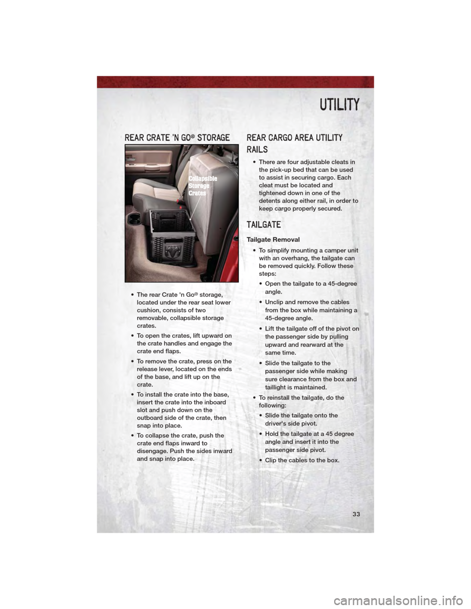
REAR CRATE 'N GO®STORAGE
• The rear Crate 'n Go®storage,
located under the rear seat lower
cushion, consists of two
removable, collapsible storage
crates.
• To open the crates, lift upward on the crate handles and engage the
crate end flaps.
• To remove the crate, press on the release lever, located on the ends
of the base, and lift up on the
crate.
• To install the crate into the base, insert the crate into the inboard
slot and push down on the
outboard side of the crate, then
snap into place.
• To collapse the crate, push the crate end flaps inward to
disengage. Push the sides inward
and snap into place.
REAR CARGO AREA UTILITY
RAILS
• There are four adjustable cleats inthe pick-up bed that can be used
to assist in securing cargo. Each
cleat must be located and
tightened down in one of the
detents along either rail, in order to
keep cargo properly secured.
TAILGATE
Tailgate Removal
• To simplify mounting a camper unitwith an overhang, the tailgate can
be removed quickly. Follow these
steps:
• Open the tailgate to a 45-degree
angle.
• Unclip and remove the cables from the box while maintaining a
45-degree angle.
• Lift the tailgate off of the pivot on the passenger side by pulling
upward and rearward at the
same time.
• Slide the tailgate to the passenger side while making
sure clearance from the box and
taillight is maintained.
• To reinstall the tailgate, do the following:
• Slide the tailgate onto the
driver's side pivot.
• Hold the tailgate at a 45 degree angle and insert it into the
passenger side pivot.
• Clip the cables to the box.
UTILITY
33
Page 36 of 76
Two–Position Tailgate/Upper Load
Platform
• Your tailgate can be opened to thefull-open or the partial-open
position. The partial-open position
is for loading objects longer than
the length of the bed (sheets of
plywood, etc.) by creating an upper
load platform.
Installing Lumber • Place lumber across the box in the indentations provided above the
wheel housings and in the
bulkhead dividers, to form the floor.
There are indents in the sheet
metal (or bed liner if equipped) on
the inner side of the box in front
(Crew Cab
®only) and behind both
wheel housings.
• Secure the tailgate in the partially-open position.
• Open the tailgate slightly.
• Snap the tailgate support cable between the cable guide and the
tailgate bumper. Do this on both
sides of the tailgate.
• To return the tailgate to the full-open position:
• Lift up on tailgate.
• Remove both cables from
between the cable guides and
the tailgate bumpers, and lower
the tailgate.
CAUTION!
• Care should always beexercised when operating a
vehicle with cargo. Vehicle
speeds may need to be
reduced. Severe turns or rough
roads may cause shifting or
bouncing of the cargo that may
result in vehicle damage.
(Continued)
CAUTION!(Continued)
• Ensure the load is securely tieddown and is properly identified
according to local laws if it
extends beyond the tail lights.
• Loading should not exceed 400 lbs (181 kg) of material
suspended above the
wheelhouse and partially open
tailgate or vehicle damage may
result.
TRAILER TOWING WEIGHTS
(MAXIMUM TRAILER WEIGHT
RATINGS)
NOTE: For trailer towing information
(maximum trailer weight ratings) refer to
the following website addresses:
• http:// www.ramtrucks.com/towing
• http:// www.ramtruck.ca (Canada)
RECREATIONAL TOWING
(BEHIND MOTORHOME, ETC.)
Two-Wheel Drive Models
• Recreational towing of two-wheel
drive models is not allowable.
Towing the vehicle with the
transmission in NEUTRAL can
cause severe transmission
damage. Removal of the driveshaft
for towing is not recommended,
since this would allow fluid to drain
from the transmission.
UTILITY
34
Page 44 of 76
JACKING AND TIRE CHANGING
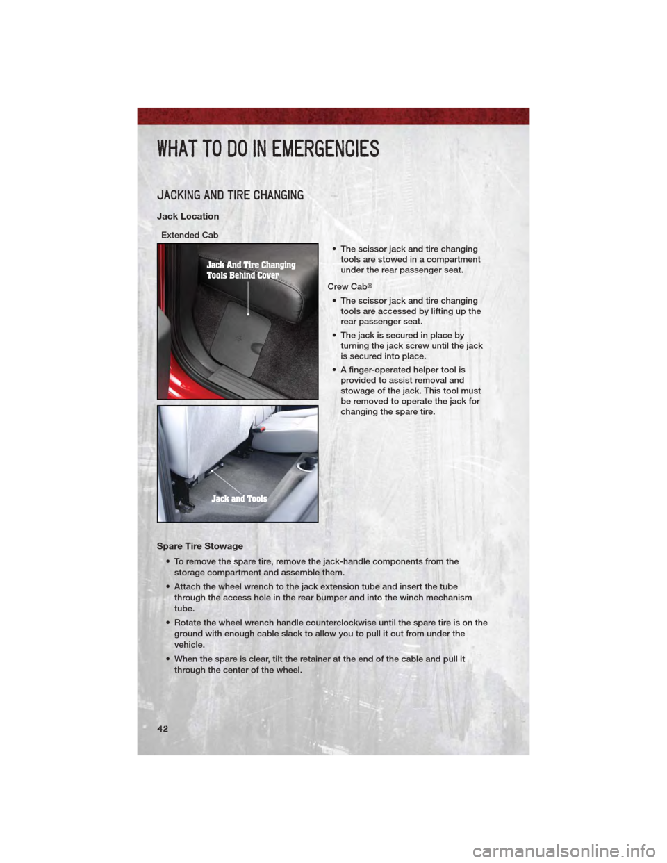
Jack Location
Extended Cab• The scissor jack and tire changingtools are stowed in a compartment
under the rear passenger seat.
Crew Cab
®
• The scissor jack and tire changing tools are accessed by lifting up the
rear passenger seat.
• The jack is secured in place by turning the jack screw until the jack
is secured into place.
• A finger-operated helper tool is provided to assist removal and
stowage of the jack. This tool must
be removed to operate the jack for
changing the spare tire.
Spare Tire Stowage
• To remove the spare tire, remove the jack-handle components from the
storage compartment and assemble them.
• Attach the wheel wrench to the jack extension tube and insert the tube through the access hole in the rear bumper and into the winch mechanism
tube.
• Rotate the wheel wrench handle counterclockwise until the spare tire is on the ground with enough cable slack to allow you to pull it out from under the
vehicle.
• When the spare is clear, tilt the retainer at the end of the cable and pull it through the center of the wheel.
WHAT TO DO IN EMERGENCIES
42
Page 48 of 76
• Raise the vehicle by turning the jack screw clockwise. Raise the vehicle onlyuntil the tire just clears the surface and enough clearance is obtained to install
the spare tire.
• Remove the lug nuts and wheel.
• Position the spare wheel/tire on the vehicle and install the lug nuts with the cone-shaped end toward the wheel. Lightly tighten the lug nuts clockwise. To
avoid the risk of forcing the vehicle off the jack, do not tighten the nuts fully
until the vehicle has been lowered.
• Lower the vehicle by turning the jack screw counterclockwise, and remove the jack and wheel blocks.
• Finish tightening the lug nuts. Push down on the wrench while tightening for increased leverage. Alternate nuts until each one has been tightened twice.
The correct wheel nut tightness is 120 to 160 ft lbs (163 to 217 N·m). If in doubt
about the correct tightness, have them checked with a torque wrench by your
authorized dealer or at a service station.
• Secure the jack and tools in their proper locations.
• For convenience in checking the spare tire inflation, stow with the valve stem toward the rear of the vehicle. Continue winching up the tire until you hear the
winch click three times.
NOTE: To Stow the Flat or Spare: The wheel retainer does not fit through the
center of the aluminum wheel. The tire must be stored in a safe manner in the bed
of the truck.
WARNING!
• Do not attempt to change a tire on the side of the vehicle close to moving traffic. Pull far enough off the road to avoid the danger of being hit when
operating the jack or changing the wheel.
• Getting under a jacked-up vehicle is dangerous. The vehicle could slip off the jack and fall on you. You could be crushed. Never get any part of your
body under a vehicle that is on a jack. If you need to get under a raised
vehicle, take it to a service center where it can be raised on a lift.
• The jack is designed to use as a tool for changing tires only. The jack should not be used to lift the vehicle for service purposes. The vehicle
should be jacked on a firm, level surface only. Avoid ice or slippery areas.
• If it is necessary to retrieve the spare tire from under the vehicle on the side of the vehicle close to moving traffic, pull far enough off the road to
avoid the danger of being hit.
• Do not attempt to change a tire on the side of the vehicle close to moving traffic. Pull far enough off the road to avoid being hit when operating the
jack or changing the wheel.
• Carefully follow these tire changing procedures to help prevent personal injury or damage to your vehicle: Always park on a firm, level surface as
far from the edge of the roadway as possible before raising the vehicle.
(Continued)
WHAT TO DO IN EMERGENCIES
46