Esc DODGE DART 2013 PF / 1.G Service Manual
[x] Cancel search | Manufacturer: DODGE, Model Year: 2013, Model line: DART, Model: DODGE DART 2013 PF / 1.GPages: 604, PDF Size: 4.72 MB
Page 470 of 604
Gross Axle Weight Rating (GAWR)
The GAWR is the maximum capacity of the front and rear
axles. Distribute the load over the front and rear axles
evenly. Make sure that you do not exceed either the front
or rear GAWR. Refer to “Vehicle Loading/Vehicle Certi-
fication Label” in “Starting and Operating” for further
information.
WARNING!
It is important that you do not exceed the maximum
front or rear GAWR. A dangerous driving condition
can result if either rating is exceeded. You could lose
control of the vehicle and have a collision.
Tongue Weight (TW)
The tongue weight is the downward force exerted on the
hitch ball by the trailer. In most cases it should not be less
than 10% or more than 15% of the trailer load. You must
consider this as part of the load on your vehicle.
Frontal Area
The frontal area is the maximum height multiplied by the
maximum width of the front of a trailer.
Trailer Sway Control
The trailer sway control is a telescoping link that can be
installed between the hitch receiver and the trailer tongue
that typically provides adjustable friction associated with
the telescoping motion to dampen any unwanted trailer
swaying motions while traveling.
Weight-Carrying Hitch
A weight-carrying hitch supports the trailer tongue
weight, just as if it were luggage located at a hitch ball or
some other connecting point of the truck. These kind of
hitches are the most popular on the market today and
they are commonly used to tow small- and medium-
sized trailers.
468 STARTING AND OPERATING
Page 515 of 604
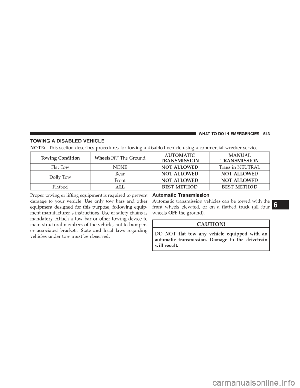
TOWING A DISABLED VEHICLE
NOTE:This section describes procedures for towing a disabled vehicle using a commercial wrecker service.
Towing Condition WheelsOFF The GroundAUTOMATIC
TRANSMISSION MANUAL
TRANSMISSION
Flat Tow NONE NOT ALLOWEDTrans in NEUTRAL
Dolly Tow Rear
NOT ALLOWED NOT ALLOWED
Front NOT ALLOWED NOT ALLOWED
Flatbed ALLBEST METHOD BEST METHOD
Proper towing or lifting equipment is required to prevent
damage to your vehicle. Use only tow bars and other
equipment designed for this purpose, following equip-
ment manufacturer ’s instructions. Use of safety chains is
mandatory. Attach a tow bar or other towing device to
main structural members of the vehicle, not to bumpers
or associated brackets. State and local laws regarding
vehicles under tow must be observed.
Automatic Transmission
Automatic transmission vehicles can be towed with the
front wheels elevated, or on a flatbed truck (all four
wheels OFFthe ground).
CAUTION!
DO NOT flat tow any vehicle equipped with an
automatic transmission. Damage to the drivetrain
will result.
6
WHAT TO DO IN EMERGENCIES 513
Page 544 of 604
Brake System
In order to assure brake system performance, all brake
system components should be inspected periodically.
Refer to the “Maintenance Schedule” for the proper
maintenance intervals.
WARNING!
Riding the brakes can lead to brake failure and
possibly a collision. Driving with your foot resting or
riding on the brake pedal can result in abnormally
high brake temperatures, excessive lining wear, and
possible brake damage. You would not have your full
braking capacity in an emergency.
Brake Master Cylinder
The fluid level in the master cylinder should be checked
when performing under hood services, or immediately if
the brake system warning light is on.Be sure to clean the top of the master cylinder area before
removing the cap. If necessary, add fluid to bring the
fluid level up to the requirements described on the brake
fluid reservoir. Fluid level can be expected to fall as the
brake pads wear. The brake fluid level should be checked
when the pads are replaced. However, low fluid level
may be caused by a leak and a checkup may be needed.
NOTE:
If your vehicle is equipped with a manual
transmission , the brake fluid reservoir supplies fluid to
both the brake system and the clutch release system. The
two systems are separated in the reservoir, and a leak in
one system will not affect the other system. The manual
transmission clutch release system should not require
fluid replacement during the life of the vehicle. If the
brake fluid reservoir is low and the brake system does
not indicate any leaks or other problems, it may be a
result of a leak in the hydraulic clutch release system. See
your local authorized dealer for service.
542 MAINTAINING YOUR VEHICLE
Page 546 of 604
WARNING! (Continued)
•Do not allow petroleum based fluid to contami-
nate the brake fluid. Brake seal components could
be damaged, causing partial or complete brake
failure. This could result in a collision.
CAUTION!
Use of improper brake fluids will affect overall
clutch system performance. Improper brake fluids
may damage the clutch system resulting in loss of
clutch function and the ability to shift the transmis-
sion.
Automatic Transmission – If Equipped
The automatic transmission and differential assembly are
contained within a single housing.
The fluid level in the automatic transmission should be
checked whenever the vehicle is serviced. Operation with
an improper fluid level will greatly reduce the life of the
transmission and the fluid.
Selection Of Lubricant
It is important that the proper lubricant is used in the
transmission to assure optimum transmission perfor-
mance. Use only the manufacturer’s recommended trans-
mission fluid. Refer to “Fluids, Lubricants, and Genuine
Parts” in “Maintaining Your Vehicle” for further informa-
tion. It is important that the transmission fluid be main-
tained at the prescribed level using the recommended
fluid.
544 MAINTAINING YOUR VEHICLE
Page 554 of 604
Seat Belt Maintenance
Do not bleach, dye or clean the seat belts with chemical
solvents or abrasive cleaners. This will weaken the fabric.
Sun damage can also weaken the fabric.
If the seat belts need cleaning, use a mild soap solution or
lukewarm water. Do not remove the seat belts from the
car to wash them. Dry with a soft cloth.
Replace the seat belts if they appear frayed or worn or if
the buckles do not work properly.
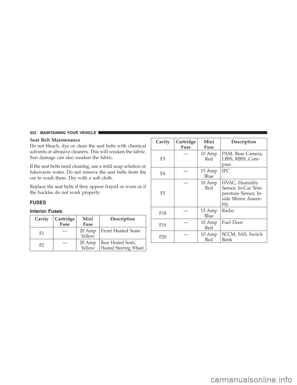
FUSES
Interior Fuses
Cavity CartridgeFuseMini
Fuse Description
F1 — 20 Amp
Yellow Front Heated Seats
F2 — 20 Amp
Yellow
Rear Heated Seats,
Heated Steering Wheel
Cavity Cartridge FuseMini
Fuse Description
F3 — 10 Amp
RedPAM, Rear Camera,
LBSS, RBSS, Com-
pass
F4 — 15 Amp
BlueIPC
F5 — 10 Amp
RedHVAC, Humidity
Sensor, In-Car Tem-
perature Sensor, In-
side Mirror Assem-
bly
F18 — 15 Amp
BlueRadio
F19 — 10 Amp
RedFuel Door
F20 — 10 Amp
RedSCCM, SAS, Switch
Bank
552 MAINTAINING YOUR VEHICLE
Page 555 of 604
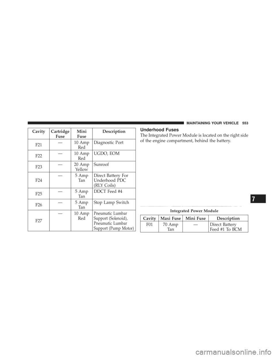
Cavity CartridgeFuseMini
Fuse Description
F21 — 10 Amp
RedDiagnostic Port
F22 — 10 Amp
RedUGDO, EOM
F23 — 20 Amp
Yellow Sunroof
F24 — 5 Amp
Ta nDirect Battery For
Underhood PDC
(RLY Coils)
F25 — 5 Amp
Ta nDDCT Feed #4
F26 — 5 Amp
Ta nStop Lamp Switch
F27 — 10 Amp
Red
Pneumatic Lumbar
Support (Solenoid),
Pneumatic Lumbar
Support (Pump Motor)
Underhood Fuses
The Integrated Power Module is located on the right side
of the engine compartment, behind the battery.
Cavity Maxi Fuse Mini Fuse Description
F01 70 Amp Ta n — Direct Battery
Feed #1 To BCM
Integrated Power Module
7
MAINTAINING YOUR VEHICLE 553
Page 556 of 604
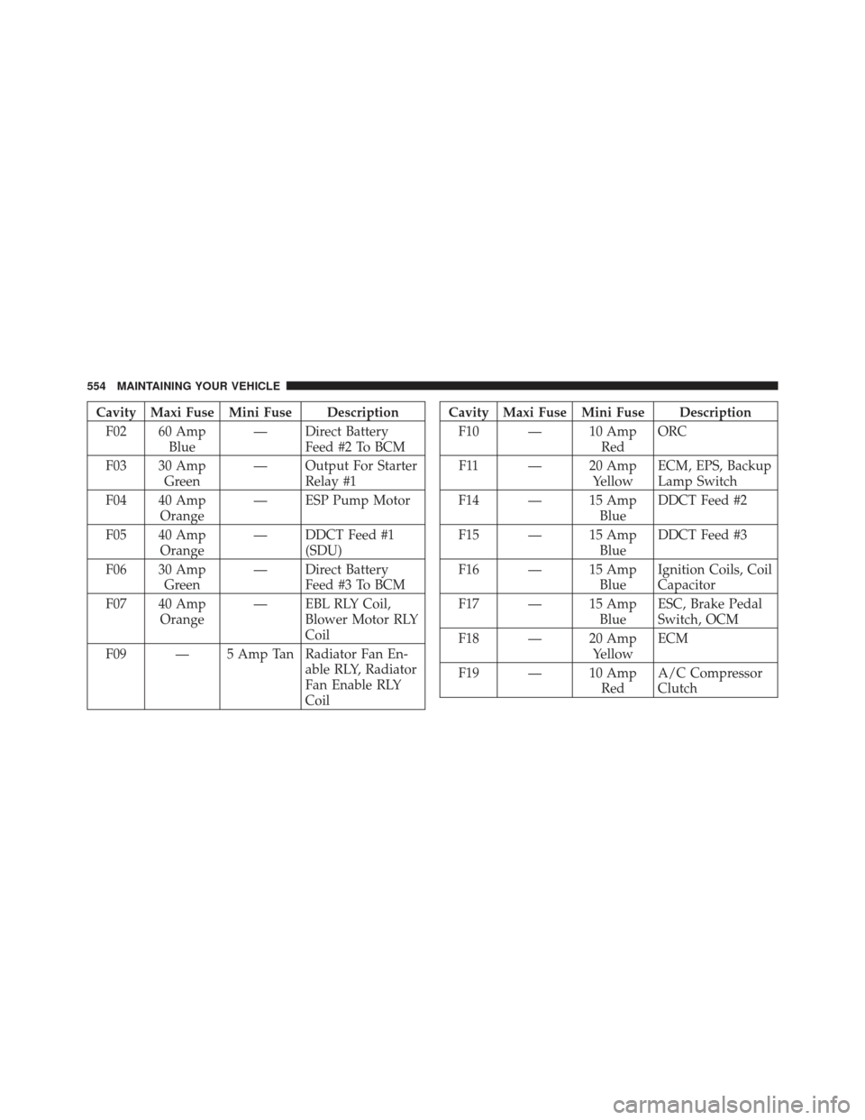
Cavity Maxi Fuse Mini Fuse DescriptionF02 60 Amp Blue — Direct Battery
Feed #2 To BCM
F03 30 Amp Green — Output For Starter
Relay #1
F04 40 Amp Orange — ESP Pump Motor
F05 40 Amp Orange — DDCT Feed #1
(SDU)
F06 30 Amp Green — Direct Battery
Feed #3 To BCM
F07 40 Amp Orange — EBL RLY Coil,
Blower Motor RLY
Coil
F09 — 5 Amp Tan Radiator Fan En- able RLY, Radiator
Fan Enable RLY
CoilCavity Maxi Fuse Mini Fuse Description
F10 — 10 Amp RedORC
F11 — 20 Amp YellowECM, EPS, Backup
Lamp Switch
F14 — 15 Amp BlueDDCT Feed #2
F15 — 15 Amp BlueDDCT Feed #3
F16 — 15 Amp BlueIgnition Coils, Coil
Capacitor
F17 — 15 Amp BlueESC, Brake Pedal
Switch, OCM
F18 — 20 Amp YellowECM
F19 — 10 Amp RedA/C Compressor
Clutch
554 MAINTAINING YOUR VEHICLE
Page 557 of 604
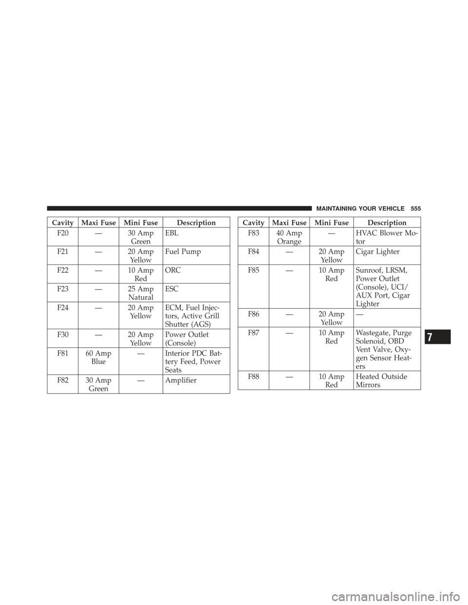
Cavity Maxi Fuse Mini Fuse DescriptionF20 — 30 Amp GreenEBL
F21 — 20 Amp YellowFuel Pump
F22 — 10 Amp RedORC
F23 — 25 Amp NaturalESC
F24 — 20 Amp YellowECM, Fuel Injec-
tors, Active Grill
Shutter (AGS)
F30 — 20 Amp YellowPower Outlet
(Console)
F81 60 Amp Blue — Interior PDC Bat-
tery Feed, Power
Seats
F82 30 Amp Green — AmplifierCavity Maxi Fuse Mini Fuse Description
F83 40 Amp Orange — HVAC Blower Mo-
tor
F84 — 20 Amp YellowCigar Lighter
F85 — 10 Amp RedSunroof, LRSM,
Power Outlet
(Console), UCI/
AUX Port, Cigar
Lighter
F86 — 20 Amp Yellow—
F87 — 10 Amp RedWastegate, Purge
Solenoid, OBD
Vent Valve, Oxy-
gen Sensor Heat-
ers
F88 — 10 Amp RedHeated Outside
Mirrors
7
MAINTAINING YOUR VEHICLE 555
Page 593 of 604
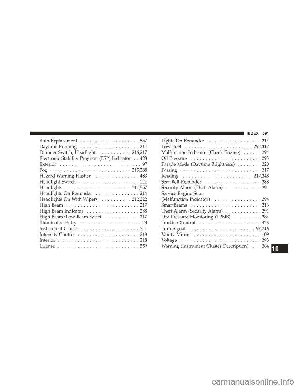
Bulb Replacement.................... 557
Daytime Running .................... 214
Dimmer Switch, Headlight ...........216,217
Electronic Stability Program (ESP) Indicator . . 423
Exterior ............................ 97
Fog ............................ 215,288
Hazard Warning Flasher ............... 483
Headlight Switch ..................... 211
Headlights ...................... 21 1,557
Headlights On Reminder ............... 214
Headlights On With Wipers ..........212,222
High Beam ......................... 217
High Beam Indicator .................. 288
High Beam/Low Beam Select ............ 217
Illuminated Entry ..................... 23
Instrument Cluster .................... 211
Intensity Control ..................... 218
Interior ............................ 218
License ............................ 559 Lights On Reminder
.................. 214
Low Fuel ....................... 292,312
Malfunction Indicator (Check Engine) ...... 294
Oil Pressure ........................ 293
Parade Mode (Daytime Brightness) ........ 220
Passing ............................ 217
Reading ........................ 217,248
Seat Belt Reminder ................... 288
Security Alarm (Theft Alarm) ............ 291
Service Engine Soon
(Malfunction Indicator) ................ 294
SmartBeams ........................ 213
Theft Alarm (Security Alarm) ............ 291
Tire Pressure Monitoring (TPMS) ......... 284
Traction Control ..................... 423
Turn Signal ....................... 97,216
Vanity Mirror ....................... 109
Voltage ............................ 293
Warning (Instrument Cluster Description) . . . 284
10
INDEX 591
Page 599 of 604
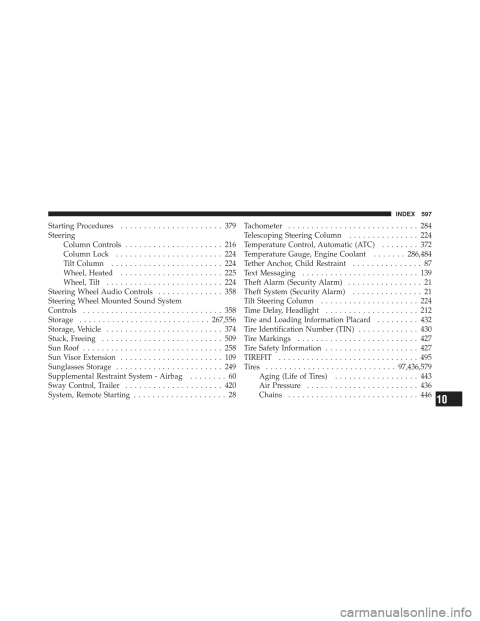
Starting Procedures...................... 379
Steering Column Controls ..................... 216
Column Lock ....................... 224
Tilt Column ........................ 224
Wheel, Heated ...................... 225
Wheel, Tilt ......................... 224
Steering Wheel Audio Controls .............. 358
Steering Wheel Mounted Sound System
Controls .............................. 358
Storage ............................ 267,556
Storage, Vehicle ......................... 374
Stuck, Freeing .......................... 509
Sun Roof .............................. 258
Sun Visor Extension ...................... 109
Sunglasses Storage ....................... 249
Supplemental Restraint System - Airbag ........ 60
Sway Control, Trailer ..................... 420
System, Remote Starting .................... 28 Tachometer
............................ 284
Telescoping Steering Column ............... 224
Temperature Control, Automatic (ATC) ........ 372
Temperature Gauge, Engine Coolant .......286,484
Tether Anchor, Child Restraint ............... 87
Text Messaging ......................... 139
Theft Alarm (Security Alarm) ................ 21
Theft System (Security Alarm) ............... 21
Tilt Steering Column ..................... 224
Time Delay, Headlight .................... 212
Tire and Loading Information Placard ......... 432
Tire Identification Number (TIN) ............. 430
Tire Markings .......................... 427
Tire Safety Information .................... 427
TIREFIT .............................. 495
Tires ............................ 97,436,579
Aging (Life of Tires) .................. 443
Air Pressure ........................ 436
Chains ............................ 446
10
INDEX 597