change time DODGE DART 2013 PF / 1.G Owner's Manual
[x] Cancel search | Manufacturer: DODGE, Model Year: 2013, Model line: DART, Model: DODGE DART 2013 PF / 1.GPages: 132, PDF Size: 4.13 MB
Page 57 of 132
NOTE:
When connecting your MP3 Player device for the first time, the system may take several
minutes to read your music, depending on the number of files. For example, the system
will take approximately five minutes for every 1000 songs loaded on the device. Also dur-
ing the reading process, the Shuffle and Browse functions will be disabled. This process
is needed to ensure the full use of your MP3 Player features and only happens the first
time it is connected. After the first time, the reading process of your MP3 Player will take
considerably less time unless changes are made or new songs are added to the playlist.
• The USB port supports certain Mini, Classic, Nano, Touch, and iPhone® devices. The USBport also supports playing music from compatible external USB Mass Storage Class
memory devices. Some iPod® software versions may not fully support the USB port
features. Please visit Apple’s website for iPod® software updates.
Audio Jack
• The Audio Jack allows a portable device, such as an MP3 player or an iPod® to be pluggedinto the radio and utilize the vehicle’s sound system, using a standard 3.5 mm audio
cable, to amplify the source and play through the vehicle speakers.
• Touch the Player soft-key on the then choose AUX source will change the mode to auxiliary device if the Audio Jack is connected, allowing the music from your portable
device to be heard through the vehicle's speakers.
• The functions of the portable device are controlled using the device controls. The volume may be controlled using the radio or portable device.
• To route the audio cable out of the center console, use the access cut out on the right side of the console.
Remote CD/Disc Player
• The CD/Disc Player is located inside the center console.
• With the printed side facing the rear of the car, lift up the protective door and insert thedisc into the disc slot. The radio pulls the disc in automatically. The radio selects the
appropriate mode after the disc is recognized, and starts playing the first track.
• The CD/Disc can also be selected by touching the Player soft-key, then touch the source soft-key and then touch the Disc soft-key.
NOTE: • Depending on the CD/Disc being used, you will only be able to browse by folder.
• There are Voice Commands available while in this mode. Refer to the Uconnect® VoiceCommand section in this guide.
ELECTRONICS
55
Page 74 of 132
Compass Calibration
• This compass is self-calibrating, which eliminates the need to set the compass manu-ally. When the vehicle is new, the compass may appear erratic and the EVIC will display
“CAL” until the compass is calibrated.
• You may also calibrate the compass by completing one or more 360 degree turns (in an area free from large metal or metallic objects) until the “CAL” message displayed in the
EVIC turns off. The compass will now function normally.
Programmable Features
• The EVIC can be used to view or change the following settings. Press the UP
or DOWN
button until System Setup displays, then press the RIGHTbutton. Scroll through
the settings using the UP or DOWN buttons. Press the RIGHT
button to change the
setting. Press the LEFT
button to scroll back to a previous menu or sub menu.
• Radio Info • Trip Info
• Fuel Economy Info • Tire Pressure
• Cruise Control Info • Vehicle Info
• Digital Vehicle Speed • Stored Warning Messages
• Analog Vehicle Speed • Turn Menu OFF
EVIC Selectable Menu Items
• The following items can be selected in the EVIC menu.
Full Speedometer Analog Or Digital Display
•Full Speedometer Analog Display Icon.
•
Full Speedometer Digital Display Icon.
• Press and release the UP
orDOWN button until the Analog or Digital display icon
is highlighted in the EVIC. Press and release the RIGHT
button to change the display
between analog and digital.
Vehicle Speed MPH/Km/h
• Press and release the UPorDOWN button until the Vehicle Speed icon is
highlighted in the EVIC. Press the RIGHT
button to view a digital display of the current
speed in MPH or km/h. Pressing the RIGHT
button a second time will toggle the unit
of measure between mph or km/h. Press the LEFT
button to return to the main menu.
ELECTRONICS
72
Page 76 of 132
Screen Setup
• Press and release the UPor DOWNbutton until the Screen Setup display icon
is highlighted in the EVIC. Press and release the RIGHT
button to enter the Screen
Setup sub-menu. The Screen Setup feature allows you to change what information is
displayed in the instrument cluster as well as the location that information is displayed.
• Press and release the UP
or DOWNbutton until the Screen Setup display icon
is highlighted in the EVIC. Press and release the RIGHT
button to enter the Screen
Setup sub-menu. The Screen Setup feature allows you to change the location that
information is displayed within the instrument cluster. Use the UP and DOWN buttons to
highlight a screen setup location (i.e., Upper Left, Upper Right, etc.) then press the RIGHT
arrow button to select the location and make changes. Press the UP and DOWN buttons
to select the information you would like to display in that location (i.e., Date, Time,
Outside Temp, etc.) and press the RIGHT arrow button to save the display setting. You can
press the LEFT arrow button at any time to back out of a sub-menu selection.
NOTE:
This option is only available when the vehicle is in the Park position.
Driver Selectable Items
Speedometer • Analog 1
• Analog 2
• Digital 1 (default setting)
• Digital 2
Gear Display • Standard (PRND –/+) (default setting)
• Single Character (D)
• Word (Drive)
Upper Left • None
• Compass
• Outside Temp (default setting)
• Date
• Time
• Distance To Empty (DTE)
• Average MPG
• Current MPG
• Trip A
• Trip B
ELECTRONICS
74
Page 78 of 132
UNIVERSAL GARAGE DOOR OPENER (HomeLink®)
• HomeLink® replaces up to three hand-held transmitters that operate devices such asgarage door openers, motorized gates, lighting or home security systems. The
HomeLink® unit is powered by your vehicles 12 Volt battery.
• The HomeLink® buttons that are located in the overhead console or sunvisor designate the three different HomeLink® channels.
• The HomeLink® indicator is located above the center button.
Before You Begin Programming
HomeLink®
• Ensure that your vehicle is parked outside of the garage before you begin program-
ming.
• For efficient programming and accurate transmission of the radio-frequency sig-
nal, it is recommended that a new battery
be placed in the hand-held transmitter of
the device that is being programmed to
the HomeLink® system.
• Erase all channels before you begin programming. To erase the channels, place the ignition switch into the ON/RUN position, then press and hold the two outside
HomeLink® buttons (I and III) for up to 20 seconds or until the red indicator flashes.
NOTE:
Erasing all channels should only be performed when programming HomeLink® for the first
time. Do not erase channels when programming additional buttons.
• If you have any problems, or require assistance, please call toll-free 1–800–355–3515 or, on the Internet at www.HomeLink.com for information or assistance.
Programming A Rolling Code
• For programming Garage Door Openers that were manufactured after 1995. These Garage Door Openers can be identified by the “LEARN” or “TRAIN” button located where
the hanging antenna is attached to the Garage Door Opener. It is NOT the button that is
normally used to open and close the door. The name and color of the button may vary by
manufacturer.
• Place the ignition switch into the ON/RUN position.
• Place the hand-held transmitter 1 to 3 in (3 to 8 cm) away from the HomeLink® button you wish to program while keeping the HomeLink® indicator light in view.
• Simultaneously press and hold both the HomeLink® button you want to program and the hand-held transmitter button.
• Continue to hold both buttons and observe the indicator light. The Homelink® indicator will flash slowly and then rapidly after Homelink® has received the frequency signal from
the hand-held transmitter. Release both buttons after the indicator light changes from
slow to rapid.
ELECTRONICS
76
Page 79 of 132
• At the garage door opener motor (in the garage), locate the “LEARN” or “TRAINING”button. This can usually be found where the hanging antenna wire is attached to the
garage door opener motor. Firmly press and release the “LEARN” or “TRAINING” button.
NOTE:
You have 30 seconds in which to initiate the next step after the LEARN button has been
pressed.
• Return to the vehicle and press the programmed HomeLink® button twice (holding the button for two seconds each time). If the device is plugged in and activates, program-
ming is complete.
NOTE:
If the device does not activate, press the button a third time (for two seconds) to complete
the training.
• To program the remaining two HomeLink® buttons, repeat each step for each remaining button. DO NOT erase the channels.
Programming A Non-Rolling Code
• For programming Garage Door Openers manufactured before 1995.
• Turn the ignition switch to the ON/RUN position.
• Place the hand-held transmitter 1 to 3 in (3 to 8 cm) away from the HomeLink® button you wish to program while keeping the HomeLink® indicator light in view.
• Simultaneously press and hold both the HomeLink® button you want to program and the hand-held transmitter button.
• Continue to hold both buttons and observe the indicator light. The Homelink® indicator will flash slowly and then rapidly after Homelink® has received the frequency signal from
the hand-held transmitter. Release both buttons after the indicator light changes from
slow to rapid.
• Press and hold the programmed HomeLink® button and observe the indicator light.
NOTE:
• If the indicator light stays on constantly, programming is complete and the garagedoor (or device) should activate when the HomeLink® button is pressed.
• To program the two remaining HomeLink® buttons, repeat each step for each remain- ing button. DO NOT erase the channels.
Using HomeLink®
• To operate, press and release the programmed HomeLink® button. Activation will now occur for the programmed device (i.e., garage door opener, gate operator, security
system, entry door lock, home/office lighting, etc.,). The hand-held transmitter of the
device may also be used at any time.
ELECTRONICS
77
Page 83 of 132
• Your vehicle has also been equipped with a TPMS malfunction indicator to indicate whenthe system is not operating properly. The TPMS malfunction indicator is combined with
the low tire pressure telltale. When the system detects a malfunction, the telltale will
flash for approximately one minute and then remain continuously illuminated. This
sequence will continue each time the vehicle is restarted as long as the malfunction
exists.
• When the malfunction indicator is illuminated, the system may not be able to detect or signal low tire pressure as intended. TPMS malfunctions may occur for a variety of
reasons, including the installation of replacement or alternate tires or wheels on the
vehicle that prevent the TPMS from functioning properly. Always check the TPMS mal-
function telltale after replacing one or more tires or wheels on your vehicle, to ensure that
the replacement or alternate tires and wheels allow the TPMS to continue to function
properly.
NOTE:
Tire pressures change by approximately 1 psi (7 kPa) per 12° F (7° C) of air temperature
change. Keep this in mind when checking tire pressure inside a garage, especially in the
Winter. Example: If garage temperature is 68°F (20°C) and the outside temperature is 32°F
(0°C), then the cold tire inflation pressure should be increased by 3 psi (21 kPa), which equals
1 psi (7 kPa) for every 12°F (7°C) for this outside temperature condition.
CAUTION!
The TPMS has been optimized for the original equipment tires and wheels. TPMS
pressures and warning have been established for the tire size equipped on your vehicle.
Undesirable system operation or sensor damage may result when using replacement
equipment that is not of the same size, type, and/or style. Aftermarket wheels can cause
sensor damage. Do not use tire sealant from a can, or balance beads if your vehicle is
equipped with a TPMS, as damage to the sensors may result.
- Engine Temperature Warning Light
• This light warns of an overheated engine condition.
• If the light turns on or flashes continuously while driving, safely pull over and stop the vehicle. If the A/C system is on, turn it off. Also, shift the transmission into NEUTRAL and
idle the vehicle. If the temperature reading does not return to normal, turn the engine off
immediately.
• We recommend that you do not operate the vehicle or engine damage will occur. Have the vehicle serviced immediately.
WARNING!
A hot engine cooling system is dangerous. You or others could be badly burned by steam
or boiling coolant.
WHAT TO DO IN EMERGENCIES
81
Page 85 of 132
- Anti-Lock Brake (ABS) Light
• This light monitors the Anti-Lock Brake System (ABS).
• If the light is not on during starting, stays on, or turns on while driving, we recommend you drive to the nearest authorized dealer immediately and have the vehicle serviced
immediately.
- Electronic Throttle Control (ETC) Indicator Light
• This light informs you of a problem with the system.
• If a problem is detected, the light will come on while the engine is running. Cycle the ignition when the vehicle has completely stopped and the shift lever is placed in the
PARK position; the light should turn off.
• If the light remains lit with the engine running, your vehicle will usually be drivable; however, see an authorized dealer immediately. If the light is flashing when the engine is
running, immediate service is required and you may experience reduced performance,
an elevated/rough idle or engine stall and your vehicle may require towing.
- Air Bag Warning Light
• If the light is not on during starting, stays on, or turns on while driving, have the vehicle serviced by an authorized dealer immediately.
Fuel Cap/Loose Gas Cap Message
• If a “gas cap” message (shown as gASCAP) appears, tighten the gas cap until a “clicking” sound is heard.
• Press the odometer reset button to turn the message off.
• If the message continues to appear for more than three days after tightening the gas cap, see your authorized service center.
Oil Change Indicator
• Your vehicle is equipped with an engine oil change indicator system. The “Oil Change Due” message will flash in the EVIC display for approximately 10 seconds after a single
chime has sounded, to indicate the next scheduled oil change interval. The engine oil
change indicator system is duty cycle based, which means the engine oil change interval
may fluctuate, dependent upon your personal driving style
• Unless reset, this message will continue to display each time you turn the ignition switch to the ON/RUN position or cycle the ignition to the ON/RUN position if equipped with
Keyless Enter-N-Go™. To turn off the message temporarily, press and release the MENU
button. To reset the oil change indicator system (after performing the scheduled main-
tenance) refer to the following procedure.
WHAT TO DO IN EMERGENCIES
83
Page 86 of 132

Vehicles Equipped With Keyless Enter-N-Go™
1. Without pressing the brake pedal, cycle the ignition to the ON/RUN position (do not startthe engine).
2. Fully depress the accelerator pedal, slowly, three times within 10 seconds.
3. Cycle the ignition to the OFF/LOCK position.
Vehicles Not Equipped With Keyless Enter-N-Go™
1. Turn the ignition switch to the ON/RUN position (do not start the engine).
2. Fully depress the accelerator pedal, slowly, three times within 10 seconds.
3. Turn the ignition switch to the OFF/LOCK position.
NOTE:
If the indicator message illuminates when you start the vehicle, the oil change indicator
system did not reset. If necessary, repeat this procedure.
Resetting The Light After Servicing
• Vehicles Equipped With Keyless Enter-N-Go™
• Without pressing the brake pedal, push the ENGINE START/STOP button and cycle the ignition to the ON/RUN position (Do not start the engine.)
• Fully depress the accelerator pedal, slowly, three times within 10 seconds.
• Without pressing the brake pedal, push the ENGINE START/STOP button once to return the ignition to the OFF/LOCK position.
• Vehicles Not Equipped With Keyless Enter-N-Go™
• Turn the ignition switch to the ON/RUN position (Do not start the engine.)
• Fully depress the accelerator pedal, slowly, three times within 10 seconds.
• Turn the ignition switch to the OFF/LOCK position.
WHAT TO DO IN EMERGENCIES
84
Page 112 of 132
CAUTION!
• Mixing of engine coolant (antifreeze) other than specified Organic Additive Technol-ogy (OAT) engine coolant (antifreeze), may result in engine damage and may de-
crease corrosion protection. Organic Additive Technology (OAT) engine coolant is
different and should not be mixed with Hybrid Organic Additive Technology (HOAT)
engine coolant (antifreeze) or any “globally compatible” coolant (antifreeze). If a
non-OAT engine coolant (antifreeze) is introduced into the cooling system in an
emergency, the cooling system will need to be drained, flushed, and refilled with
fresh OAT coolant (conforming to MS-12106), by an authorized dealer as soon as
possible.
• Do not use water alone or alcohol-based engine coolant (antifreeze) products. Do not
use additional rust inhibitors or antirust products, as they may not be compatible
with the radiator engine coolant and may plug the radiator.
• This vehicle has not been designed for use with propylene glycol-based engine
coolant (antifreeze). Use of propylene glycol-based engine coolant (antifreeze) is not
recommended.
MAINTENANCE SCHEDULE
Your vehicle is equipped with an automatic oil change indicator system. The oil change
indicator system will remind you that it is time to take your vehicle in for scheduled
maintenance.
Based on engine operation conditions, the oil change indicator message will illuminate.
This means that service is required for your vehicle. Operating conditions such as frequent
short-trips, trailer tow, extremely hot or cold ambient temperatures, and E85 fuel usage will
influence when the “Change Oil” or “Oil Change Required” message is displayed. Severe
Operating Conditions can cause the change oil message to illuminate as early as 3,500
miles (5,600 km) since last reset. Have your vehicle serviced as soon as possible, within the
next 500 miles (805 km).
NOTE:
Under no circumstances should oil change intervals exceed 10,000 miles (16,000 km) or
twelve months, whichever comes first.
MAINTAINING YOUR VEHICLE
110
Page 114 of 132
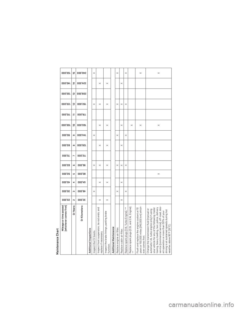
Maintenance Chart
Mileage or time passed
(whichever comes first)
20,000
30,000
40,000
50,000
60,000
70,000
80,000 90,000
100,000
110,000
120,000 130,000
140,000
150,000
Or Years: 2 3 4 5 6 7 8 9 10 11 12 13 14 15
Or Kilometers:
32,000
48,000
64,000
80,000
96,000
112,000
128,000 144,000
160,000
176,000
192,000
208,000
224,000
240,000
Additional Inspections
Inspect the CV boots. X X X X X
Inspect front suspension, tie rod ends, and
replace if necessary. XXX X X X X
Inspect the brake linings, parking brake
function. XXX X X X X
Additional Maintenance
Replace engine air filter. X X X X X
Replace cabin air filter. X X X X X X X
Replace spark plugs (1.4L Turbo Engine). ** X X X X X
Replace spark plugs (2.0L and 2.4L Engine).
** X
Flush and replace the engine coolant at 10
years or 150,000 miles (240,000 km) which-
ever comes first. XX
Change the transmission fluid (manual or
automatic 1.4L turbo engine only) if using
your vehicle for any of the following: trailer
towing, heavy loading, taxi, police, delivery
service (commercial service), off-road, des-
ert operation or more than 50% of your
driving is at sustained speeds during hot
weather, above 90°F (32°C). XX X
MAINTAINING YOUR VEHICLE
112