radio DODGE DART 2013 PF / 1.G Owner's Manual
[x] Cancel search | Manufacturer: DODGE, Model Year: 2013, Model line: DART, Model: DODGE DART 2013 PF / 1.GPages: 132, PDF Size: 4.13 MB
Page 67 of 132
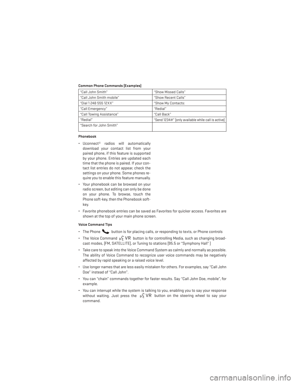
Common Phone Commands (Examples)
“Call John Smith”“Show Missed Calls”
“Call John Smith mobile” “Show Recent Calls”
“Dial 1 248 555 12XX” “Show My Contacts:
“Call Emergency” “Redial”
“Call Towing Assistance” “Call Back”
“Redial”
“Send 1234#” (only available while call is active)
“Search for John Smith”
Phonebook
• Uconnect® radios will automatically download your contact list from your
paired phone, if this feature is supported
by your phone. Entries are updated each
time that the phone is paired. If your con-
tact list entries do not appear, check the
settings on your phone. Some phones re-
quire you to enable this feature manually.
• Your phonebook can be browsed on your radio screen, but editing can only be done
on your phone. To browse, touch the
Phone soft-key, then the Phonebook soft-
key.
• Favorite phonebook entries can be saved as Favorites for quicker access. Favorites are shown at the top of your main phone screen.
Voice Command Tips
• The Phonebutton is for placing calls, or responding to texts, or Phone controls
• The Voice Command
button is for controlling Media, such as changing broad-
cast modes, (FM, SATELLITE), or Tuning to stations (95.5 or “Symphony Hall” )
• Take care to speak into the Voice Command System as calmly and normally as possible. The ability of Voice Command to recognize user voice commands may be negatively
affected by rapid speaking or a raised voice level.
• Use longer names that are less easily mistaken for others. For examples, say “Call John Doe” instead of “Call John”.
• You can “chain” commands together for faster results. Say “Call John Doe, mobile”, for example.
• You can interrupt while the system is talking to you, enabling you to say your response without waiting. Just press the
button on the steering wheel to say your
command.
ELECTRONICS
65
Page 68 of 132
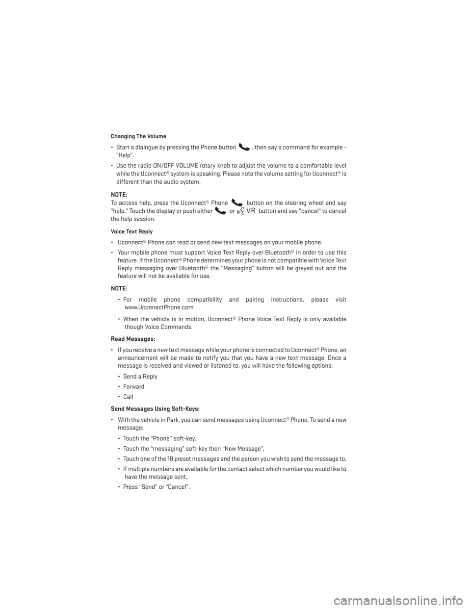
Changing The Volume
• Start a dialogue by pressing the Phone button, then say a command for example -
"Help".
• Use the radio ON/OFF VOLUME rotary knob to adjust the volume to a comfortable level while the Uconnect® system is speaking. Please note the volume setting for Uconnect® is
different than the audio system.
NOTE:
To access help, press the Uconnect® Phone
button on the steering wheel and say
"help." Touch the display or push either
orbutton and say "cancel" to cancel
the help session.
Voice Text Reply
• Uconnect® Phone can read or send new text messages on your mobile phone.
• Your mobile phone must support Voice Text Reply over Bluetooth® in order to use this feature. If the Uconnect® Phone determines your phone is not compatible with Voice Text
Reply messaging over Bluetooth® the “Messaging” button will be greyed out and the
feature will not be available for use.
NOTE: • For mobile phone compatibility and pairing instructions, please visitwww.UconnectPhone.com
• When the vehicle is in motion, Uconnect® Phone Voice Text Reply is only available though Voice Commands.
Read Messages:
• If you receive a new text message while your phone is connected to Uconnect® Phone, an announcement will be made to notify you that you have a new text message. Once a
message is received and viewed or listened to, you will have the following options:
• Send a Reply
•Forward
• Call
Send Messages Using Soft-Keys:
• With the vehicle in Park, you can send messages using Uconnect® Phone. To send a new message:
• Touch the “Phone” soft-key,
• Touch the “messaging” soft-key then “New Message”,
• Touch one of the 18 preset messages and the person you wish to send the message to,
• If multiple numbers are available for the contact select which number you would like tohave the message sent,
• Press “Send” or “Cancel”.
ELECTRONICS
66
Page 69 of 132
Send Messages Using Voice Commands:
• Press the Uconnect® Phone
button,
• After the “Listening” prompt and the following beep, say “Send message to John Smith mobile”,
• After the system prompts you for what message you want to send, say the message you wish to send or say “List”. There are 18 preset messages.
• While the list of defined messages are being read, you can interrupt the system by pressing the
button and saying the message you want to send.
• After the system confirms that you want to send your message to John Smith, your message will be sent.
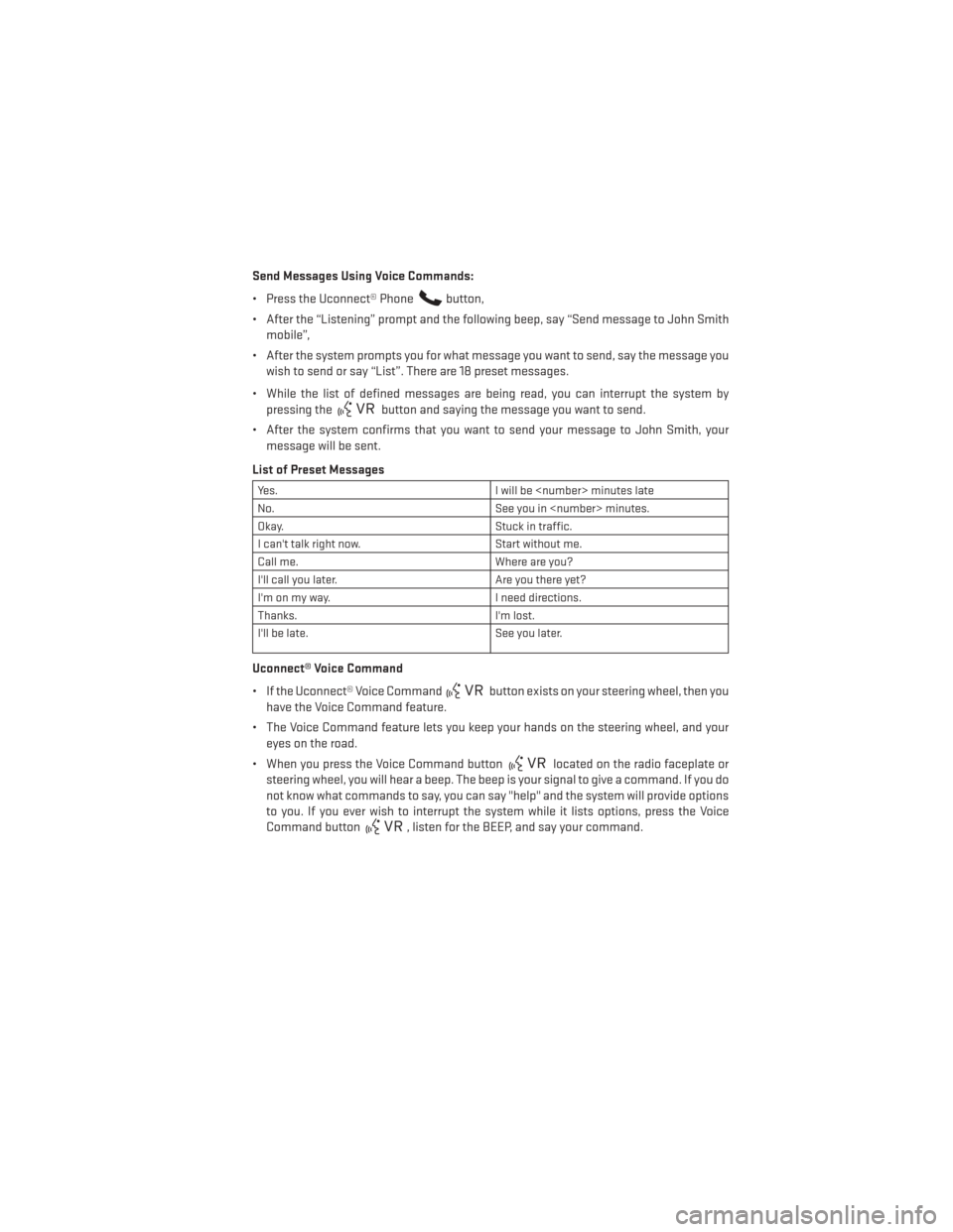
List of Preset Messages
Yes. I will be
No. See you in
Okay. Stuck in traffic.
I can't talk right now. Start without me.
Call me. Where are you?
I'll call you later. Are you there yet?
I'm on my way. I need directions.
Thanks. I'm lost.
I'll be late. See you later.
Uconnect® Voice Command
• If the Uconnect® Voice Command
button exists on your steering wheel, then you
have the Voice Command feature.
• The Voice Command feature lets you keep your hands on the steering wheel, and your eyes on the road.
• When you press the Voice Command button
located on the radio faceplate or
steering wheel, you will hear a beep. The beep is your signal to give a command. If you do
not know what commands to say, you can say "help" and the system will provide options
to you. If you ever wish to interrupt the system while it lists options, press the Voice
Command button
, listen for the BEEP, and say your command.
ELECTRONICS
67
Page 70 of 132
Changing The Volume
• Start a dialogue by pressing the Phone button, then say a command for example -
"Help".
• Use the radio ON/OFF VOLUME rotary knob to adjust the volume to a comfortable level while the Uconnect® system is speaking. Please note the volume setting for Uconnect® is
different than the audio system.
NOTE:
To access help, press the Uconnect® Phone
button on the steering wheel and say
"help." Touch the display or push either
orbutton and say "cancel" to cancel
the help session.
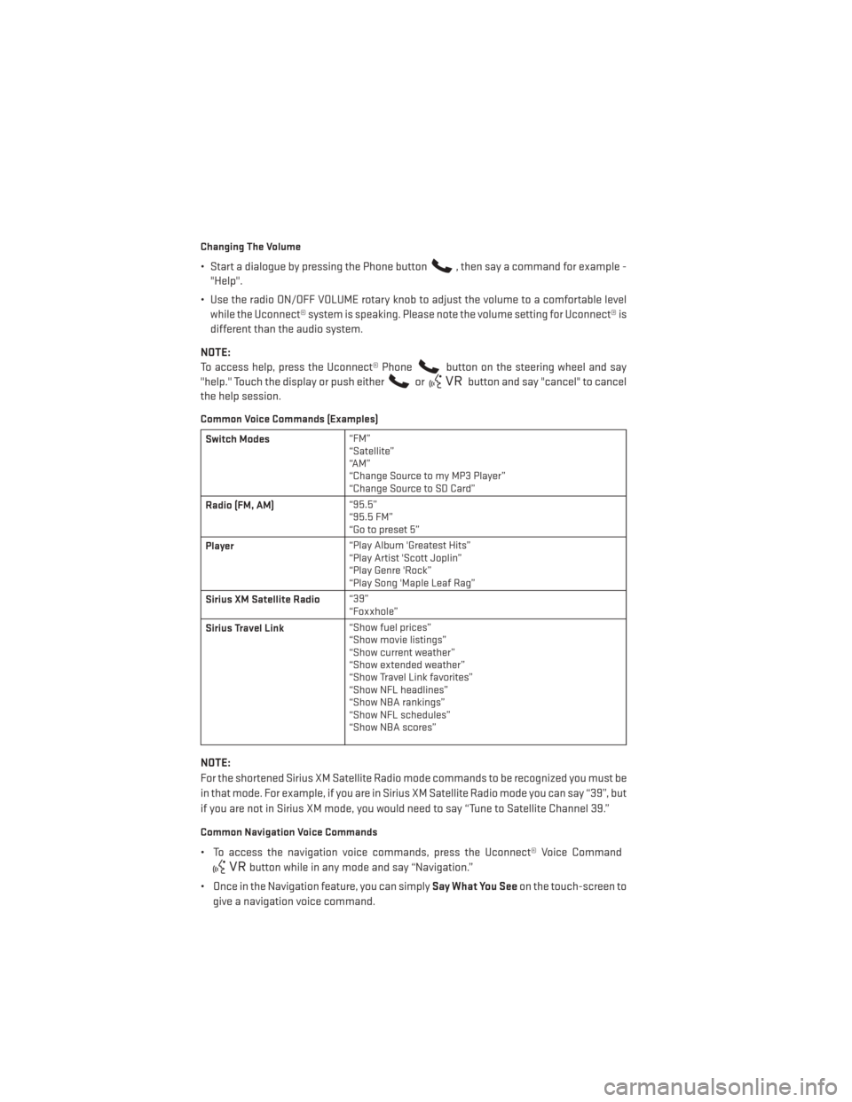
Common Voice Commands (Examples)
Switch Modes “FM”
“Satellite”
“AM”
“Change Source to my MP3 Player”
“Change Source to SD Card”
Radio (FM, AM) “95.5”
“95.5 FM”
“Go to preset 5”
Player “Play Album 'Greatest Hits”
“Play Artist 'Scott Joplin”
“Play Genre 'Rock”
“Play Song 'Maple Leaf Rag”
Sirius XM Satellite Radio “39”
“Foxxhole”
Sirius Travel Link “Show fuel prices”
“Show movie listings”
“Show current weather”
“Show extended weather”
“Show Travel Link favorites”
“Show NFL headlines”
“Show NBA rankings”
“Show NFL schedules”
“Show NBA scores”
NOTE:
For the shortened Sirius XM Satellite Radio mode commands to be recognized you must be
in that mode. For example, if you are in Sirius XM Satellite Radio mode you can say “39”, but
if you are not in Sirius XM mode, you would need to say “Tune to Satellite Channel 39.”
Common Navigation Voice Commands
• To access the navigation voice commands, press the Uconnect® Voice Command
button while in any mode and say “Navigation.”
• Once in the Navigation feature, you can simply Say What You Seeon the touch-screen to
give a navigation voice command.
ELECTRONICS
68
Page 72 of 132
STEERING WHEEL AUDIO CONTROLS
• The steering wheel audio controls are lo-cated on the rear surface of the steering
wheel.
Right Switch
• Press the switch up or down to increase or decrease the volume.
• Press the button in the center to change modes AM/FM/CD/SXM.
Left Switch
• Press the switch up or down to search for the next listenable station or select the next or previous CD track.
• Press the button in the center to select the next preset station (radio) or to change CDs if equipped with a CD Changer.
ELECTRONIC VEHICLE INFORMATION CENTER (EVIC) –
STANDARD (2 BUTTON)
• The EVIC features a driver interactive dis-play that is located in the instrument
cluster. Pressing the controls on the left
side of the steering wheel allows the
driver to select vehicle information/
personal settings. For additional informa-
tion, refer to Programmable Features in
this section.
• Press and release the UP
button to
scroll upward through the main menus
(Odometer, Digital Vehicle Speed, Trip
Info, Range To Empty, Average Fuel
Economy, Current Fuel Economy, Stored Messages, Settings).
• Press and release the SELECT
button to access the sub-menu screens of a main
menu item. Press and hold the RIGHT arrow button for two seconds to reset displayed/
selected features that can be reset.
ELECTRONICS
70
Page 74 of 132
Compass Calibration
• This compass is self-calibrating, which eliminates the need to set the compass manu-ally. When the vehicle is new, the compass may appear erratic and the EVIC will display
“CAL” until the compass is calibrated.
• You may also calibrate the compass by completing one or more 360 degree turns (in an area free from large metal or metallic objects) until the “CAL” message displayed in the
EVIC turns off. The compass will now function normally.
Programmable Features
• The EVIC can be used to view or change the following settings. Press the UP
or DOWN
button until System Setup displays, then press the RIGHTbutton. Scroll through
the settings using the UP or DOWN buttons. Press the RIGHT
button to change the
setting. Press the LEFT
button to scroll back to a previous menu or sub menu.
• Radio Info • Trip Info
• Fuel Economy Info • Tire Pressure
• Cruise Control Info • Vehicle Info
• Digital Vehicle Speed • Stored Warning Messages
• Analog Vehicle Speed • Turn Menu OFF
EVIC Selectable Menu Items
• The following items can be selected in the EVIC menu.
Full Speedometer Analog Or Digital Display
•Full Speedometer Analog Display Icon.
•
Full Speedometer Digital Display Icon.
• Press and release the UP
orDOWN button until the Analog or Digital display icon
is highlighted in the EVIC. Press and release the RIGHT
button to change the display
between analog and digital.
Vehicle Speed MPH/Km/h
• Press and release the UPorDOWN button until the Vehicle Speed icon is
highlighted in the EVIC. Press the RIGHT
button to view a digital display of the current
speed in MPH or km/h. Pressing the RIGHT
button a second time will toggle the unit
of measure between mph or km/h. Press the LEFT
button to return to the main menu.
ELECTRONICS
72
Page 78 of 132
UNIVERSAL GARAGE DOOR OPENER (HomeLink®)
• HomeLink® replaces up to three hand-held transmitters that operate devices such asgarage door openers, motorized gates, lighting or home security systems. The
HomeLink® unit is powered by your vehicles 12 Volt battery.
• The HomeLink® buttons that are located in the overhead console or sunvisor designate the three different HomeLink® channels.
• The HomeLink® indicator is located above the center button.
Before You Begin Programming
HomeLink®
• Ensure that your vehicle is parked outside of the garage before you begin program-
ming.
• For efficient programming and accurate transmission of the radio-frequency sig-
nal, it is recommended that a new battery
be placed in the hand-held transmitter of
the device that is being programmed to
the HomeLink® system.
• Erase all channels before you begin programming. To erase the channels, place the ignition switch into the ON/RUN position, then press and hold the two outside
HomeLink® buttons (I and III) for up to 20 seconds or until the red indicator flashes.
NOTE:
Erasing all channels should only be performed when programming HomeLink® for the first
time. Do not erase channels when programming additional buttons.
• If you have any problems, or require assistance, please call toll-free 1–800–355–3515 or, on the Internet at www.HomeLink.com for information or assistance.
Programming A Rolling Code
• For programming Garage Door Openers that were manufactured after 1995. These Garage Door Openers can be identified by the “LEARN” or “TRAIN” button located where
the hanging antenna is attached to the Garage Door Opener. It is NOT the button that is
normally used to open and close the door. The name and color of the button may vary by
manufacturer.
• Place the ignition switch into the ON/RUN position.
• Place the hand-held transmitter 1 to 3 in (3 to 8 cm) away from the HomeLink® button you wish to program while keeping the HomeLink® indicator light in view.
• Simultaneously press and hold both the HomeLink® button you want to program and the hand-held transmitter button.
• Continue to hold both buttons and observe the indicator light. The Homelink® indicator will flash slowly and then rapidly after Homelink® has received the frequency signal from
the hand-held transmitter. Release both buttons after the indicator light changes from
slow to rapid.
ELECTRONICS
76
Page 80 of 132
WARNING!
• Your motorized door or gate will open and close while you are programming theuniversal transceiver. Do not program the transceiver if people or pets are in the path
of the door or gate.
• Do not run your vehicle in a closed garage or confined area while programming the
transceiver. Exhaust gas from your vehicle contains Carbon Monoxide (CO) which is
odorless and colorless. Carbon Monoxide is poisonous when inhaled and can cause
you and others to be severely injured or killed.
POWER OUTLET
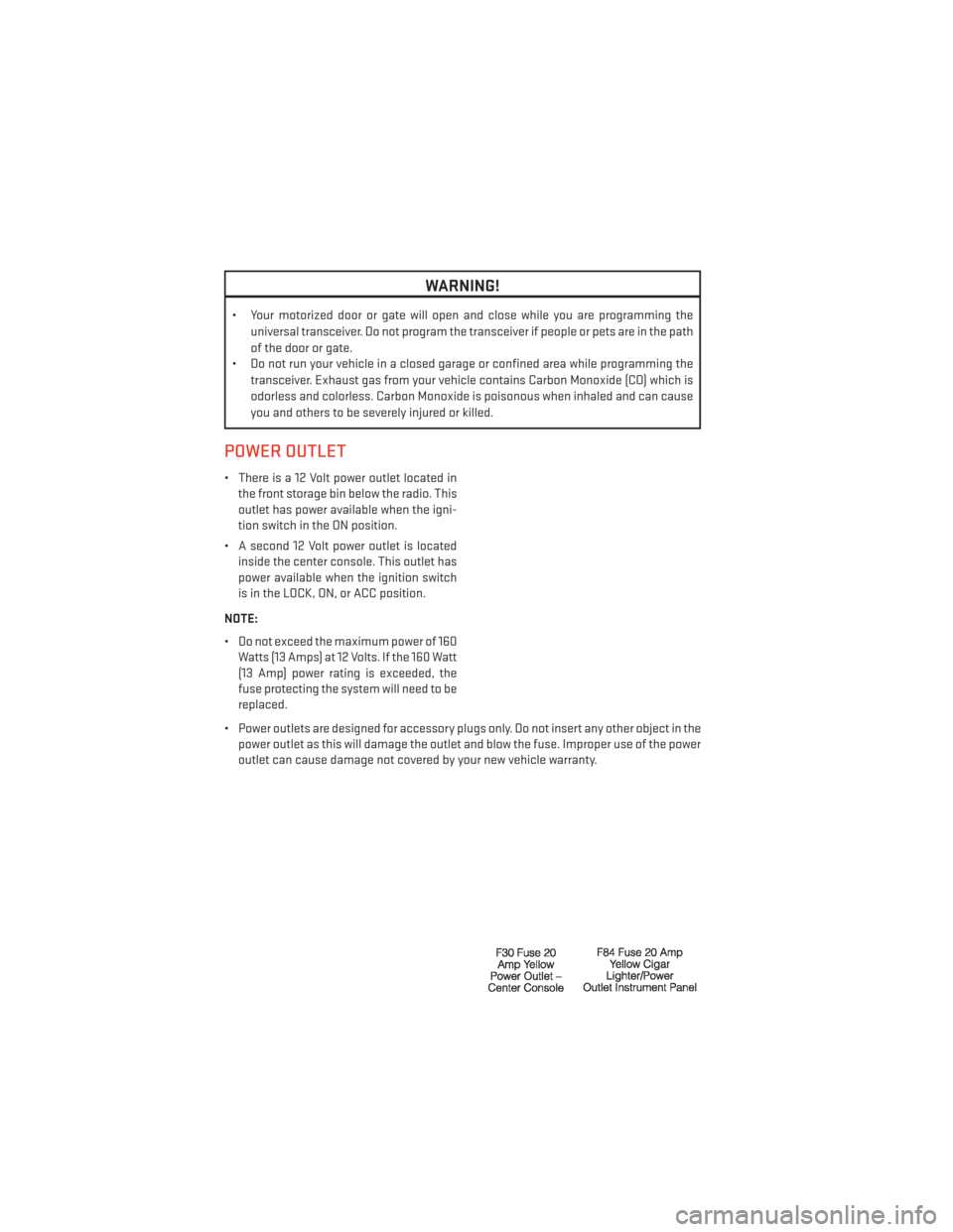
• There is a 12 Volt power outlet located inthe front storage bin below the radio. This
outlet has power available when the igni-
tion switch in the ON position.
• A second 12 Volt power outlet is located inside the center console. This outlet has
power available when the ignition switch
is in the LOCK, ON, or ACC position.
NOTE:
• Do not exceed the maximum power of 160 Watts (13 Amps) at 12 Volts. If the 160 Watt
(13 Amp) power rating is exceeded, the
fuse protecting the system will need to be
replaced.
• Power outlets are designed for accessory plugs only. Do not insert any other object in the power outlet as this will damage the outlet and blow the fuse. Improper use of the power
outlet can cause damage not covered by your new vehicle warranty.
ELECTRONICS
78
Page 100 of 132
JUMP-STARTING
• If your vehicle has a discharged battery itcan be jump-started using a set of jumper
cables and a battery in another vehicle or
by using a portable battery booster pack.
• Jump-starting can be dangerous if done improperly so please follow the proce-
dures in this section carefully.
NOTE:
When using a portable battery booster pack
follow the manufacturer’s operating instruc-
tions and precautions.
Preparations for Jump-Start
• The battery in your vehicle is located in the front of the engine compartment, be-
hind the left headlight assembly.
NOTE:
The positive battery post is covered with a protective cap. Lift up on the cap to gain access
to the positive battery post.
• Set the parking brake, shift the automatic transmission into PARK (manual transmission in NEUTRAL) and turn the ignition to LOCK.
• Turn off the heater, radio, and all unnecessary electrical accessories.
• If using another vehicle to jump-start the battery, park the vehicle within the jumper cables reach, set the parking brake and make sure the ignition is OFF.
Jump-Starting Procedure
1. Connect the positive (+) end of the jumper cable to the remote positive (+) post of the discharged vehicle.
2. Connect the opposite end of the positive (+) jumper cable to the positive (+) post of the booster battery.
3. Connect the negative end (-) of the jumper cable to the negative (-) post of the booster battery.
4. Connect the opposite end of the negative (-) jumper cable to the remote negative (-) post of the vehicle with the discharged battery.
5. Start the engine in the vehicle that has the booster battery, let the engine idle a few minutes, and then start the engine in the vehicle with the discharged battery.
Once the engine is started, remove the jumper cables in the reverse sequence:
1. Disconnect the negative (-) jumper cable from the remote negative (-) post of the vehicle with the discharged battery.
WHAT TO DO IN EMERGENCIES
98
Page 117 of 132
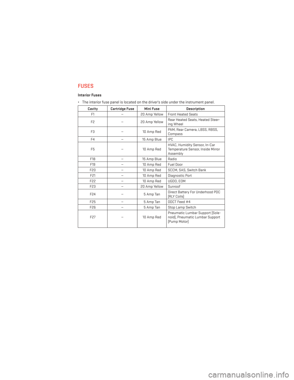
FUSES
Interior Fuses
• The interior fuse panel is located on the driver's side under the instrument panel.
Cavity Cartridge Fuse Mini FuseDescription
F1 — 20 Amp Yellow Front Heated Seats
F2 — 20 Amp Yellow Rear Heated Seats, Heated Steer-
ing Wheel
F3 — 10 Amp Red PAM, Rear Camera, LBSS, RBSS,
Compass
F4 — 15 Amp Blue IPC
F5 — 10 Amp Red HVAC, Humidity Sensor, In-Car
Temperature Sensor, Inside Mirror
Assembly
F18 — 15 Amp Blue Radio
F19 — 10 Amp Red Fuel Door
F20 — 10 Amp Red SCCM, SAS, Switch Bank
F21 — 10 Amp Red Diagnostic Port
F22 — 10 Amp Red UGDO, EOM
F23 — 20 Amp Yellow Sunroof
F24 —5 Amp Tan Direct Battery For Underhood PDC
(RLY Coils)
F25 —5 Amp Tan DDCT Feed #4
F26 —5 Amp Tan Stop Lamp Switch
F27 — 10 Amp Red Pneumatic Lumbar Support (Sole-
noid), Pneumatic Lumbar Support
(Pump Motor)
MAINTAINING YOUR VEHICLE
115