clock DODGE DART 2013 PF / 1.G User Guide
[x] Cancel search | Manufacturer: DODGE, Model Year: 2013, Model line: DART, Model: DODGE DART 2013 PF / 1.GPages: 132, PDF Size: 4.13 MB
Page 41 of 132
Clock Setting
• Press and hold the TIME button until the hours are highlighted.
• Adjust the hours by turning the right side TUNE/SCROLL control knob.
• After adjusting the hours, press the right side ENTER/BROWSE control knob to set theminutes. The minutes will highlight.
• Adjust the minutes using the right side TUNE/SCROLL control knob.
• To exit, press the TIME button or press the BACK button to return to the previous menu.
NOTE:
Time format has the options of 12HR or 24HR. Selecting one of these options will change
the way the clock is displayed.
Equalizer, Balance And Fade
• To set the Bass, Mid Range, Treble, Balance or Fade settings press the AUDIO button to access the Audio sub-menu.
• The Audio sub-menu can also be reached by pressing the MENU button until AUDIO appears in the display. Press the ENTER/BROWSE button to select the AUDIO menu and
use the TUNE/SCROLL knob to highlight select Bass, Mid Range, Treble, Balance or Fade.
Once the desired selection is highlighted, press the ENTER/BROWSE button to select the
item and use the TUNE/SCROLL knob to adjust the setting.
Radio Operation
RADIO Button
• Press the button to select either AM, FM or SiriusXM mode.
Seek Up/Down Buttons
• Press to seek through radio stations in AM, FM, or SXM bands.
• Hold either button to bypass stations without stopping.
Buttons1-5
• These buttons tune the radio to the stations that you commit to pushbutton memory AM (A, B, C), FM (A, B, C) and SXM (A,B,C) — 15 AM, 15 FM and 15 SXM stations.
Store Radio Presets
• When you are receiving a station that you wish to commit to pushbutton memory, pressand hold the button (1–5) you wish to lock onto this station for three seconds.
• You may add a second or third station to each pushbutton by repeating the above procedure with this exception: Press the A–B–C button to select the A, B or C mode. Each
button can be set for up to three stations in both AM and FM. This allows a total of 15 AM,
15 FM and 15 SXM stations to be stored into push-button memory.
ELECTRONICS
39
Page 42 of 132
INFO Button
• Press the INFO button for an RDS station (one with call letters displayed). The radio willreturn a Radio Text message broadcast from an FM station (FM mode only).
Player Button
• Pressing the Player button will allow you to switch from AM/FM/SXM modes to Playermode (AUX/CD/Bluetooth Steaming (BT)/USB).
MENU Button
• Pressing the MENU button allows you to scroll between the setting sub-menus. Once thedesired sub-menu setting is highlighted press the TUNE/SCROLL knob to select the
setting. The following items are selectable:
Radio Mode
• Audio — Selecting the Audio sub-menu will allow you to adjust the Bass, Mid Range,
Treble, Balance or Fade, just like pressing the Audio hard control. If the BACK button is
pressed the radio will return to the Main Menu.
• Clock — Selecting Clock will allow you to set the clock. Adjust the hours by turning the
TUNE/SCROLL control knob. After adjusting the hours, press the ENTER/BROWSE but-
ton to set the minutes. The minutes will highlight. Adjust the minutes using the right side
TUNE/SCROLL control knob. Press the ENTER/BROWSE button to save time change.
Player Mode
• Player Browse — Selecting Player Browse will go to the appropriate browse menu
depending on the device currently playing (will function the same as pressing the browse
button while in that mode). This will only appear in the menu if the device currently
playing can support these features.
• Shuffle (SHFL) — This function shuffles (randomizes the order of the files). This will only
appear in the menu if the device currently playing can support these features.
• Repeat (RPT) — When Repeat is activated, the currently playing song will begin again
when it ends. It will continue to cycle through the same song until repeat is turned Off.
Repeat will be turned off once one for the following conditions are met: 1) The source is
ejected 2) A different track list within that source is initiated 3) The REPEAT button is
toggled OFF. This will only appear in the menu if the device currently playing can support
these features.
• Audio — Selecting the Audio sub-menu will allow you to adjust the Bass, Mid Range,
Treble, Balance or Fade, just like pressing the Audio hard control. If the BACK button is
pressed the radio will return to the Main Menu.
• Clock — Selecting Clock will allow you to set the clock. Adjust the hours by turning the
right-side TUNE/SCROLL control knob. After adjusting the hours, press the ENTER/
BROWSE button to set the minutes. The minutes will highlight. Adjust the minutes using
the right side TUNE/SCROLL control knob. Press the ENTER/BROWSE button to save
time change.
ELECTRONICS
40
Page 50 of 132
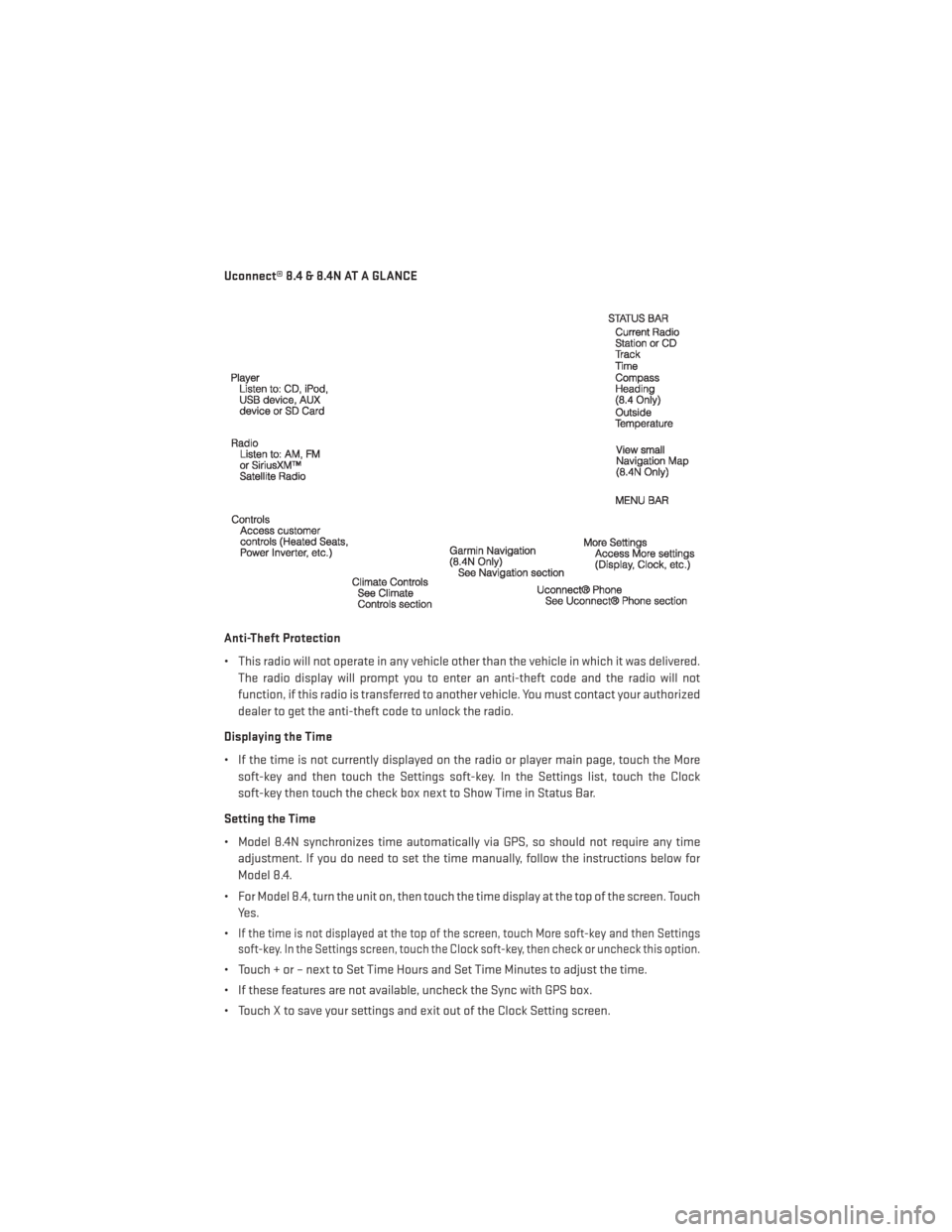
Uconnect® 8.4 & 8.4N AT A GLANCE
Anti-Theft Protection
• This radio will not operate in any vehicle other than the vehicle in which it was delivered.The radio display will prompt you to enter an anti-theft code and the radio will not
function, if this radio is transferred to another vehicle. You must contact your authorized
dealer to get the anti-theft code to unlock the radio.
Displaying the Time
• If the time is not currently displayed on the radio or player main page, touch the More soft-key and then touch the Settings soft-key. In the Settings list, touch the Clock
soft-key then touch the check box next to Show Time in Status Bar.
Setting the Time
• Model 8.4N synchronizes time automatically via GPS, so should not require any time adjustment. If you do need to set the time manually, follow the instructions below for
Model 8.4.
• For Model 8.4, turn the unit on, then touch the time display at the top of the screen. Touch Yes.
•
If the time is not displayed at the top of the screen, touch More soft-key and then Settings
soft-key. In the Settings screen, touch the Clock soft-key, then check or uncheck this option.
• Touch + or – next to Set Time Hours and Set Time Minutes to adjust the time.
• If these features are not available, uncheck the Sync with GPS box.
• Touch X to save your settings and exit out of the Clock Setting screen.
ELECTRONICS
48
Page 77 of 132
Upper Right• None
• Compass (default setting)
• Outside Temp
• Date
• Time
• Distance To Empty (DTE)
• Average MPG
• Current MPG
• Trip A
• Trip B
Lower Left • None
• Compass (default setting)
• Outside Temp
• Time
Lower Right • None
• Compass
• Outside Temp
• Time (default setting)
Restore To Defaults (Restores All Settings To
Default Settings) • Cancel
•Okay
Uconnect® 8.4 Customer Programmable Features
• The Uconnect® 8.4 system allows you to access Customer Programmable feature set-
tings such as Display, Clock, Safety/Assistance, Lights, Doors & Locks, Heated Seats,
Engine Off Operation, Compass Settings, Audio, Phone/ Bluetooth and SiriusXM Setup
through soft-keys.
• Touch the More soft-key on the bottom of the screen, then touch the Settings soft-key to access the Settings screen. When making a selection, scroll up or down until the
preferred setting is highlighted, then press and release the preferred setting until a
check-mark appears next to the setting, showing that setting has been selected. The
following feature settings are available:
• Display • Clock
• Safety / Assistance • Lights
• Doors & Locks • Auto-On Comfort & Remote Start
• Engine Off Options • Compass Settings
• Audio • Phone / Bluetooth
• SiriusXM Setup
ELECTRONICS
75
Page 89 of 132
Preparations For Jacking
1. Park the vehicle on a firm, level surface as far from the edge of the roadway as possible.Avoid icy or slippery areas.
2. Turn on the Hazard Warning flasher.
3. Set the parking brake.
4. Place the shift lever into PARK.
5. Turn OFF the ignition.
6. Block the front and rear of the wheel diagonally opposite of the jacking position. For example, if changing the right front tire,
block the left rear wheel.
NOTE:
Passengers should not remain in the vehicle
when the vehicle is being jacked.
Jacking And Changing A Tire
1. Remove the spare tire, jack, and wheel bolt wrench.
2.
If equipped with aluminum wheels where
the center cap covers the wheel bolts, use
the wheel bolt wrench to pry the center cap
off carefully before raising the vehicle.
3. Before raising the vehicle, use the wheel bolt wrench to loosen, but not remove,
the wheel bolts on the wheel with the flat
tire. Turn the wheel bolts counterclock-
wise one turn while the wheel is still on
the ground.
WHAT TO DO IN EMERGENCIES
87
Page 90 of 132
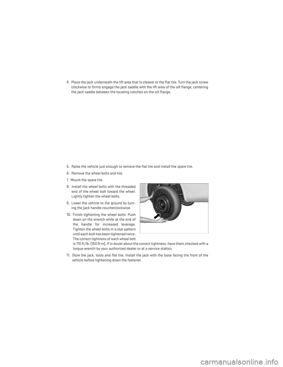
4. Place the jack underneath the lift area that is closest to the flat tire. Turn the jack screwclockwise to firmly engage the jack saddle with the lift area of the sill flange, centering
the jack saddle between the locating notches on the sill flange.
5. Raise the vehicle just enough to remove the flat tire and install the spare tire.
6. Remove the wheel bolts and tire.
7. Mount the spare tire.
8. Install the wheel bolts with the threaded end of the wheel bolt toward the wheel.
Lightly tighten the wheel bolts.
9. Lower the vehicle to the ground by turn- ing the jack handle counterclockwise.
10. Finish tightening the wheel bolts. Push down on the wrench while at the end of
the handle for increased leverage.
Tighten the wheel bolts in a star pattern
until each bolt has been tightened twice.
The correct tightness of each wheel bolt
is 110 ft/lb. (150 N·m). If in doubt about the correct tightness, have them checked with a
torque wrench by your authorized dealer or at a service station.
11. Stow the jack, tools and flat tire. Install the jack with the base facing the front of the vehicle before tightening down the fastener.
WHAT TO DO IN EMERGENCIES
88
Page 91 of 132
Road Tire Installation
Vehicles Equipped With Wheel Covers
1. Mount the road tire on the axle.
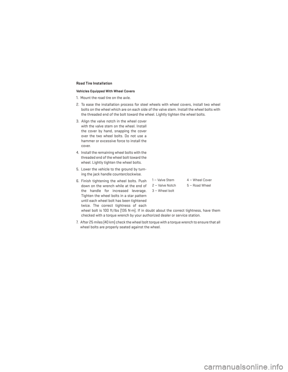
2. To ease the installation process for steel wheels with wheel covers, install two wheelbolts on the wheel which are on each side of the valve stem. Install the wheel bolts with
the threaded end of the bolt toward the wheel. Lightly tighten the wheel bolts.
3. Align the valve notch in the wheel cover with the valve stem on the wheel. Install
the cover by hand, snapping the cover
over the two wheel bolts. Do not use a
hammer or excessive force to install the
cover.
4. Install the remaining wheel bolts with the threaded end of the wheel bolt toward the
wheel. Lightly tighten the wheel bolts.
5. Lower the vehicle to the ground by turn- ing the jack handle counterclockwise.
6. Finish tightening the wheel bolts. Push down on the wrench while at the end of
the handle for increased leverage.
Tighten the wheel bolts in a star pattern
until each wheel bolt has been tightened
twice. The correct tightness of each
wheel bolt is 100 ft/lbs (135 N·m). If in doubt about the correct tightness, have them
checked with a torque wrench by your authorized dealer or service station.
7. After 25 miles (40 km) check the wheel bolt torque with a torque wrench to ensure that all wheel bolts are properly seated against the wheel.
1 — Valve Stem 4 — Wheel Cover
2 — Valve Notch 5 — Road Wheel
3 — Wheel bolt
WHAT TO DO IN EMERGENCIES
89
Page 92 of 132
Vehicles Without Wheel Covers
1. Mount the road tire on the axle.
2. Install the remaining wheel bolts with the threaded end of the wheel bolt toward thewheel. Lightly tighten the wheel bolts.
3. Lower the vehicle to the ground by turning the jack handle counterclockwise.
4. Finish tightening the wheel bolts. Push down on the wrench while at the end of the handle for increased leverage. Tighten the wheel bolts in a star pattern until each bolt has been
tightened twice. The correct tightness of each wheel bolt is 100 ft/lbs (135 N·m). If in
doubt about the correct tightness, have them checked with a torque wrench by your
authorized dealer or service station.
5. After 25 miles (40 km) check the wheel bolt torque with a torque wrench to ensure that all wheel bolts are properly seated against the wheel.
CAUTION!
• The winch mechanism is designed for use with the jack-handle only. Use of an air wrench or other power tools is not recommended and they can damage the winch.
• Do not attempt to raise the vehicle by jacking on locations other than those indicated
in the Jacking Instructions for this vehicle.
• Be sure to mount the spare tire with the valve stem facing outward. The vehicle could
be damaged if the spare tire is mounted incorrectly.
WHAT TO DO IN EMERGENCIES
90
Page 125 of 132
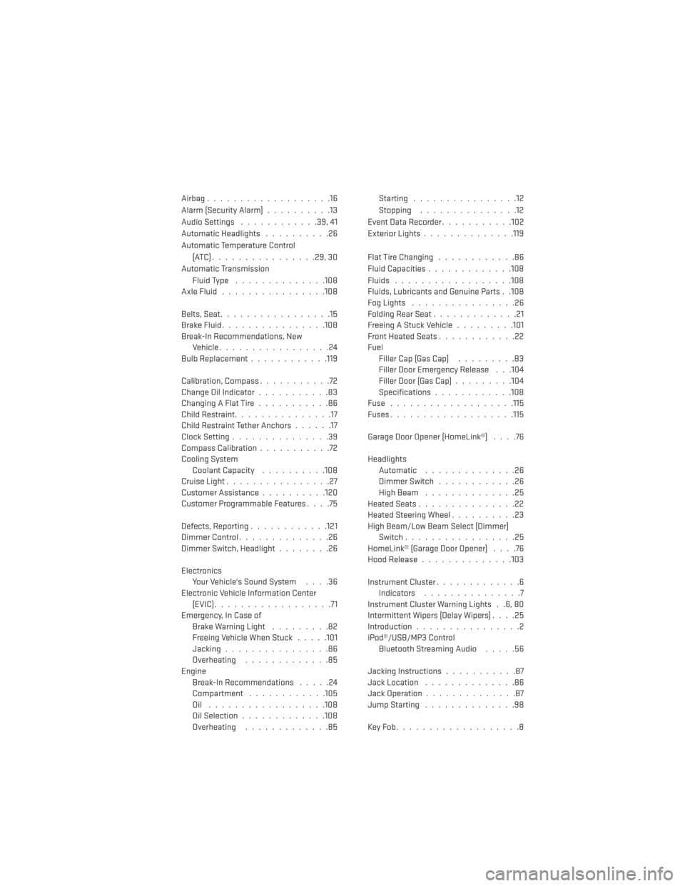
Airbag...................16
Alarm (Security Alarm)..........13
Audio Settings ............39,41
Automatic Headlights ..........26
Automatic Temperature Control (ATC)................29,30
Automatic Transmission Fluid Type ..............108
AxleFluid................108
Belts, Seat .................15
BrakeFluid................108
Break-In Recommendations, New Vehicle .................24
BulbReplacement........... .119
Calibration, Compass ...........72
Change Oil Indicator ...........83
Changing A Flat Tire ...........86
Child Restraint ...............17
Child Restraint Tether Anchors ......17
Clock Setting ...............39
Compass Calibration ...........72
Cooling System Coolant Capacity ..........108
Cruise Light ................27
Customer Assistance ..........120
Customer Programmable Features ....75
Defects, Reporting ............121
Dimmer Control ..............26
Dimmer Switch, Headlight ........26
Electronics Your Vehicle's Sound System ....36
Electronic Vehicle Information Center (EVIC)..................71
Emergency, In Case of Brake Warning Light .........82
Freeing Vehicle When Stuck .....101
Jacking ................86
Overheating .............85
Engine Break-In Recommendations .....24
Compartment ............105
Oil ..................108
Oil Selection .............108
Overheating .............85 Starting ................12
Stopping
...............12
EventDataRecorder...........102
Exterior Lights ..............119
FlatTireChanging ............86
Fluid Capacities .............108
Fluids ..................108
Fluids, Lubricants and Genuine Parts . .108
FogLights ................26
Folding Rear Seat .............21
Freeing A Stuck Vehicle .........101
Front Heated Seats ............22
Fuel Filler Cap (Gas Cap) .........83
Filler Door Emergency Release . . .104
Filler Door (Gas Cap) .........104
Specifications ............108
Fuse ...................115
Fuses.................. .115
Garage Door Opener (HomeLink®) ....76
Headlights Automatic ..............
26
Dimmer Switch ............26
HighBeam ..............25
Heated Seats ...............22
Heated Steering Wheel ..........23
High Beam/Low Beam Select (Dimmer) Switch .................25
HomeLink® (Garage Door Opener) ....76
Hood Release ..............103
Instrument Cluster .............6
Indicators ...............7
Instrument Cluster Warning Lights . .6, 80
Intermittent Wipers (Delay Wipers) ....25
Introduction ................2
iPod®/USB/MP3 Control Bluetooth Streaming Audio .....56
Jacking Instructions ...........87
Jack Location ..............86
Jack Operation ..............87
Jump Starting ..............98
KeyFob...................8
INDEX
123
Page 126 of 132
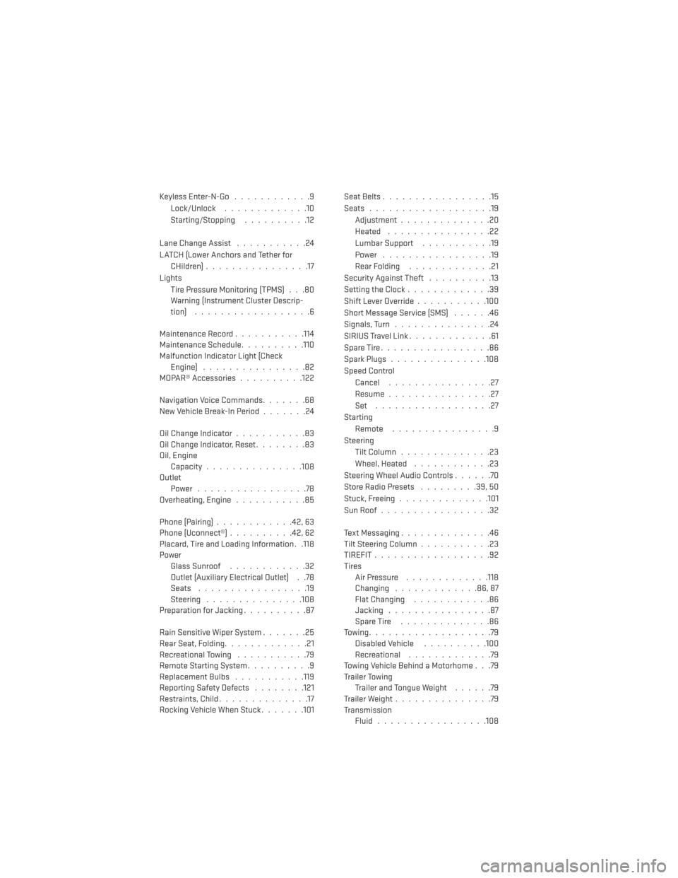
Keyless Enter-N-Go............9
Lock/Unlock .............10
Starting/Stopping ..........12
Lane Change Assist ...........24
LATCH (Lower Anchors and Tether for CHildren) ................17
Lights Tire Pressure Monitoring (TPMS) . . .80
Warning (Instrument Cluster Descrip-
tion) ..................6
Maintenance Record ...........114
Maintenance Schedule ..........110
Malfunction Indicator Light (Check Engine) ................82
MOPAR® Accessories ..........122
Navigation Voice Commands .......68
New Vehicle Break-In Period .......24
Oil Change Indicator ...........83
Oil Change Indicator, Reset ........83
Oil, Engine Capacity...............108
Outlet Power .................78
Overheating, Engine ...........85
Phone (Pairing) ............42,63
Phone (Uconnect®) ..........42,62
Placard, Tire and Loading Information . .118
Power Glass Sunroof ............32
Outlet (Auxiliary Electrical Outlet) . .78
Seats .................19
Steering ...............108
Preparation for Jacking ..........87
Rain Sensitive Wiper System .......25
Rear Seat, Folding .............21
Recreational Towing ...........79
Remote Starting System ..........9
ReplacementBulbs .......... .119
Reporting Safety Defects ........121
Restraints, Child ..............17
Rocking Vehicle When Stuck .......101Seat Belts
.................15
Seats ...................19
Adjustment..............20
Heated ................22
Lumbar Support ...........19
Power .................19
Rear Folding .............21
Security Against Theft ..........13
Setting the Clock .............39
Shift Lever Override ...........100
Short Message Service (SMS) ......46
Signals, Turn ...............24
SIRIUSTravelLink.............61
SpareTire.................86
SparkPlugs...............108
Speed Control Cancel ................27
Resume ................27
Set ..................27
Starting Remote ................9
Steering Tilt Column ..............23
Wheel, Heated ............23
Steering Wheel Audio Controls ......70
Store Radio Presets .........39,50
Stuck,
Freeing ..............101
SunRoof.................32
Text Messaging ..............46
Tilt Steering Column ...........23
TIREFIT..................92
Tires Air Pressure .............118
Changing .............86,87
Flat Changing ............86
Jacking ................87
SpareTire ..............86
Towing...................79 Disabled Vehicle ..........100
Recreational .............79
Towing Vehicle Behind a Motorhome . . .79
Trailer Towing Trailer and Tongue Weight ......79
Trailer Weight ...............79
Transmission Fluid .................108
INDEX
124