center console DODGE DART 2014 PF / 1.G Owners Manual
[x] Cancel search | Manufacturer: DODGE, Model Year: 2014, Model line: DART, Model: DODGE DART 2014 PF / 1.GPages: 656, PDF Size: 4.73 MB
Page 276 of 656
GARAGE DOOR OPENER — IF EQUIPPED
HomeLink® replaces up to three hand-held transmitters
that operate devices such as garage door openers, motor-
ized gates, lighting or home security systems. The
HomeLink® unit is powered by your vehicles 12 Volt
battery.
The HomeLink® buttons, located on either the overhead
console, headliner or sunvisor, designate the three differ-
ent HomeLink® channels. The HomeLink® indicator is
located above the center button.
HomeLink® Buttons/Overhead Consoles
274 UNDERSTANDING THE FEATURES OF YOUR VEHICLE
Page 290 of 656
CAUTION!
•Do not exceed the maximum power of 160 Watts
(13 Amps) at 12 Volts. If the 160 Watt (13 Amp)
power rating is exceeded the fuse protecting the
system will need to be replaced.
• Power outlets are designed for accessory plugs
only. Do not insert any other object in the power
outlets as this will damage the outlet and blow the
fuse. Improper use of the power outlet can cause
damage not covered by your New Vehicle Limited
Warranty.
There is also a 12 Volt power outlet located in the center
console. This power outlet has power available only
when the ignition is placed in the ACC or RUN position.
Center Console Outlet
288 UNDERSTANDING THE FEATURES OF YOUR VEHICLE
Page 291 of 656
WARNING!
To avoid serious injury or death:
•Only devices designed for use in this type of outlet
should be inserted into any 12 Volt outlet.
• Do not touch with wet hands.
• Close the lid when not in use and while driving the
vehicle.
• If this outlet is mishandled, it may cause an electric
shock and failure.
CAUTION!
•Many accessories that can be plugged in draw power
from the vehicle’s battery, even when not in use (i.e.,
cellular phones, etc.). Eventually, if plugged in long
enough, the vehicle’s battery will discharge suffi-
ciently to degrade battery life and/or prevent the
engine from starting.
(Continued)
Underhood Fuses (Power Outlet Fuses)
1 — F84 Fuse 20 A Yellow Cigar Lighter
2 — F30 Fuse 20 A Yellow Center Console Outlet
3
UNDERSTANDING THE FEATURES OF YOUR VEHICLE 289
Page 292 of 656
CAUTION!(Continued)
•Accessories that draw higher power (i.e., coolers,
vacuum cleaners, lights, etc.), will degrade the
battery even more quickly. Only use these intermit-
tently and with greater caution.
• After the use of high power draw accessories, or
long periods of the vehicle not being started (with
accessories still plugged in), the vehicle must be
driven a sufficient length of time to allow the
alternator to recharge the vehicle’s battery.
• Power outlets are designed for accessory plugs
only. Do not hang any type of accessory or acces-
sory bracket from the plug. Improper use of the
power outlet can cause damage.
CUPHOLDERS
Front Seat Cupholders
The cupholders are located in the center console forward
of the armrest between the front seats.
Front Cupholders
290 UNDERSTANDING THE FEATURES OF YOUR VEHICLE
Page 294 of 656
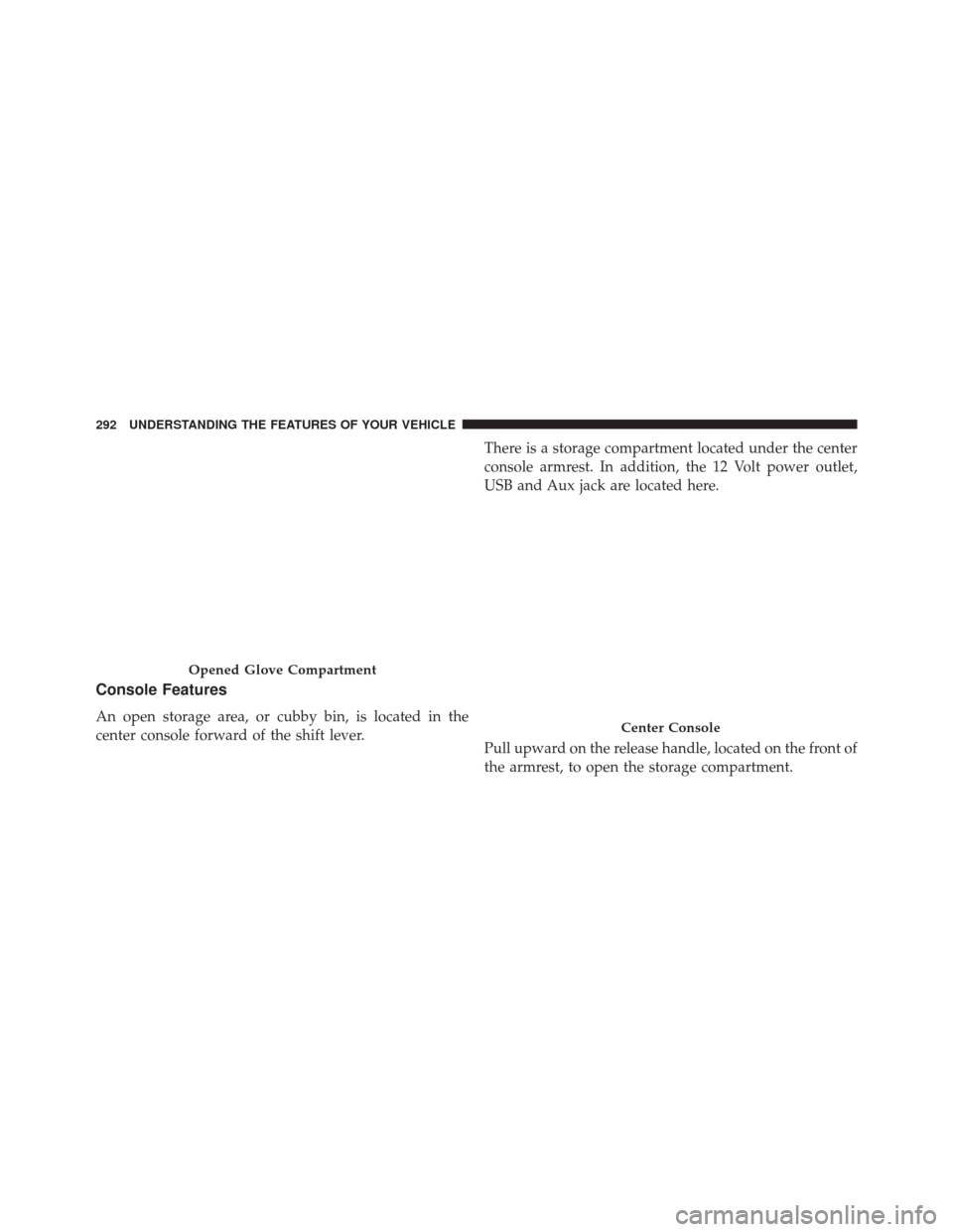
Console Features
An open storage area, or cubby bin, is located in the
center console forward of the shift lever.There is a storage compartment located under the center
console armrest. In addition, the 12 Volt power outlet,
USB and Aux jack are located here.
Pull upward on the release handle, located on the front of
the armrest, to open the storage compartment.
Opened Glove Compartment
Center Console
292 UNDERSTANDING THE FEATURES OF YOUR VEHICLE
Page 381 of 656
Security
If this radio is installed in a vehicle that does not have a
matching Vehicle Identification Number (VIN) an Secu-
rity code will need to be entered by the dealer.
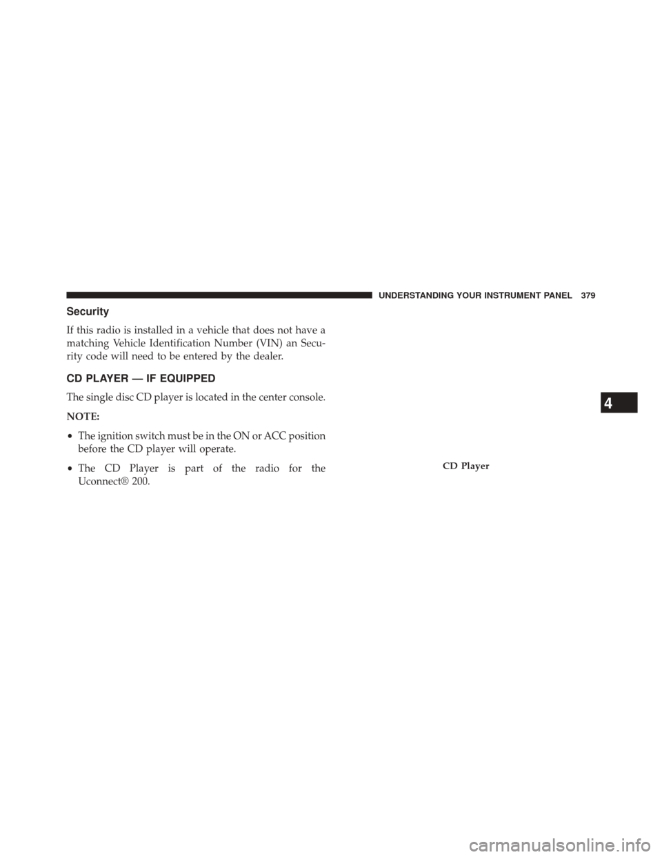
CD PLAYER — IF EQUIPPED
The single disc CD player is located in the center console.
NOTE:
•The ignition switch must be in the ON or ACC position
before the CD player will operate.
• The CD Player is part of the radio for the
Uconnect® 200.
CD Player
4
UNDERSTANDING YOUR INSTRUMENT PANEL 379
Page 383 of 656
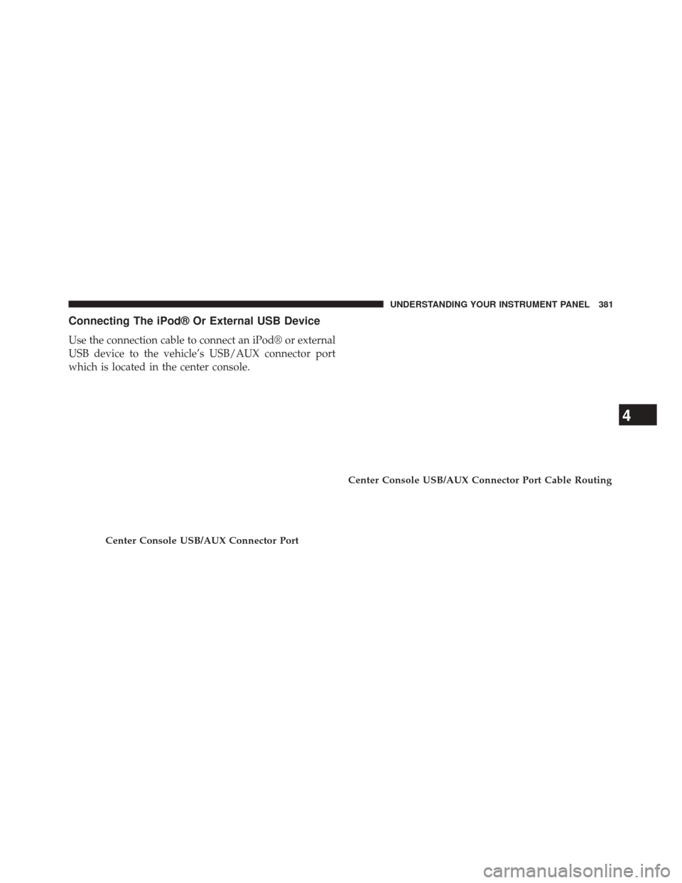
Connecting The iPod® Or External USB Device
Use the connection cable to connect an iPod® or external
USB device to the vehicle’s USB/AUX connector port
which is located in the center console.
Center Console USB/AUX Connector Port
Center Console USB/AUX Connector Port Cable Routing
4
UNDERSTANDING YOUR INSTRUMENT PANEL 381
Page 384 of 656
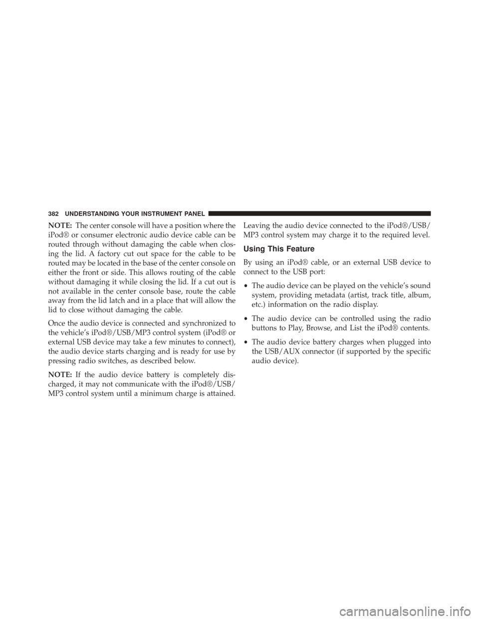
NOTE:The center console will have a position where the
iPod® or consumer electronic audio device cable can be
routed through without damaging the cable when clos-
ing the lid. A factory cut out space for the cable to be
routed may be located in the base of the center console on
either the front or side. This allows routing of the cable
without damaging it while closing the lid. If a cut out is
not available in the center console base, route the cable
away from the lid latch and in a place that will allow the
lid to close without damaging the cable.
Once the audio device is connected and synchronized to
the vehicle’s iPod®/USB/MP3 control system (iPod® or
external USB device may take a few minutes to connect),
the audio device starts charging and is ready for use by
pressing radio switches, as described below.
NOTE: If the audio device battery is completely dis-
charged, it may not communicate with the iPod®/USB/
MP3 control system until a minimum charge is attained. Leaving the audio device connected to the iPod®/USB/
MP3 control system may charge it to the required level.
Using This Feature
By using an iPod® cable, or an external USB device to
connect to the USB port:
•
The audio device can be played on the vehicle’s sound
system, providing metadata (artist, track title, album,
etc.) information on the radio display.
• The audio device can be controlled using the radio
buttons to Play, Browse, and List the iPod® contents.
• The audio device battery charges when plugged into
the USB/AUX connector (if supported by the specific
audio device).
382 UNDERSTANDING YOUR INSTRUMENT PANEL
Page 445 of 656
The parking brake lever is located in the center console.
To apply the parking brake, pull the lever up as firmly as
possible. To release the parking brake, pull the lever up
slightly, press the center button, then lower the lever
completely.
When the parking brake is applied with the ignition
switch in the ON position, the “Brake Warning Light” in
the instrument cluster will illuminate.
NOTE:
•When the parking brake is applied and the automatic
transmission is placed in gear, the “Brake Warning
Light” will flash. If vehicle speed is detected, a chime
will sound to alert the driver. Fully release the parking
brake before attempting to move the vehicle. •
This light only shows that the parking brake is ap-
plied. It does not show the degree of brake application.
When parking on a hill, it is important to turn the front
wheels toward the curb on a downhill grade and away
from the curb on an uphill grade. For vehicles
equipped with an automatic transmission, apply the
parking brake before placing the shift lever in PARK,
otherwise the load on the transmission locking mecha-
nism may make it difficult to move the shift lever out
of PARK. The parking brake should always be applied
whenever the driver is not in the vehicle.
WARNING!
•Never use the PARK position as a substitute for the
parking brake. Always apply the parking brake
fully when parked to guard against vehicle move-
ment and possible injury or damage.
(Continued)
5
STARTING AND OPERATING 443
Page 551 of 656
WARNING!
Fast spinning tires can be dangerous. Forces gener-
ated by excessive wheel speeds may cause damage, or
even failure, of the axle and tires. A tire could
explode and injure someone. Do not spin your vehi-
cle’s wheels faster than 30 mph (48 km/h) or for
longer than 30 seconds continuously without stop-
ping when you are stuck and do not let anyone near
a spinning wheel, no matter what the speed.
SHIFT LEVER OVERRIDE
If a malfunction occurs and the shift lever cannot be
moved out of the PARK position, you can use the
following procedure to temporarily move the shift lever:
1. Turn the engine OFF.
2. Firmly apply the parking brake.3. Remove the rubber storage tray liner from the center
console, then lift up the front of the shift lever bezel,
carefully disengage the bezel from the shift lever
housing, and slide it up to the top of the shift lever.
4. Press and maintain firm pressure on the brake pedal.
Shift Lever Bezel
6
WHAT TO DO IN EMERGENCIES 549