park assist DODGE DART 2014 PF / 1.G User Guide
[x] Cancel search | Manufacturer: DODGE, Model Year: 2014, Model line: DART, Model: DODGE DART 2014 PF / 1.GPages: 140, PDF Size: 4.57 MB
Page 38 of 140

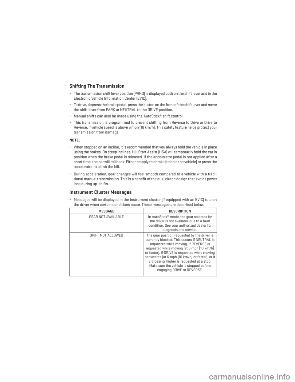
Shifting The Transmission
• The transmission shift lever position (PRND) is displayed both on the shift lever and in theElectronic Vehicle Information Center (EVIC).
• To drive, depress the brake pedal, press the button on the front of the shift lever and move the shift lever from PARK or NEUTRAL to the DRIVE position.
• Manual shifts can also be made using the AutoStick® shift control.
• This transmission is programmed to prevent shifting from Reverse to Drive or Drive to Reverse, if vehicle speed is above 6 mph (10 km/h). This safety feature helps protect your
transmission from damage.
NOTE:
• When stopped on an incline, it is recommended that you always hold the vehicle in place using the brakes. On steep inclines, Hill Start Assist (HSA) will temporarily hold the car in
position when the brake pedal is released. If the accelerator pedal is not applied after a
short time, the car will roll back. Either reapply the brake (to hold the vehicle) or press the
accelerator to climb the hill.
• During acceleration, gear changes will feel smooth compared to a vehicle with a tradi- tional manual transmission. This is a benefit of the dual clutch design that avoids power
loss during up-shifts.
Instrument Cluster Messages
• Messages will be displayed in the instrument cluster (if equipped with an EVIC) to alertthe driver when certain conditions occur. These messages are described below.
MESSAGE DESCRIPTION
GEAR NOT AVAILABLE In AutoStick® mode, the gear selected by
the driver is not available due to a fault
condition. See your authorized dealer for diagnosis and service.
SHIFT NOT ALLOWED The gear position requested by the driver is
currently blocked. This occurs if NEUTRAL is requested while moving, if REVERSE is
requested while moving (at 6 mph [10 km/h]
or faster), if DRIVE is requested while moving
backwards (at 6 mph [10 km/h] or faster), or if 3rd gear or higher is requested at a stop.Make sure the vehicle is stopped before engaging DRIVE or REVERSE.
OPERATING YOUR VEHICLE
36
Page 61 of 140

Main Navigation Menu
Acquiring Satellites
• The GPS Satellite strength bars indicate the strength of your satellite reception.
• Acquiring satellite signals can take a few minutes. When at least one of the bars is green,your device has acquired satellite signals. If no signal is found the Navigation system still
can operate with internal gyro direction & location based on data provided by the vehicle.
• Sensor Assisted GPS technology uses the speed sensors attached to your vehicle’s drivetrain and a gyroscope to supplement the existing GPS data. The combined data
provides accurate positioning for your vehicle in tunnels, indoor parking garages, urban
canyons, and any other area where GPS signals can become obstructed.
Finding Points Of Interest
• From the main Navigation menu touch the “Where To?” soft-key, then touch
“Points of Interest.”
• Select a Category and then a subcat- egory, if necessary.
• Select your destination and touch “Go.”
ELECTRONICS
59
Page 81 of 140

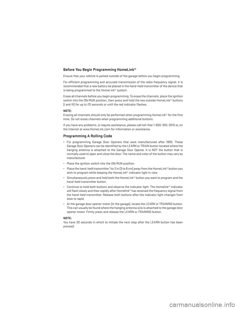
Before You Begin Programming HomeLink®
Ensure that your vehicle is parked outside of the garage before you begin programming.
For efficient programming and accurate transmission of the radio-frequency signal, it is
recommended that a new battery be placed in the hand-held transmitter of the device that
is being programmed to the HomeLink® system.
Erase all channels before you begin programming. To erase the channels, place the ignition
switch into the ON/RUN position, then press and hold the two outside HomeLink® buttons
(I and III) for up to 20 seconds or until the red indicator flashes.
NOTE:
Erasing all channels should only be performed when programming HomeLink® for the first
time. Do not erase channels when programming additional buttons.
If you have any problems, or require assistance, please call toll-free 1-800-355-3515 or, on
the Internet at www.HomeLink.com for information or assistance.
Programming A Rolling Code
• For programming Garage Door Openers that were manufactured after 1995. TheseGarage Door Openers can be identified by the LEARN or TRAIN button located where the
hanging antenna is attached to the Garage Door Opener. It is NOT the button that is
normally used to open and close the door. The name and color of the button may vary by
manufacturer.
• Place the ignition switch into the ON/RUN position.
• Place the hand-held transmitter 1 to 3 in (3 to 8 cm) away from the HomeLink® button you wish to program while keeping the HomeLink® indicator light in view.
• Simultaneously press and hold both the HomeLink® button you want to program and the hand-held transmitter button.
• Continue to hold both buttons and observe the indicator light. The Homelink® indicator will flash slowly and then rapidly after Homelink® has received the frequency signal from
the hand-held transmitter. Release both buttons after the indicator light changes from
slow to rapid.
• At the garage door opener motor (in the garage), locate the LEARN or TRAINING button. This can usually be found where the hanging antenna wire is attached to the garage door
opener motor. Firmly press and release the LEARN or TRAINING button.
NOTE:
You have 30 seconds in which to initiate the next step after the LEARN button has been
pressed.
ELECTRONICS
79
Page 99 of 140

(C) Injecting TIREFIT Sealant Into The Deflated Tire:
Always start the engine before turning ON the TIREFIT kit.
NOTE:
Manual transmission vehicles must have the parking brake engaged and the shift lever in
NEUTRAL.
After pressing the Power Button (4), the sealant (white fluid) will flow from the Sealant Bottle
(1) through the Sealant Hose (6) and into the tire.
NOTE:
Sealant may leak out through the puncture in the tire.
If the sealant (white fluid) does not flow within0–10seconds through the Sealant
Hose (6):
1. Press the Power Button (4) to turn Off the TIREFIT kit. Disconnect the Sealant Hose (6) from the valve stem. Make sure the valve stem is free of debris. Reconnect the Sealant
Hose (6) to the valve stem. Check that the Mode Select Knob (5) is in the Sealant Mode
position and not Air Mode. Press the Power Button (4) to turn On the TIREFIT kit.
2. Connect the Power Plug (8) to a different 12 Volt power outlet in your vehicle or another vehicle, if available. Make sure the engine is running before turning ON the TIREFIT kit.
3. The Sealant Bottle (1) may be empty due to previous use. Call for assistance.
NOTE:
If the Mode Select Knob (5) is on Air Mode and the pump is operating, air will dispense from
the Air Pump Hose (7) only, not the Sealant Hose (6).
If the sealant (white fluid) does flow through the Sealant Hose (6):
1. Continue to operate the pump until sealant is no longer flowing through the hose (typically takes 30 - 70 seconds). As the sealant flows through the Sealant Hose (6), the
Pressure Gauge (3) can read as high as 70 psi (4.8 Bar). The Pressure Gauge (3) will
decrease quickly from approximately 70 psi (4.8 Bar) to the actual tire pressure when the
Sealant Bottle (1) is empty.
2. The pump will start to inject air into the tire immediately after the Sealant Bottle (1) is empty. Continue to operate the pump and inflate the tire to the pressure indicated on the
tire pressure label on the driver-side latch pillar (recommended pressure). Check the tire
pressure by looking at the Pressure Gauge (3).
If the tire does not inflate to at least 26 psi (1.8 Bar) pressure within 15 minutes:
The tire is too badly damaged. Do not attempt to drive the vehicle further. Call for assistance.
NOTE:
If the tire becomes over-inflated, press the Deflation Button to reduce the tire pressure to
the recommended inflation pressure before continuing.
WHAT TO DO IN EMERGENCIES
97
Page 119 of 140

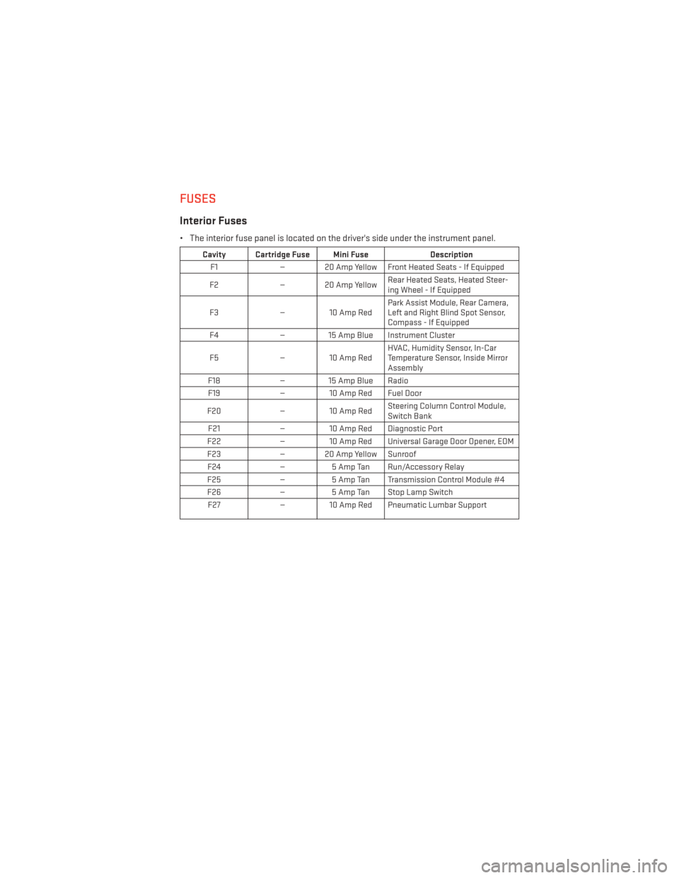
FUSES
Interior Fuses
• The interior fuse panel is located on the driver's side under the instrument panel.
Cavity Cartridge Fuse Mini FuseDescription
F1 — 20 Amp Yellow Front Heated Seats - If Equipped
F2 — 20 Amp Yellow Rear Heated Seats, Heated Steer-
ing Wheel - If Equipped
F3 — 10 Amp Red Park Assist Module, Rear Camera,
Left and Right Blind Spot Sensor,
Compass - If Equipped
F4 — 15 Amp Blue Instrument Cluster
F5 — 10 Amp Red HVAC, Humidity Sensor, In-Car
Temperature Sensor, Inside Mirror
Assembly
F18 — 15 Amp Blue Radio
F19 — 10 Amp Red Fuel Door
F20 — 10 Amp Red Steering Column Control Module,
Switch Bank
F21 — 10 Amp Red Diagnostic Port
F22 — 10 Amp Red Universal Garage Door Opener, EOM
F23 — 20 Amp Yellow Sunroof
F24 —5 Amp Tan Run/Accessory Relay
F25 —5 Amp Tan Transmission Control Module #4
F26 —5 Amp Tan Stop Lamp Switch
F27 — 10 Amp Red Pneumatic Lumbar Support
MAINTAINING YOUR VEHICLE
117