tow DODGE DART 2014 PF / 1.G User Guide
[x] Cancel search | Manufacturer: DODGE, Model Year: 2014, Model line: DART, Model: DODGE DART 2014 PF / 1.GPages: 140, PDF Size: 4.57 MB
Page 3 of 140
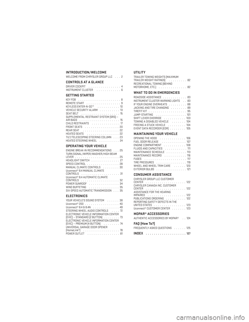
INTRODUCTION/WELCOME
WELCOME FROM CHRYSLER GROUP LLC . . . 2
CONTROLS AT A GLANCE
DRIVER COCKPIT................4
INSTRUMENT CLUSTER ............6
GETTING STARTED
KEYFOB .....................8
REMOTE START.................9
KEYLESS ENTER-N-GO™ ...........10
VEHICLE SECURITY ALARM ..........13
SEATBELT ...................15
SUPPLEMENTAL RESTRAINT SYSTEM (SRS) —
AIRBAGS ....................15
CHILD RESTRAINTS ..............17
FRONT SEATS .................20
REARSEAT ..................22
HEATEDSEATS ................22
TILT/TELESCOPING STEERING COLUMN . . . 23
HEATED STEERING WHEEL ..........24
OPERATING YOUR VEHICLE
ENGINE BREAK-IN RECOMMENDATIONS . . . 25
TURN SIGNAL/WIPER/WASHER/HIGH BEAM
LEVER......................25
HEADLIGHT SWITCH ..............27
SPEED CONTROL ................28
MANUAL CLIMATE CONTROLS ........30
Uconnect® 8.4 MANUAL CLIMATE
CONTROLS ...................31
Uconnect® 8.4 AUTOMATIC CLIMATE
CONTROLS ...................32
POWER SUNROOF ...............34
WIND BUFFETING ...............35
SIX-SPEED AUTOMATIC TRANSMISSION . . . 35
ELECTRONICS
YOUR VEHICLE'S SOUND SYSTEM ......38
Uconnect® 200 .................40
Uconnect® 8.4 & 8.4N .............49
STEERING WHEEL AUDIO CONTROLS ....72
ELECTRONIC VEHICLE INFORMATION CENTER
(EVIC) — STANDARD (2 BUTTON) ........73
ELECTRONIC VEHICLE INFORMATION CENTER
(EVIC) — PREMIUM (4 BUTTON) ........74
UNIVERSAL GARAGE DOOR OPENER
(HomeLink®) ..................78
POWER OUTLET ................81
UTILITY
TRAILER TOWING WEIGHTS (MAXIMUM
TRAILERWEIGHTRATINGS) .........82
RECREATIONAL TOWING (BEHIND
MOTORHOME, ETC.) ..............82
WHAT TO DO IN EMERGENCIES
ROADSIDE ASSISTANCE ............83INSTRUMENT CLUSTER WARNING LIGHTS..83
IF YOUR ENGINE OVERHEATS .........88
JACKING AND TIRE CHANGING ........89
TIREFIT KIT ...................95
JUMP-STARTING ...............101
SHIFT LEVER OVERRIDE ...........103
TOWING A DISABLED VEHICLE .......104
FREEING A STUCK VEHICLE .........104
EVENT DATA RECORDER (EDR) ........105
MAINTAINING YOUR VEHICLE
OPENING THE HOOD.............106
FUEL DOOR RELEASE ............107
ENGINE COMPARTMENT ...........108
FLUIDS AND CAPACITIES ...........111
MAINTENANCE SCHEDULE ..........113
MAINTENANCE RECORD ...........116
FUSES .....................117
TIRE PRESSURES ...............119
WHEEL AND WHEEL TRIM CARE ......120
EXTERIOR BULBS ...............121
CONSUMER ASSISTANCE
CHRYSLER GROUP LLC CUSTOMER
CENTER....................122
CHRYSLER CANADA INC. CUSTOMER
CENTER ....................122
ASSISTANCE FOR THE HEARING
IMPAIRED ...................122
PUBLICATIONS ORDERING ..........122
REPORTING SAFETY DEFECTS IN THE
UNITEDSTATES ................123
Uconnect® CUSTOMER CENTER .......123
MOPAR® ACCESSORIES
AUTHENTIC ACCESSORIES BY MOPAR® . . 124
FAQ (How To?)
FREQUENTLY ASKED QUESTIONS ......125
INDEX....................127
TABLE OF CONTENTS
Page 28 of 140
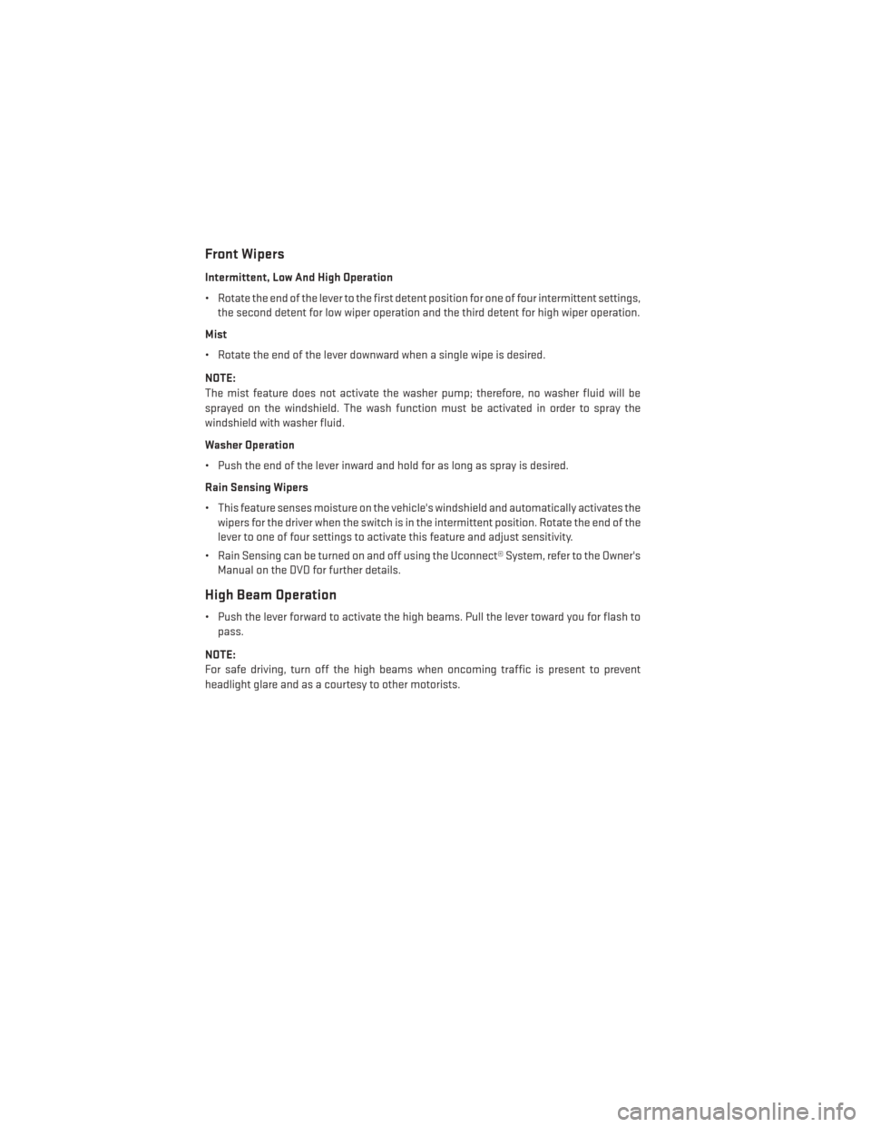
Front Wipers
Intermittent, Low And High Operation
• Rotate the end of the lever to the first detent position for one of four intermittent settings,the second detent for low wiper operation and the third detent for high wiper operation.
Mist
• Rotate the end of the lever downward when a single wipe is desired.
NOTE:
The mist feature does not activate the washer pump; therefore, no washer fluid will be
sprayed on the windshield. The wash function must be activated in order to spray the
windshield with washer fluid.
Washer Operation
• Push the end of the lever inward and hold for as long as spray is desired.
Rain Sensing Wipers
• This feature senses moisture on the vehicle's windshield and automatically activates the wipers for the driver when the switch is in the intermittent position. Rotate the end of the
lever to one of four settings to activate this feature and adjust sensitivity.
• Rain Sensing can be turned on and off using the Uconnect® System, refer to the Owner's Manual on the DVD for further details.
High Beam Operation
• Push the lever forward to activate the high beams. Pull the lever toward you for flash topass.
NOTE:
For safe driving, turn off the high beams when oncoming traffic is present to prevent
headlight glare and as a courtesy to other motorists.
OPERATING YOUR VEHICLE
26
Page 69 of 140
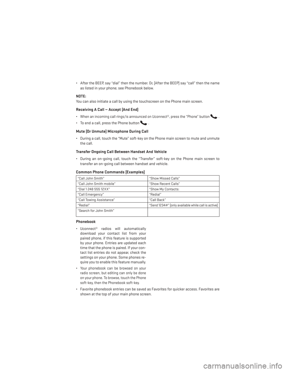
• After the BEEP, say “dial” then the number. Or, (After the BEEP) say “call” then the nameas listed in your phone; see Phonebook below.
NOTE:
You can also initiate a call by using the touchscreen on the Phone main screen.
Receiving A Call — Accept (And End)
•When an incoming call rings/is announced on Uconnect®, press the “Phone” button.
• To end a call, press the Phone button.
Mute (Or Unmute) Microphone During Call
• During a call, touch the “Mute” soft-key on the Phone main screen to mute and unmute the call.
Transfer Ongoing Call Between Handset And Vehicle
• During an on-going call, touch the “Transfer” soft-key on the Phone main screen totransfer an on-going call between handset and vehicle.
Common Phone Commands (Examples)
“Call John Smith” “Show Missed Calls”
“Call John Smith mobile” “Show Recent Calls”
“Dial 1 248 555 12XX” “Show My Contacts:
“Call Emergency” “Redial”
“Call Towing Assistance” “Call Back”
“Redial”
“Send 1234#” (only available while call is active)
“Search for John Smith”
Phonebook
• Uconnect® radios will automatically download your contact list from your
paired phone, if this feature is supported
by your phone. Entries are updated each
time that the phone is paired. If your con-
tact list entries do not appear, check the
settings on your phone. Some phones re-
quire you to enable this feature manually.
•
Your phonebook can be browsed on your
radio screen, but editing can only be done
on your phone. To browse, touch the Phone
soft-key, then the Phonebook soft-key.
• Favorite phonebook entries can be saved as Favorites for quicker access. Favorites are
shown at the top of your main phone screen.
ELECTRONICS
67
Page 73 of 140
NOTE:
For the shortened Sirius XM Satellite Radio mode commands to be recognized you must be
in that mode. For example, if you are in Sirius XM Satellite Radio mode you can say “39”, but
if you are not in Sirius XM mode, you would need to say “Tune to Satellite Channel 39.”
Common Navigation Voice Commands
• To access the navigation voice commands, press the Uconnect® Voice Command
button while in any mode and say “Navigation.”
• Once in the Navigation feature, you can simply Say What You Seeon the touchscreen to
give a navigation voice command.
• Locating an address can be given as a one shot entry. For example, after saying “Find
Address” and the system is ready, you can say the entire address in one command,
“1234 1st Street, Any Town, Michigan.” If you are searching for a particular address or
Point Of Interest, the available voice commands depend on what is displayed on the
touchscreen.
• When the Voice Command system is ready to be given a command, the green indicator is visible in the right corner of the touchscreen.
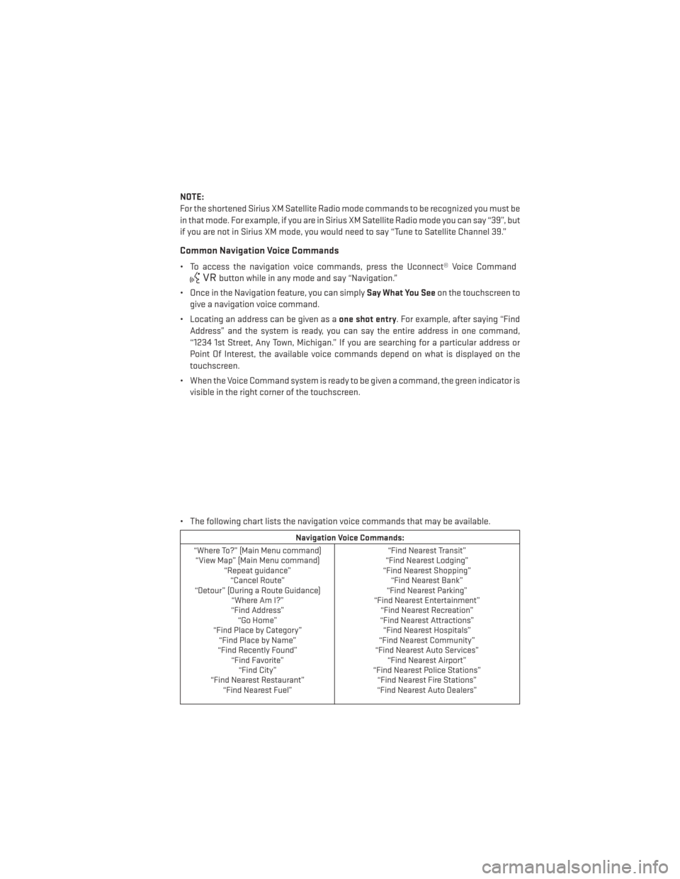
• The following chart lists the navigation voice commands that may be available.
Navigation Voice Commands:
“Where To?” (Main Menu command) “View Map” (Main Menu command) “Repeat guidance”“Cancel Route”
“Detour” (During a Route Guidance) “Where Am I?”
“Find Address” “Go Home”
“Find Place by Category” “Find Place by Name”
“Find Recently Found” “Find Favorite”“Find City”
“Find Nearest Restaurant” “Find Nearest Fuel” “Find Nearest Transit”
“Find Nearest Lodging”
“Find Nearest Shopping” “Find Nearest Bank”
“Find Nearest Parking”
“Find Nearest Entertainment” “Find Nearest Recreation”
“Find Nearest Attractions” “Find Nearest Hospitals”
“Find Nearest Community”
“Find Nearest Auto Services” “Find Nearest Airport”
“Find Nearest Police Stations” “Find Nearest Fire Stations”
“Find Nearest Auto Dealers”
ELECTRONICS
71
Page 84 of 140
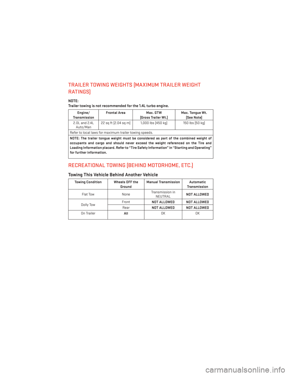
TRAILER TOWING WEIGHTS (MAXIMUM TRAILER WEIGHT
RATINGS)
NOTE:
Trailer towing is not recommended for the 1.4L turbo engine.
Engine/
Transmission Frontal Area
Max. GTW
(Gross Trailer Wt.) Max. Tongue Wt.
(See Note)
2.0L and 2.4L Auto/Man 22 sq ft (2.04 sq m) 1,000 lbs (450 kg) 150 lbs (50 kg)
Refer to local laws for maximum trailer towing speeds.
NOTE: The trailer tongue weight must be considered as part of the combined weight of
occupants and cargo and should never exceed the weight referenced on the Tire and
Loading Information placard. Refer to “Tire Safety Information” in “Starting and Operating”
for further information.
RECREATIONAL TOWING (BEHIND MOTORHOME, ETC.)
Towing This Vehicle Behind Another Vehicle
Towing Condition Wheels OFF the GroundManual Transmission Automatic
Transmission
Flat Tow NoneTransmission in
NEUTRAL NOT ALLOWED
Dolly Tow Front
NOT ALLOWED NOT ALLOWED
Rear NOT ALLOWED NOT ALLOWED
On Trailer AllOK
OK
UTILITY
82
Page 87 of 140
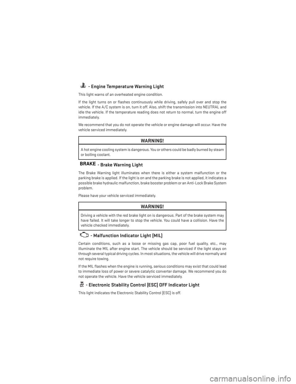
- Engine Temperature Warning Light
This light warns of an overheated engine condition.
If the light turns on or flashes continuously while driving, safely pull over and stop the
vehicle. If the A/C system is on, turn it off. Also, shift the transmission into NEUTRAL and
idle the vehicle. If the temperature reading does not return to normal, turn the engine off
immediately.
We recommend that you do not operate the vehicle or engine damage will occur. Have the
vehicle serviced immediately.
WARNING!
A hot engine cooling system is dangerous. You or others could be badly burned by steam
or boiling coolant.
BRAKE- Brake Warning Light
The Brake Warning light illuminates when there is either a system malfunction or the
parking brake is applied. If the light is on and the parking brake is not applied, it indicates a
possible brake hydraulic malfunction, brake booster problem or an Anti-Lock Brake System
problem.
Please have your vehicle serviced immediately.
WARNING!
Driving a vehicle with the red brake light on is dangerous. Part of the brake system may
have failed. It will take longer to stop the vehicle. You could have a collision. Have the
vehicle checked immediately.
- Malfunction Indicator Light (MIL)
Certain conditions, such as a loose or missing gas cap, poor fuel quality, etc., may
illuminate the MIL after engine start. The vehicle should be serviced if the light stays on
through several typical driving cycles. In most situations, the vehicle will drive normally and
not require towing.
If the MIL flashes when the engine is running, serious conditions may exist that could lead
to immediate loss of power or severe catalytic converter damage. We recommend you do
not operate the vehicle. Have the vehicle serviced immediately.
- Electronic Stability Control (ESC) OFF Indicator Light
This light indicates the Electronic Stability Control (ESC) is off.
WHAT TO DO IN EMERGENCIES
85
Page 88 of 140
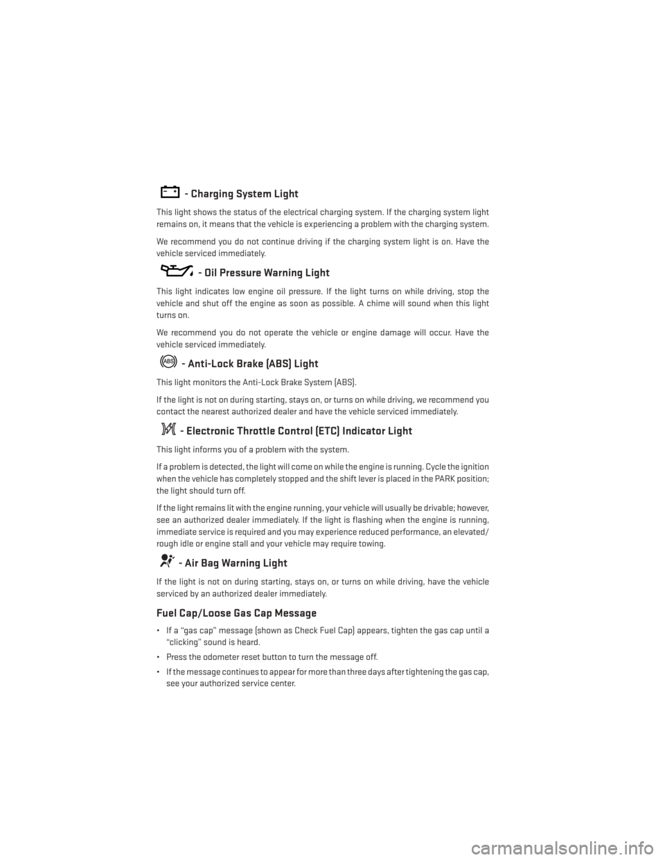
- Charging System Light
This light shows the status of the electrical charging system. If the charging system light
remains on, it means that the vehicle is experiencing a problem with the charging system.
We recommend you do not continue driving if the charging system light is on. Have the
vehicle serviced immediately.
- Oil Pressure Warning Light
This light indicates low engine oil pressure. If the light turns on while driving, stop the
vehicle and shut off the engine as soon as possible. A chime will sound when this light
turns on.
We recommend you do not operate the vehicle or engine damage will occur. Have the
vehicle serviced immediately.
- Anti-Lock Brake (ABS) Light
This light monitors the Anti-Lock Brake System (ABS).
If the light is not on during starting, stays on, or turns on while driving, we recommend you
contact the nearest authorized dealer and have the vehicle serviced immediately.
- Electronic Throttle Control (ETC) Indicator Light
This light informs you of a problem with the system.
If a problem is detected, the light will come on while the engine is running. Cycle the ignition
when the vehicle has completely stopped and the shift lever is placed in the PARK position;
the light should turn off.
If the light remains lit with the engine running, your vehicle will usually be drivable; however,
see an authorized dealer immediately. If the light is flashing when the engine is running,
immediate service is required and you may experience reduced performance, an elevated/
rough idle or engine stall and your vehicle may require towing.
- Air Bag Warning Light
If the light is not on during starting, stays on, or turns on while driving, have the vehicle
serviced by an authorized dealer immediately.
Fuel Cap/Loose Gas Cap Message
• If a “gas cap” message (shown as Check Fuel Cap) appears, tighten the gas cap until a“clicking” sound is heard.
• Press the odometer reset button to turn the message off.
• If the message continues to appear for more than three days after tightening the gas cap, see your authorized service center.
WHAT TO DO IN EMERGENCIES
86
Page 91 of 140
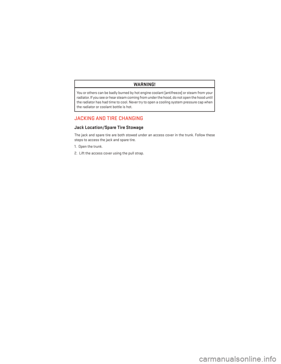
WARNING!
You or others can be badly burned by hot engine coolant (antifreeze) or steam from your
radiator. If you see or hear steam coming from under the hood, do not open the hood until
the radiator has had time to cool. Never try to open a cooling system pressure cap when
the radiator or coolant bottle is hot.
JACKING AND TIRE CHANGING
Jack Location/Spare Tire Stowage
The jack and spare tire are both stowed under an access cover in the trunk. Follow these
steps to access the jack and spare tire.
1. Open the trunk.
2. Lift the access cover using the pull strap.
WHAT TO DO IN EMERGENCIES
89
Page 94 of 140
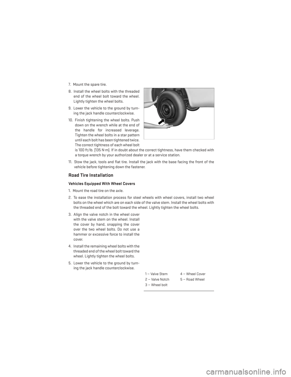
7. Mount the spare tire.
8. Install the wheel bolts with the threadedend of the wheel bolt toward the wheel.
Lightly tighten the wheel bolts.
9. Lower the vehicle to the ground by turn- ing the jack handle counterclockwise.
10. Finish tightening the wheel bolts. Push down on the wrench while at the end of
the handle for increased leverage.
Tighten the wheel bolts in a star pattern
until each bolt has been tightened twice.
The correct tightness of each wheel bolt
is 100 ft/lb. (135 N·m). If in doubt about the correct tightness, have them checked with
a torque wrench by your authorized dealer or at a service station.
11. Stow the jack, tools and flat tire. Install the jack with the base facing the front of the vehicle before tightening down the fastener.
Road Tire Installation
Vehicles Equipped With Wheel Covers
1. Mount the road tire on the axle.
2. To ease the installation process for steel wheels with wheel covers, install two wheelbolts on the wheel which are on each side of the valve stem. Install the wheel bolts with
the threaded end of the bolt toward the wheel. Lightly tighten the wheel bolts.
3. Align the valve notch in the wheel cover with the valve stem on the wheel. Install
the cover by hand, snapping the cover
over the two wheel bolts. Do not use a
hammer or excessive force to install the
cover.
4. Install the remaining wheel bolts with the threaded end of the wheel bolt toward the
wheel. Lightly tighten the wheel bolts.
5. Lower the vehicle to the ground by turn- ing the jack handle counterclockwise.
1 — Valve Stem 4 — Wheel Cover
2 — Valve Notch 5 — Road Wheel
3 — Wheel bolt
WHAT TO DO IN EMERGENCIES
92
Page 95 of 140
6. Finish tightening the wheel bolts. Push down on the wrench while at the end of thehandle for increased leverage. Tighten the wheel bolts in a star pattern until each wheel
bolt has been tightened twice. The correct tightness of each wheel bolt is 100 ft/lbs
(135 N·m). If in doubt about the correct tightness, have them checked with a torque
wrench by your authorized dealer or service station.
7. After 25 miles (40 km) check the wheel bolt torque with a torque wrench to ensure that all wheel bolts are properly seated against the wheel.
Vehicles Without Wheel Covers
1. Mount the road tire on the axle.
2. Install the remaining wheel bolts with the threaded end of the wheel bolt toward the wheel. Lightly tighten the wheel bolts.
3. Lower the vehicle to the ground by turning the jack handle counterclockwise.
4.
Finish tightening the wheel bolts. Push down on the wrench while at the end of the handle
for increased leverage. Tighten the wheel bolts in a star pattern until each bolt has been
tightened twice. The correct tightness of each wheel bolt is 100 ft/lbs (135 N·m). If in doubt
about the correct tightness, have them checked with a torque wrench by your authorized
dealer or service station.
5. After 25 miles (40 km) check the wheel bolt torque with a torque wrench to ensure that all wheel bolts are properly seated against the wheel.
CAUTION!
• The winch mechanism is designed for use with the jack-handle only. Use of an air wrench or other power tools is not recommended and they can damage the winch.
• Do not attempt to raise the vehicle by jacking on locations other than those indicated
in the Jacking Instructions for this vehicle.
• Be sure to mount the spare tire with the valve stem facing outward. The vehicle could
be damaged if the spare tire is mounted incorrectly.
WHAT TO DO IN EMERGENCIES
93