transmission oil DODGE DART 2014 PF / 1.G User Guide
[x] Cancel search | Manufacturer: DODGE, Model Year: 2014, Model line: DART, Model: DODGE DART 2014 PF / 1.GPages: 140, PDF Size: 4.57 MB
Page 27 of 140
ENGINE BREAK-IN RECOMMENDATIONS
A long break-in period is not required for the engine and drivetrain (transmission and axle)
in your vehicle.
Drive moderately during the first 300 miles (500 km). After the initial 60 miles (100 km),
speeds up to 50 or 55 mph (80 or 90 km/h) are desirable.
While cruising, brief full-throttle acceleration within the limits of local traffic laws contrib-
utes to a good break-in. Wide-open throttle acceleration in low gear can be detrimental and
should be avoided.
The engine oil installed in the engine at the factory is a high-quality energy conserving type
lubricant. Oil changes should be consistent with anticipated climate conditions under
which vehicle operations will occur. For the recommended viscosity and quality grades,
refer to “Maintaining Your Vehicle.”
NOTE:
A new engine may consume some oil during its first few thousand miles (kilometers) of
operation. This should be considered a normal part of the break-in and not interpreted as an
indication of an engine problem or malfunction.
CAUTION!
Never use Non-Detergent Oil or Straight Mineral Oil in the engine or damage may result.
TURN SIGNAL/WIPER/WASHER/HIGH BEAM LEVER
Turn Signal/Lane Change Assist
• Tap the lever up or down once and the turn signal (right or left) will flash three times andautomatically turn off.
OPERATING YOUR VEHICLE
25
Page 87 of 140
- Engine Temperature Warning Light
This light warns of an overheated engine condition.
If the light turns on or flashes continuously while driving, safely pull over and stop the
vehicle. If the A/C system is on, turn it off. Also, shift the transmission into NEUTRAL and
idle the vehicle. If the temperature reading does not return to normal, turn the engine off
immediately.
We recommend that you do not operate the vehicle or engine damage will occur. Have the
vehicle serviced immediately.
WARNING!
A hot engine cooling system is dangerous. You or others could be badly burned by steam
or boiling coolant.
BRAKE- Brake Warning Light
The Brake Warning light illuminates when there is either a system malfunction or the
parking brake is applied. If the light is on and the parking brake is not applied, it indicates a
possible brake hydraulic malfunction, brake booster problem or an Anti-Lock Brake System
problem.
Please have your vehicle serviced immediately.
WARNING!
Driving a vehicle with the red brake light on is dangerous. Part of the brake system may
have failed. It will take longer to stop the vehicle. You could have a collision. Have the
vehicle checked immediately.
- Malfunction Indicator Light (MIL)
Certain conditions, such as a loose or missing gas cap, poor fuel quality, etc., may
illuminate the MIL after engine start. The vehicle should be serviced if the light stays on
through several typical driving cycles. In most situations, the vehicle will drive normally and
not require towing.
If the MIL flashes when the engine is running, serious conditions may exist that could lead
to immediate loss of power or severe catalytic converter damage. We recommend you do
not operate the vehicle. Have the vehicle serviced immediately.
- Electronic Stability Control (ESC) OFF Indicator Light
This light indicates the Electronic Stability Control (ESC) is off.
WHAT TO DO IN EMERGENCIES
85
Page 90 of 140
• Press and hold the RIGHTarrow button for one second to access the ”Oil Life Reset”
screen.
• Press and hold the DOWN
arrow button until the screen shows 100% oil life.
• Press and release the Up arrow button to exit the EVIC screen.
NOTE:
If the indicator message illuminates when you start the vehicle, the oil change indicator
system did not reset. If necessary, repeat this procedure.
IF YOUR ENGINE OVERHEATS
• In any of the following situations, you can reduce the potential for overheating by taking the appropriate action.
• On the highways — slow down.
• In city traffic — while stopped, place the transmission in NEUTRAL, but do not increase engine idle speed.
NOTE:
There are steps that you can take to slow down an impending overheat condition:
• If your air conditioner (A/C) is on, turn it off. The A/C system adds heat to the engine cooling system and turning the A/C off can help remove this heat.
• You can also turn the temperature control to maximum heat, the mode control to floor and the blower control to high. This allows the heater core to act as a supplement to the
radiator and aids in removing heat from the engine cooling system.
CAUTION!
Vehicles with base cluster
• Driving with a hot cooling system could damage your vehicle. If the temperature gauge reads H (hot), pull over and stop the vehicle. Idle the vehicle with the air
conditioner turned off until the pointer drops back into the normal range. If the
pointer remains on H (hot), turn the engine off immediately and call for service.
Vehicles with premium cluster
• Driving with a hot cooling system could damage your vehicle. If the temperature gauge reads 240°F (116 °C) or greater pull over and stop the vehicle. Idle the vehicle
with the air conditioner turned off until the pointer drops back into the normal range
200–230°F (93–110°C). If the pointer remains at 240°F (116°C) or greater and you hear
a chime, turn the engine off immediately and call for service.
WHAT TO DO IN EMERGENCIES
88
Page 98 of 140
TIREFIT Usage Precautions
• Replace the TIREFIT Sealant Bottle (1) and Sealant Hose (6) prior to the expiration date(printed on the bottle label) to assure optimum operation of the system. Refer to “Sealing
a Tire with TIREFIT” section (F) “Sealant Bottle and Hose Replacement.”
• The Sealant Bottle (1) and Sealant Hose (6) are a one tire application use. After each use, always replace these components immediately at an authorized dealer.
• When the TIREFIT sealant is in a liquid form, clean water, and a damp cloth will remove the material from the vehicle or tire and wheel components. Once the sealant dries, it can
easily be peeled off and properly discarded.
• For optimum performance, make sure the valve stem on the wheel is free of debris before connecting the TIREFIT kit.
• You can use the TIREFIT air pump to inflate bicycle tires. The kit also comes with two needles, located in the Accessory Storage Compartment (on the bottom of the air pump)
for inflating sport balls, rafts, or similar inflatable items. However, use only the Air Pump
Hose (7) and make sure the Mode Select Knob (5) is in the Air Mode when inflating such
items to avoid injecting sealant into them. The TIREFIT Sealant is only intended to seal
punctures less than 1/4” (6 mm) diameter in the tread of your vehicle.
• Do not lift or carry the TIREFIT kit by the hoses.
Sealing A Tire With TIREFIT
(A) Whenever You Stop To Use TIREFIT:
1. Pull over to a safe location and turn on the vehicle’s Hazard Warning flashers.
2. Verify that the valve stem (on the wheel with the deflated tire) is in a position that is near to the ground. This will allow the TIREFIT Hoses (6) and (7) to reach the valve stem and
keep the TIREFIT kit flat on the ground. This will provide the best positioning of the kit
when injecting the sealant into the deflated tire and running the air pump. Move the
vehicle as necessary to place the valve stem in this position before proceeding.
3. Place the transmission in PARK (auto transmission) or in Gear (manual transmission) and cycle the ignition to the OFF position.
4. Set the parking brake.
(B) Setting Up To Use TIREFIT:
1. Turn the Mode Select Knob (5) to the Sealant Mode position.
2. Uncoil the Sealant Hose (6) and then remove the cap from the fitting at the end of the hose.
3. Place the TIREFIT kit flat on the ground next to the deflated tire.
4. Remove the cap from the valve stem and then screw the fitting at the end of the Sealant Hose (6) onto the valve stem.
5. Uncoil the Power Plug (8) and insert the plug into the vehicle’s 12 Volt power outlet.
6. Do not remove foreign objects (e.g., screws or nails) from the tire.
WHAT TO DO IN EMERGENCIES
96
Page 120 of 140
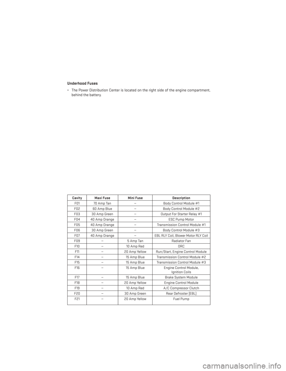
Underhood Fuses
• The Power Distribution Center is located on the right side of the engine compartment,behind the battery.
Cavity Maxi Fuse Mini Fuse Description
F01 70 Amp Tan —Body Control Module #1
F02 60 Amp Blue —Body Control Module #2
F03 30 Amp Green —Output For Starter Relay #1
F04 40 Amp Orange —ESC Pump Motor
F05 40 Amp Orange —Transmission Control Module #1
F06 30 Amp Green —Body Control Module #3
F07 40 Amp Orange — EBL RLY Coil, Blower Motor RLY Coil
F09 —5 Amp Tan Radiator Fan
F10 —10 Amp Red ORC
F11 —20 Amp Yellow Run/Start, Engine Control Module
F14 —15 Amp Blue Transmission Control Module #2
F15 —15 Amp Blue Transmission Control Module #3
F16 —15 Amp Blue Engine Control Module,
Ignition Coils
F17 —15 Amp Blue Brake System Module
F18 —20 Amp Yellow Engine Control Module
F19 —10 Amp Red A/C Compressor Clutch
F20 —30 Amp Green Rear Defroster (EBL)
F21 —20 Amp Yellow Fuel Pump
MAINTAINING YOUR VEHICLE
118
Page 129 of 140
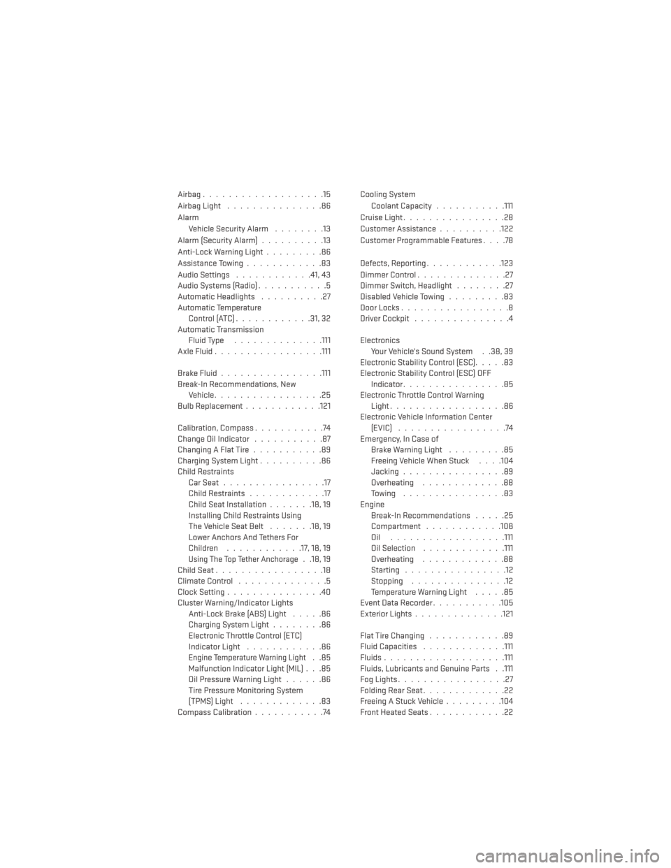
Airbag...................15
Airbag Light...............86
Alarm Vehicle Security Alarm ........13
Alarm (Security Alarm) ..........13
Anti-Lock Warning Light .........86
Assistance Towing ............83
Audio Settings ............41,43
Audio Systems (Radio) ...........5
Automatic Headlights ..........27
Automatic Temperature Control(ATC)............31,32
Automatic Transmission Fluid Type ..............111
AxleFluid................ .111
BrakeFluid................111
Break-In Recommendations, New Vehicle .................25
BulbReplacement............121
Calibration, Compass ...........74
Change Oil Indicator ...........87
Changing A Flat Tire ...........89
Charging System Light ..........86
Child Restraints CarSeat................17
Child Restraints ............17
Child Seat Installation .......18,19
Installing Child Restraints Using
The Vehicle Seat Belt .......18,19
Lower Anchors And Tethers For
Children ............17, 18, 19
Using The Top Tether Anchorage. .18, 19
ChildSeat.................18
ClimateControl ..............5
Clock Setting ...............40
Cluster Warning/Indicator Lights Anti-Lock Brake (ABS) Light .....86
Charging System Light ........86
Electronic Throttle Control (ETC)
Indicator Light ............86
Engine Temperature Warning Light..85
Malfunction Indicator Light (MIL) . . .85
Oil Pressure Warning Light ......86
Tire Pressure Monitoring System
(TPMS) Light .............83
Compass Calibration ...........74 Cooling System
Coolant Capacity ...........111
Cruise Light ................28
Customer Assistance ..........122
Customer Programmable Features ....78
Defects, Reporting ............123
DimmerControl..............27
Dimmer Switch, Headlight ........27
Disabled Vehicle Towing .........83
DoorLocks.................8
Driver Cockpit ...............4
Electronics Your Vehicle's Sound System . .38, 39
Electronic Stability Control (ESC) .....83
Electronic Stability Control (ESC) OFF Indicator ................85
Electronic Throttle Control Warning Light ..................86
Electronic Vehicle Information Center (EVIC) .................74
Emergency, In Case of Brake Warning Light .........85
Freeing Vehicle When Stuck . . . .104
Jacking ................89
Overheating .............88
Towing ................83
Engine Break-In Recommendations .....25
Compartment ............108
Oil ..................111
Oil Selection .............111
Overheating .............88
Starting ................12
Stopping ...............12
Temperature Warning Light .....85
EventDataRecorder...........105
Exterior Lights ..............121
FlatTireChanging ............89
Fluid Capacities .............111
Fluids ...................111
Fluids, Lubricants and Genuine Parts . .111
FogLights.................27
Folding Rear Seat .............22
Freeing A Stuck Vehicle .........104
Front Heated Seats ............22
INDEX
127