warning DODGE DART 2015 PF / 1.G Manual PDF
[x] Cancel search | Manufacturer: DODGE, Model Year: 2015, Model line: DART, Model: DODGE DART 2015 PF / 1.GPages: 664, PDF Size: 16.96 MB
Page 232 of 664
Head Restraints
Head restraints are designed to reduce the risk of injury
by restricting head movement in the event of a rear
impact. Head restraints should be adjusted so that the top
of the head restraint is located above the top of your ear.
WARNING!
The head restraints for all occupants must be prop-
erly installed and adjusted prior to operating the
vehicle or occupying a seat. Head restraints should
never be adjusted while the vehicle is in motion.
Driving a vehicle with the head restraints improperly
adjusted or removed could cause serious injury or
death in the event of a collision.
Reactive Head Restraints — Front Seats
The front driver and passenger seats are equipped with
Reactive Head Restraints (RHR). In the event of a rear
impact the RHRs will automatically extend forward
minimizing the gap between the back of the occupants
head and the RHR.
The RHRs will automatically return to their normal
position following a rear impact. If the RHRs do not
return to their normal position see your authorized
dealer immediately.
To raise the head restraint, pull upward on the head
restraint. To lower the head restraint, press the release
button, located at the base of the head restraint, and push
downward on the head restraint.
230 UNDERSTANDING THE FEATURES OF YOUR VEHICLE
Page 233 of 664
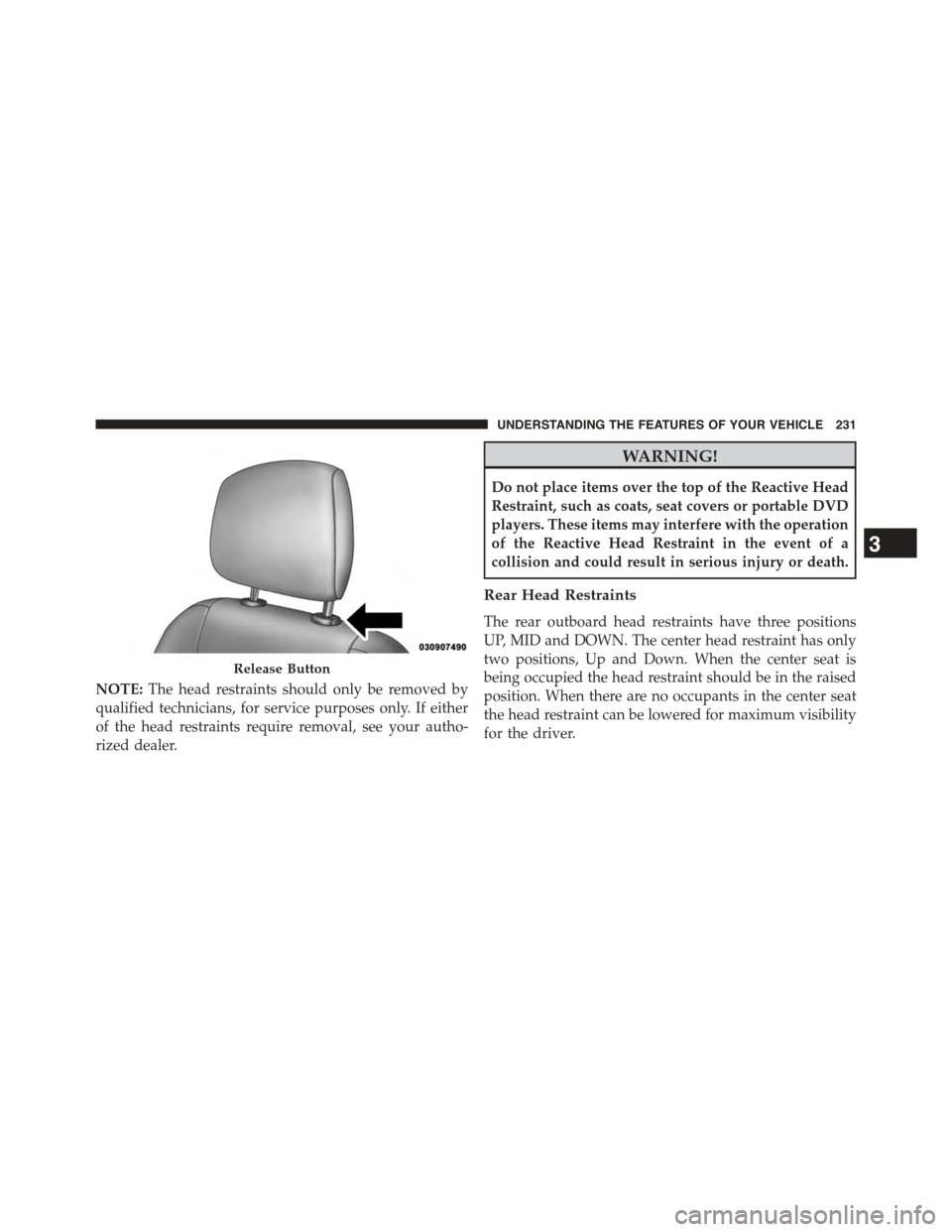
NOTE:The head restraints should only be removed by
qualified technicians, for service purposes only. If either
of the head restraints require removal, see your autho-
rized dealer.
WARNING!
Do not place items over the top of the Reactive Head
Restraint, such as coats, seat covers or portable DVD
players. These items may interfere with the operation
of the Reactive Head Restraint in the event of a
collision and could result in serious injury or death.
Rear Head Restraints
The rear outboard head restraints have three positions
UP, MID and DOWN. The center head restraint has only
two positions, Up and Down. When the center seat is
being occupied the head restraint should be in the raised
position. When there are no occupants in the center seat
the head restraint can be lowered for maximum visibility
for the driver.
Release Button
3
UNDERSTANDING THE FEATURES OF YOUR VEHICLE 231
Page 236 of 664
WARNING!
•Be certain that the seatback is securely locked into
position. If the seatback is not securely locked into
position, the seat will not provide the proper sta-
bility for child seats and/or passengers. An improp-
erly latched seat could cause serious injury.
•The cargo area in the rear of the vehicle (with the
rear seatbacks in the locked-up or folded down
position) should not be used as a play area by
children when the vehicle is in motion. They could
be seriously injured in a collision. Children should
be seated and using the proper restraint system.
TO OPEN AND CLOSE THE HOOD
Two latches must be released to open the hood.
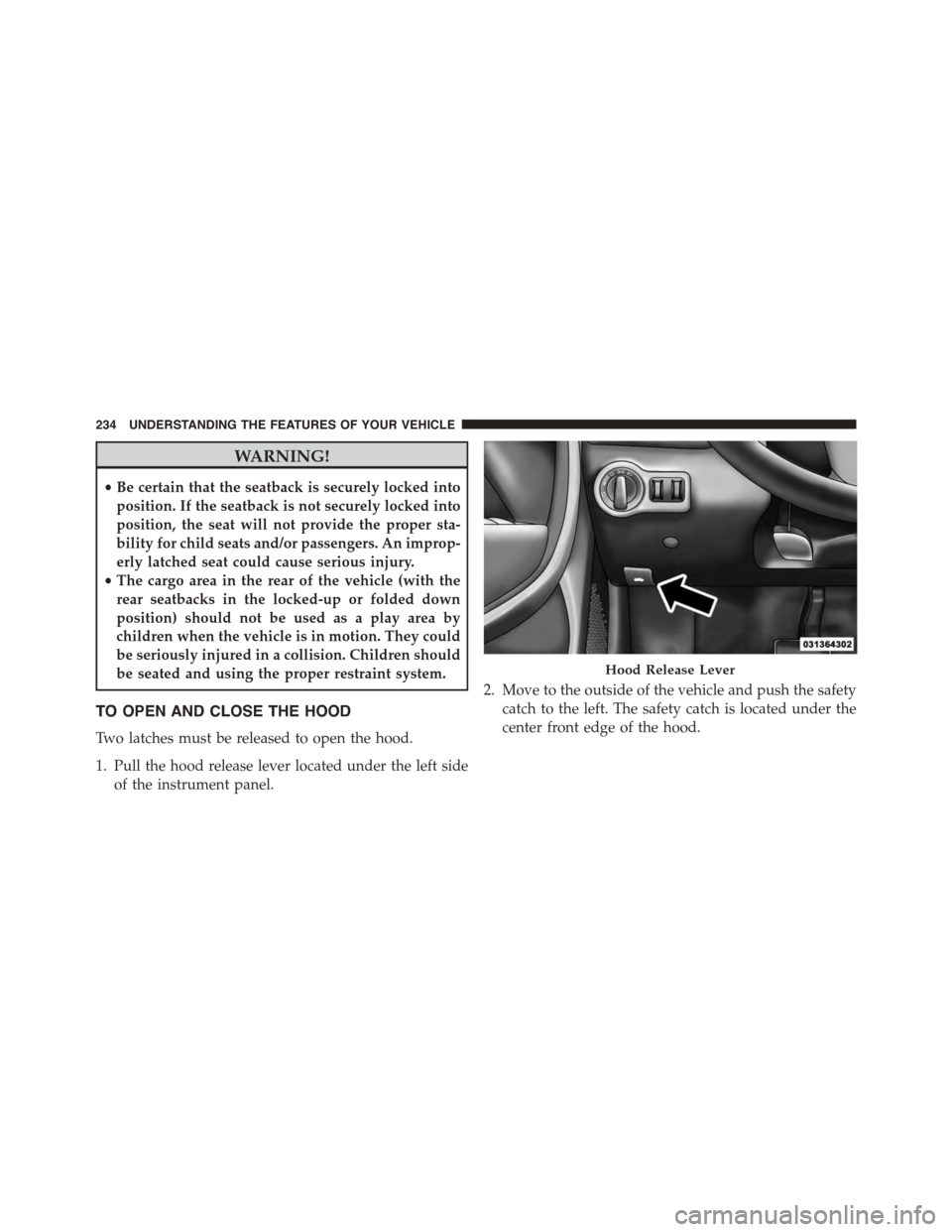
1. Pull the hood release lever located under the left side
of the instrument panel.
2. Move to the outside of the vehicle and push the safety
catch to the left. The safety catch is located under the
center front edge of the hood.
Hood Release Lever
234 UNDERSTANDING THE FEATURES OF YOUR VEHICLE
Page 238 of 664
CAUTION!
To prevent possible damage, do not slam the hood to
close it. Lower the hood until it is open approxi-
mately 6 in (15 cm), and then drop it. This should
(Continued)
CAUTION!(Continued)
secure both latches. Never drive your vehicle unless
the hood is fully closed, with both latches engaged.
WARNING!
Be sure the hood is fully latched before driving your
vehicle. If the hood is not fully latched, it could open
when the vehicle is in motion and block your vision.
Failure to follow this warning could result in serious
injury or death.
LIGHTS
Headlight Switch
The headlight switch is located on the left side of
the instrument panel. This switch controls the
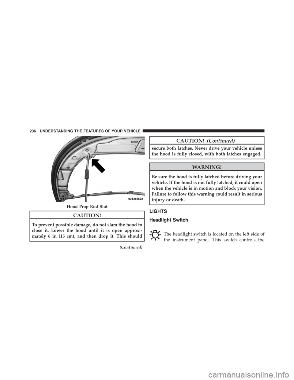
Hood Prop Rod Slot
236 UNDERSTANDING THE FEATURES OF YOUR VEHICLE
Page 250 of 664
Mist Feature
Rotate the end of the lever downward to the Mist
position to activate a single wipe cycle to clear off road
mist or spray from a passing vehicle. The wipers will
continue to operate until you release the multifunction
lever.
NOTE:The mist feature does not activate the washer
pump; therefore, no washer fluid will be sprayed on the
windshield. The wash function must be used in order to
spray the windshield with washer fluid.
Windshield Washers
To use the washer, push the multifunction lever inward
(toward the steering column) and hold it for as long as
washer spray is desired.
If you activate the washer while the windshield wiper
control is in the delay range, the wipers will operate for
two wipe cycles after releasing the lever and then resume
the intermittent interval previously selected.
If you activate the washer while the windshield wiper is
turned off, the wipers will operate for three wipe cycles
and then turn off.
WARNING!
Sudden loss of visibility through the windshield
could lead to a collision. You might not see other
vehicles or other obstacles. To avoid sudden icing of
the windshield during freezing weather, warm the
windshield with the defroster before and during
windshield washer use.
248 UNDERSTANDING THE FEATURES OF YOUR VEHICLE
Page 253 of 664
TILT/TELESCOPING STEERING COLUMN
This feature allows you to tilt the steering column
upward or downward. It also allows you to lengthen or
shorten the steering column. The tilt/telescoping control
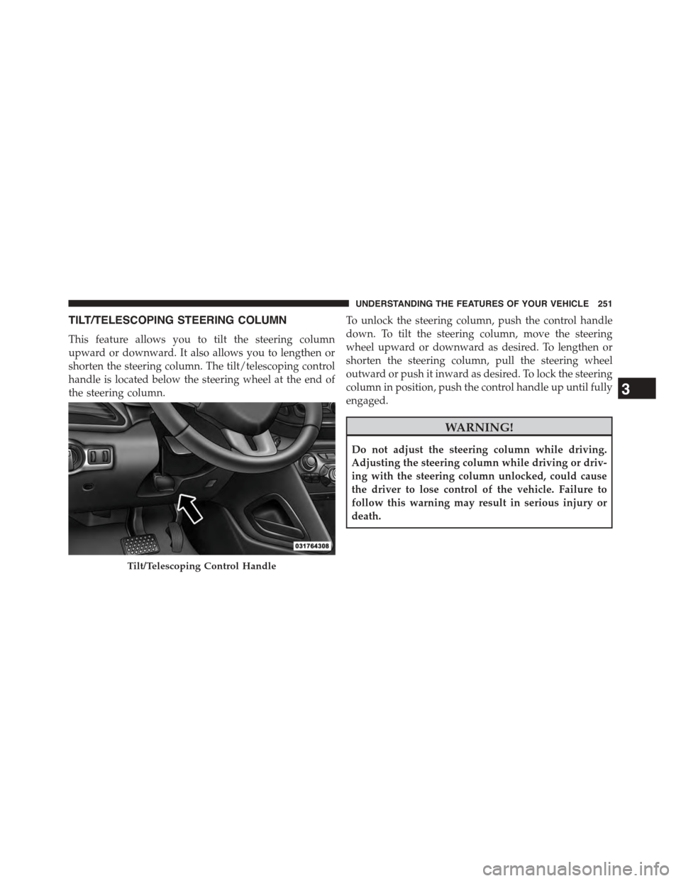
handle is located below the steering wheel at the end of
the steering column.
To unlock the steering column, push the control handle
down. To tilt the steering column, move the steering
wheel upward or downward as desired. To lengthen or
shorten the steering column, pull the steering wheel
outward or push it inward as desired. To lock the steering
column in position, push the control handle up until fully
engaged.
WARNING!
Do not adjust the steering column while driving.
Adjusting the steering column while driving or driv-
ing with the steering column unlocked, could cause
the driver to lose control of the vehicle. Failure to
follow this warning may result in serious injury or
death.
Tilt/Telescoping Control Handle
3
UNDERSTANDING THE FEATURES OF YOUR VEHICLE 251
Page 255 of 664
WARNING!
•Persons who are unable to feel pain to the skin
because of advanced age, chronic illness, diabetes,
spinal cord injury, medication, alcohol use, exhaus-
tion, or other physical conditions must exercise
care when using the steering wheel heater. It may
cause burns even at low temperatures, especially if
used for long periods.
•Do not place anything on the steering wheel that
insulates against heat, such as a blanket or steering
wheel covers of any type and material. This may
cause the steering wheel heater to overheat.
ELECTRONIC SPEED CONTROL — IF EQUIPPED
When engaged, the Electronic Speed Control takes over
accelerator operations at speeds greater than 25 mph
(40 km/h).
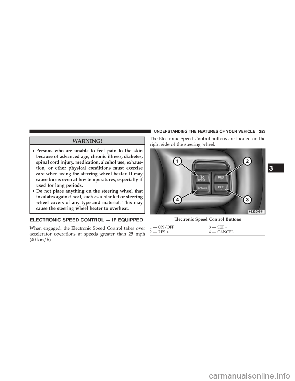
The Electronic Speed Control buttons are located on the
right side of the steering wheel.
Electronic Speed Control Buttons
1—ON/OFF3—SET-2—RES+4—CANCEL
3
UNDERSTANDING THE FEATURES OF YOUR VEHICLE 253
Page 256 of 664
NOTE:In order to ensure proper operation, the Elec-
tronic Speed Control system has been designed to shut
down if multiple Speed Control functions are operated at
the same time. If this occurs, the Electronic Speed Control
system can be reactivated by pushing the Electronic
Speed Control ON/OFF button and resetting the desired
vehicle set speed.
To Activate
Push the ON/OFF button to activate the Electronic Speed
Control. The Cruise Indicator Light in the Electronic
Vehicle Information Center (EVIC) or Driver Information
Display (DID) will illuminate. To turn the system off,
push the ON/OFF button a second time. The Cruise
Indicator Light will turn off. The system should be
turned off when not in use.
WARNING!
Leaving the Electronic Speed Control system on
when not in use is dangerous. You could accidentally
set the system or cause it to go faster than you want.
You could lose control and have an accident. Always
leave the system OFF when you are not using it.
To Set A Desired Speed
Turn the Electronic Speed Control ON.
NOTE:The vehicle should be traveling at a steady speed
and on level ground before pressing the SET button.
When the vehicle has reached the desired speed, press
the SET (-) button and release. Release the accelerator and
the vehicle will operate at the selected speed.
NOTE:After pressing the SET button “Cruise Control
Set” message is displayed for five seconds or until
another switch is pressed.
254 UNDERSTANDING THE FEATURES OF YOUR VEHICLE
Page 259 of 664
•If the button is continually pressed, the set speed will
continue to decrease until the button is released, then
the new set speed will be established.
Metric Speed (km/h)
•Pressing the SET (-) button once will result in a 1 km/h
decrease in set speed. Each subsequent tap of the
button results in a decrease of 1 km/h.
•If the button is continually pressed, the set speed will
continue to decrease until the button is released, then
the new set speed will be established.
To Accelerate For Passing
Press the accelerator as you would normally. When the
pedal is released, the vehicle will return to the set speed.
Using Electronic Speed Control On Hills
The transmission may downshift on hills to maintain the
vehicle set speed.
NOTE:The Electronic Speed Control system maintains
speed up and down hills. A slight speed change on
moderate hills is normal.
On steep hills, a greater speed loss or gain may occur so
it may be preferable to drive without Electronic Speed
Control.
WARNING!
Electronic Speed Control can be dangerous where the
system cannot maintain a constant speed. Your ve-
hicle could go too fast for the conditions, and you
could lose control and have an accident. Do not use
Electronic Speed Control in heavy traffic or on roads
that are winding, icy, snow-covered or slippery.
3
UNDERSTANDING THE FEATURES OF YOUR VEHICLE 257
Page 260 of 664
PARKSENSE® REAR PARK ASSIST — IF
EQUIPPED
The ParkSense® Rear Park Assist system provides visual
and audible indications of the distance between the rear
fascia and a detected obstacle when backing up, e.g.
during a parking maneuver. Refer to “ParkSense® Sys-
tem Usage Precautions” in this section for limitations of
this system and recommendations.
ParkSense® will retain the last system state (enabled or
disabled) from the last ignition cycle when the ignition is
changed to the ON/RUN position.
ParkSense® can be active only when the shift lever is in
REVERSE. If ParkSense® is enabled at this shift lever
position, the system will remain active until the vehicle
speed is increased to approximately 7 mph (11 km/h) or
above. The system will become active again if the vehicle
speed is decreased to speeds less than approximately
6 mph (9 km/h).
ParkSense® Sensors
The four ParkSense® sensors, located in the rear fascia/
bumper, monitor the area behind the vehicle that is
within the sensors’ field of view. The sensors can detect
obstacles from approximately 12 in (30 cm) up to 79 in
(200 cm) from the rear fascia/bumper in the horizontal
direction, depending on the location, type and orienta-
tion of the obstacle.
ParkSense® Warning Display
The ParkSense® Warning screen will only be displayed if
Sound and Display is selected from the Uconnect®
System. Refer to “Uconnect® Settings” in “Understand-
ing Your Instrument Panel” for further information.
The ParkSense® Warning screen is located within the
Driver Information Display (DID). It provides visual
warnings to indicate the distance between the rear
fascia/bumper and the detected obstacle. Refer to
“Driver Information Display (DID) Settings” in “Under-
standing Your Instrument Panel” for further information.
258 UNDERSTANDING THE FEATURES OF YOUR VEHICLE