wheel torque DODGE DART 2015 PF / 1.G Owners Manual
[x] Cancel search | Manufacturer: DODGE, Model Year: 2015, Model line: DART, Model: DODGE DART 2015 PF / 1.GPages: 664, PDF Size: 16.96 MB
Page 458 of 664
WARNING!
BAS cannot prevent the natural laws of physics from
acting on the vehicle, nor can it increase the traction
afforded by prevailing road conditions. BAS cannot
prevent accidents, including those resulting from
excessive speed in turns, driving on very slippery
surfaces, or hydroplaning. The capabilities of a BAS-
equipped vehicle must never be exploited in a reck-
less or dangerous manner, which could jeopardize
the user’s safety or the safety of others.
Traction Control System (TCS)
This system monitors the amount of wheel spin of each of
the driven wheels. If wheel spin is detected, brake
pressure is applied to the slipping wheel(s) and engine
power is reduced to provide enhanced acceleration and
stability. A feature of the TCS system, Brake Limited
Differential (BLD), functions similar to a limited slip
differential and controls the wheel spin across a driven
axle. If one wheel on a driven axle is spinning faster than
the other, the system will apply the brake of the spinning
wheel. This will allow more engine torque to be applied
to the wheel that is not spinning. This feature remains
active even if TCS and ESC are in the “Partial Off” mode.
Refer to “Electronic Stability Control (ESC)” in this
section for more information.
Electronic Roll Mitigation (ERM)
This system anticipates the potential for wheel lift by
monitoring the driver ’s steering wheel input and the
speed of the vehicle. When ERM determines that the rate
of change of the steering wheel angle and vehicle’s speed
are sufficient to potentially cause wheel lift, it then
applies the appropriate brake and may also reduce
engine power to lessen the chance that wheel lift will
occur. ERM will only intervene during very severe or
evasive driving maneuvers.
456 STARTING AND OPERATING
Page 463 of 664
WARNING!(Continued)
•Failure to follow these warnings may cause the
vehicle to roll down the incline and could collide
with another vehicle, object or person, and cause
serious or fatal injury. Always remember to use the
parking brake while parking on a hill and that the
driver is responsible for braking the vehicle.
NOTE:The HSA system may also be turned on and off
if the vehicle is equipped with the Electronic Vehicle
Information Center (EVIC) or Driver Information Display
(DID). Refer to “Electronic Vehicle Information Center
(EVIC) or Driver Information Display (DID)” in “Under-
standing Your Instrument Panel” for further information.
Electronic Stability Control (ESC)
This system enhances directional control and stability of
the vehicle under various driving conditions. ESC cor-
rects for over-steering and under-steering the vehicle by
applying the brake of the appropriate wheel. Engine
power may also be reduced to help the vehicle maintain
the desired path.
ESC reduces engine torque and applies brake pressure to
select individual wheels to mitigate vehicle under-steer
and vehicle over-steer. The system uses engine torque
reduction along with individual wheel brake pressure to
correct under-steer and over-steer conditions.
•Over-steer - when the vehicle is turning more than
appropriate for the steering wheel position.
•Under-steer - when the vehicle is turning less than
appropriate for the steering wheel position.
5
STARTING AND OPERATING 461
Page 527 of 664
WHAT TO DO IN EMERGENCIES
CONTENTS
!HAZARD WARNING FLASHERS...........527
!IF YOUR ENGINE OVERHEATS............527
!WHEEL AND TIRE TORQUE
SPECIFICATIONS......................528
▫Torque Specifications..................528
!TIRE SERVICE KIT — IF EQUIPPED.........530
▫Tire Service Kit Storage.................530
▫Tire Service Kit Components And Operation . .530
▫Tire Service Kit Usage Precautions..........531
▫Sealing A Tire With Tire Service Kit.........534
!JACKING AND TIRE CHANGING..........539
▫Jack Location/Spare Tire Stowage —
If Equipped.........................540
▫Preparations For Jacking................542
▫Jacking And Changing A Tire.............543
▫Road Tire Installation...................548
!JUMP-STARTING PROCEDURES...........551
▫Preparations For Jump-Start..............551
▫Jump-Starting Procedure................553
!FREEING A STUCK VEHICLE.............555
6
Page 530 of 664
CAUTION!
Driving with a hot cooling system could damage
your vehicle. If the temperature gauge reads “H,”
pull over and stop the vehicle. Idle the vehicle with
the air conditioner turned off until the pointer drops
back into the normal range. If the pointer remains on
the “H,” turn the engine off immediately and call for
service.
WARNING!
You or others can be badly burned by hot engine
coolant (antifreeze) or steam from your radiator. If
you see or hear steam coming from under the hood,
do not open the hood until the radiator has had time
to cool. Never try to open a cooling system pressure
cap when the radiator or coolant bottle is hot.
WHEEL AND TIRE TORQUE SPECIFICATIONS
Proper lug nut/bolt torque is very important to ensure
that the wheel is properly mounted to the vehicle. Any
time a wheel has been removed and reinstalled on the
vehicle the lug nuts/bolts should be torqued using a
properly calibrated torque wrench.
Torque Specifications
Lug Nut/Bolt Torque **Lug Nut/
Bolt Size
Lug Nut/
Bolt
Socket
Size
100 Ft-Lbs (135 N·m) M12 x 1.25 19 mm
**Use only Chrysler recommended lug nuts/bolts and
clean or remove any dirt or oil before tightening.
Inspect the wheel mounting surface prior to mounting
the tire and remove any corrosion or loose particles.
528 WHAT TO DO IN EMERGENCIES
Page 531 of 664
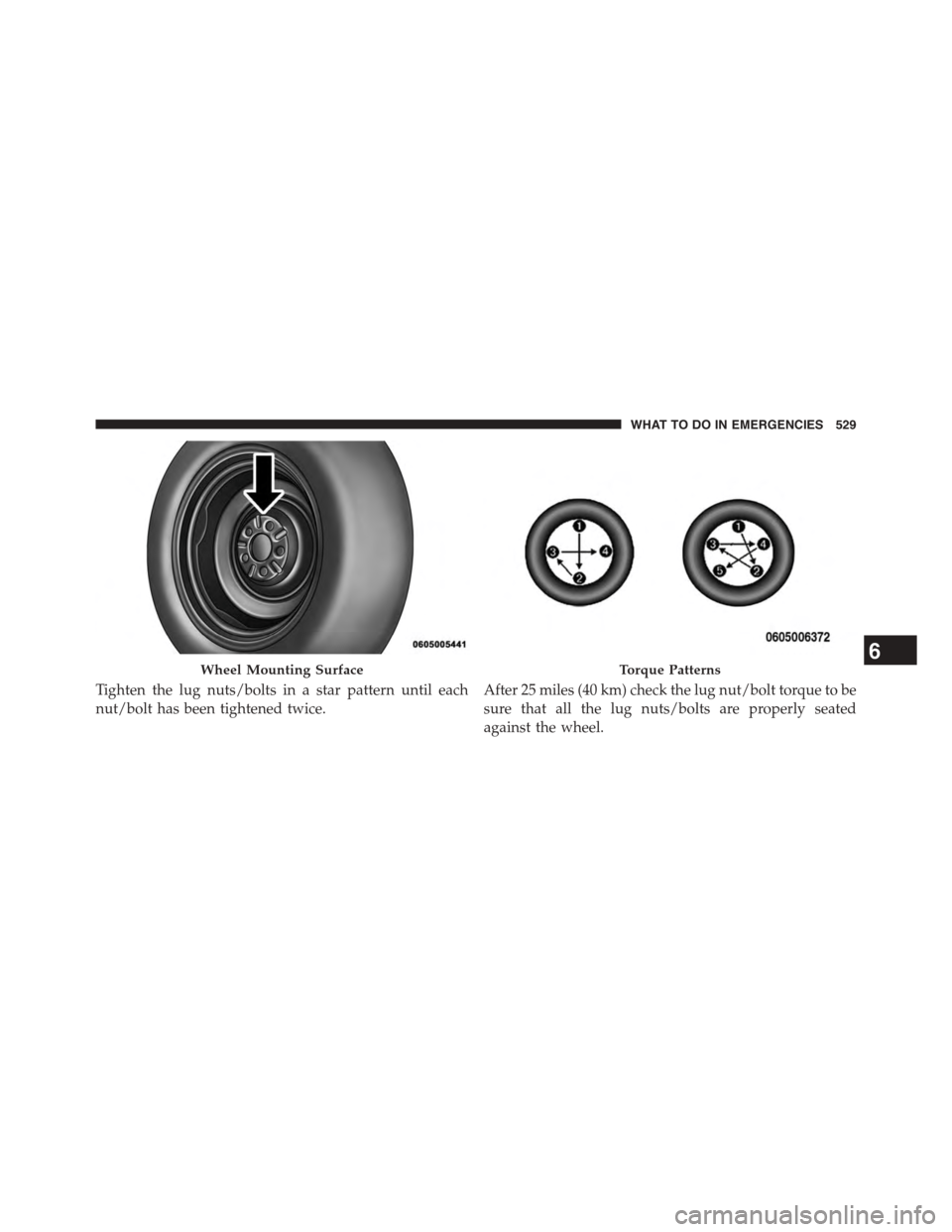
Tighten the lug nuts/bolts in a star pattern until each
nut/bolt has been tightened twice.
After 25 miles (40 km) check the lug nut/bolt torque to be
sure that all the lug nuts/bolts are properly seated
against the wheel.
Wheel Mounting SurfaceTorque Patterns6
WHAT TO DO IN EMERGENCIES 529
Page 550 of 664
9. Lower the vehicle to the ground by turning the jack
handle counterclockwise.
10. Finish tightening the wheel bolts. Push down on the
wrench while at the end of the handle for increased
leverage. Tighten the wheel bolts in a star pattern
until each wheel bolt has been tightened twice. Refer
to “Torque Specifications” in this section for proper
lug bolt torque. If in doubt about the correct tight-
ness, have them checked with a torque wrench by
your authorized dealer or at a service station.
11. Lower the jack until it is free. Remove the wheel
blocks. Reassemble the lug wrench to the jack assem-
bly and stow it in the spare tire area. Secure the
assembly using the means provided. Release the
parking brake before driving the vehicle.
12. Stow the jack, tools and flat tire.
WARNING!
A loose tire or jack thrown forward in a collision or
hard stop could endanger the occupants of the ve-
hicle. Always stow the jack parts and the spare tire in
the places provided. Have the deflated (flat) tire
repaired or replaced immediately.
Road Tire Installation
Vehicles Equipped With Wheel Covers
1. Mount the road tire on the axle.
2. To ease the installation process for steel wheels with
wheel covers, install two wheel bolts on the wheel
which are on each side of the valve stem. Install the
wheel bolts with the threaded end of the bolt toward
the wheel. Lightly tighten the wheel bolts.
548 WHAT TO DO IN EMERGENCIES
Page 552 of 664
“Torque Specifications” in this section for proper lug
bolt torque. If in doubt about the correct tightness,
have them checked with a torque wrench by your
authorized dealer or service station.
7. Lower the jack until it is free. Remove the wheel
blocks. Reassemble the lug wrench to the jack assem-
bly and stow it in the spare tire area. Secure the
assembly using the means provided. Release the park-
ing brake before driving the vehicle.
8. After 25 miles (40 km) check the wheel bolt torque
with a torque wrench to ensure that all wheel bolts are
properly seated against the wheel.
Road Tire Installation
1. Mount the road tire on the axle.
2. Install the remaining wheel bolts with the threaded
end of the wheel bolt toward the wheel. Lightly
tighten the wheel bolts.
WARNING!
To avoid the risk of forcing the vehicle off the jack,
do not tighten the lug nuts fully until the vehicle has
been lowered. Failure to follow this warning may
result in personal injury.
3. Lower the vehicle to the ground by turning the jack
handle counterclockwise.
4. Finish tightening the wheel bolts. Push down on the
wrench while at the end of the handle for increased
leverage. Tighten the wheel bolts in a star pattern until
each wheel bolt has been tightened twice. Refer to
“Torque Specifications” in this section for the proper
lug bolt torque. If in doubt about the correct tightness,
have them checked with a torque wrench by your
authorized dealer or service station.
550 WHAT TO DO IN EMERGENCIES
Page 553 of 664
5. Lower the jack until it is free. Remove the wheel
blocks. Reassemble the lug wrench to the jack assem-
bly and stow it in the spare tire area. Secure the
assembly using the means provided. Release the park-
ing brake before driving the vehicle.
6. After 25 miles (40 km) check the wheel bolt torque
with a torque wrench to ensure that all wheel bolts are
properly seated against the wheel.
JUMP-STARTING PROCEDURES
If your vehicle has a discharged battery it can be jump-
started using a set of jumper cables and a battery in
another vehicle or by using a portable battery booster
pack. Jump-starting can be dangerous if done improperly
so please follow the procedures in this section carefully.
NOTE:When using a portable battery booster pack
follow the manufacturer ’s operating instructions and
precautions.
CAUTION!
Do not use a portable battery booster pack or any
other booster source with a system voltage greater
than 12 Volts or damage to the battery, starter motor,
alternator or electrical system may occur.
WARNING!
Do not attempt jump-starting if the battery is frozen.
It could rupture or explode and cause personal injury.
Preparations For Jump-Start
The battery in your vehicle is located in the front of the
engine compartment, behind the left headlight assembly.
NOTE:The positive battery post is covered with a
protective cap. Lift up on the cap to gain access to the
positive battery post.
6
WHAT TO DO IN EMERGENCIES 551