warning DODGE DART 2015 PF / 1.G Owner's Manual
[x] Cancel search | Manufacturer: DODGE, Model Year: 2015, Model line: DART, Model: DODGE DART 2015 PF / 1.GPages: 164, PDF Size: 25.19 MB
Page 48 of 164
NOTE:
If three consecutive sunroof close attempts result in Pinch Protect reversals, the fourth
close attempt will be a Manual Close movement with Pinch Protect disabled.
WARNING!
•Donotletchildrenplaywiththesunroof.Neverleavechildrenunattendedina
vehicle, or with access to an unlocked vehicle. Do not leave the Key Fob in or near
the vehicle, and do not leave the ignition of a vehicle equipped with Keyless
Enter-N-Go™ in the ACC or ON/RUN mode. Occupants, particularly unattended
children, can become entrapped by the power sunroof while operating the power
sunroof switch. Such entrapment may result in serious injury or death.
•Inacollision,thereisagreaterriskofbeingthrownfromavehiclewithanopen
sunroof. You could also be severely injured or killed. Always fasten your seat belt
properly and make sure all passengers are properly secured.
•Donotallowsmallchildrentooperatethesunroof.Neverallowyourfingers,other
body parts, or any object to project through the sunroof opening. Injury may result.
MANUAL TRANSMISSION — IF EQUIPPED
Be sure the transmission is in first gear, not third, when starting from a standing position.
Damage to the clutch can result from starting in third gear.
Never drive with your foot resting on the clutch pedal, and never try to hold the vehicle on
ahillwiththeclutchpedalpartiallyengaged.Thiswillcauseabnormalwearontheclutch.
Shifting Into Reverse
To s h i f t i n t o R e v e r s e p u l l u p o n t h e l o c k o u t r i n g ( l o c a t e d u n d e r t h e s h i f t k n o b ) a n d s h i f t t h e
transmission into Reverse.
NOTE:
•NevershiftintoREVERSEuntilthevehiclehascometoacompletestop.
•Duringcoldweather,untilthetransmissionlubricantiswarm,youmayexperience
slightly higher shift efforts. This is normal and not harmful to the transmission.
OPERATING YOUR VEHICLE
46
Page 49 of 164
SIX-SPEED AUTOMATIC TRANSMISSION
This vehicle may be equipped with a fuel efficient Dual-Dry Clutch, Six Speed Automatic
Tr a n s m i s s i o n . T h i s t r a n s m i s s i o n o f f e r s a s p o r t i e r d r i v i n g e x p e r i e n c e w i t h f a s t e r A u t o S t i c k®
shifting.
During low-speed driving conditions in first gear, vehicle momentum changes may feel
exaggerated in response to changes in accelerator pedal position. This behavior is normal
and is similar to vehicles equipped with a manual transmission.
NOTE:
•Veryaggressivedrivingmayresultinsomeclutchodorsimilartoamanualtransmis-
sion. An active warning message will display in the Instrument Cluster if cool down
actions are needed.
•Thefirstfewshiftsonanewvehiclemaybesomewhatabrupt.Thisisanormal
condition, and precision shifts will develop within a few hundred miles (kilometers).
•Atlowspeedsyoumayhearmechanicalnoisessimilartoamanualtransmissionasthe
transmission changes gears. These noises are normal and will not damage the
transmission.
•Beforeandaftertheengineisstarted,youmayhearahydraulicpumpforashortperiod
of time. This noise is normal and will not damage the transmission.
Shifting The Transmission
The transmission shift lever position (PRND) is displayed both on the shift lever and in the
Electronic Vehicle Information Center (EVIC).
To d r i v e , d e p r e s s t h e b r a k e p e d a l , p r e s s t h e b u t t o n o n t h e f r o n t o f t h e s h i f t l e v e r a n d m o v e
the shift lever from PARK or NEUTRAL to the DRIVE position.
Manual shifts can also be made using the AutoStick®shift control.
This transmission is programmed to prevent shifting from Reverse to Drive or Drive to
Reverse, if vehicle speed is above 6 mph (10 km/h). This safety feature helps protect your
transmission from damage.
NOTE:
•Whenstoppedonanincline,itisrecommendedthatyoualwaysholdthevehiclein
place using the brakes. On steep inclines, Hill Start Assist (HSA) will temporarily hold
the car in position when the brake pedal is released. If the accelerator pedal is not
applied after a short time, the car will roll back. Either reapply the brake (to hold the
vehicle) or press the accelerator to climb the hill.
•Duringacceleration,gearchangeswillfeelsmoothcomparedtoavehiclewitha
traditional manual transmission. This is a benefit of the dual clutch design that avoids
power loss during up-shifts.
OPERATING YOUR VEHICLE
47
Page 64 of 164
WARNING!
•Anyvoicecommandedsystemshouldbeusedonlyinsafedrivingconditions
following applicable laws regarding phone use. Your attention should be focused on
safely operating the vehicle. Failure to do so may result in a collision causing you
and others to be severely injured or killed.
•Inanemergency,touseUconnect®Phone, your mobile phone must be:
•turnedon,
•pairedtoUconnect®Phone,
•andhavenetworkcoverage.
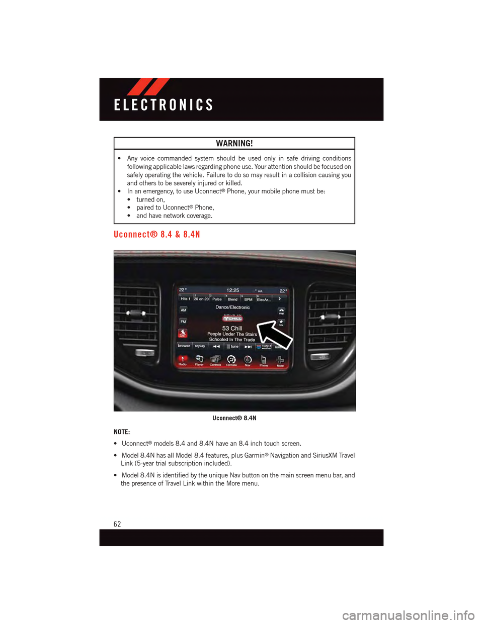
Uconnect® 8.4 & 8.4N
NOTE:
•Uconnect®models 8.4 and 8.4N have an 8.4 inch touch screen.
•Model8.4NhasallModel8.4features,plusGarmin®Navigation and SiriusXM Travel
Link (5-year trial subscription included).
•Model8.4NisidentifiedbytheuniqueNavbuttononthemainscreenmenubar,and
the presence of Travel Link within the More menu.
Uconnect® 8.4N
ELECTRONICS
62
Page 90 of 164
The following chart lists the navigation voice commands that may be available.
Navigation Voice Commands:
“Where To?” (Main Menu command)“View Map” (Main Menu command)“Repeat guidance”“Cancel Route”“Detour” (During a Route Guidance)“Where Am I?”“Find Address”“Go Home”“Find Place by Category”“Find Place by Name”“Find Recently Found”“Find Favorite”“Find City”“Find Nearest Restaurant”“Find Nearest Fuel”
“Find Nearest Transit”“Find Nearest Lodging”“Find Nearest Shopping”“Find Nearest Bank”“Find Nearest Parking”“Find Nearest Entertainment”“Find Nearest Recreation”“Find Nearest Attractions”“Find Nearest Hospitals”“Find Nearest Community”“Find Nearest Auto Services”“Find Nearest Airport”“Find Nearest Police Stations”“Find Nearest Fire Stations”“Find Nearest Auto Dealers”
WARNING!
•Anyvoicecommandedsystemshouldbeusedonlyinsafedrivingconditions
following applicable laws regarding phone use. Your attention should be focused on
safely operating the vehicle. Failure to do so may result in a collision causing you
and others to be severely injured or killed.
•Inanemergency,touseUconnect®Phone, your mobile phone must be:
•turnedon,
•pairedtoUconnect®Phone,
•andhavenetworkcoverage.
STEERING WHEEL AUDIO CONTROLS
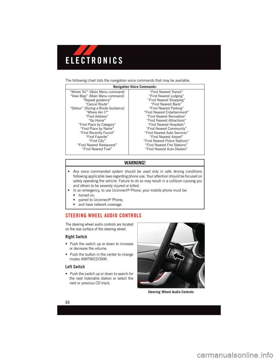
The steering wheel audio controls are located
on the rear surface of the steering wheel.
Right Switch
•Pushtheswitchupordowntoincrease
or decrease the volume.
•Pushthebuttoninthecentertochange
modes AM/FM/CD/SXM.
Left Switch
•Pushtheswitchupordowntosearchfor
the next listenable station or select the
next or previous CD track.
Steering Wheel Audio Controls
ELECTRONICS
88
Page 92 of 164
DRIVER INFORMATION DISPLAY (DID) — PREMIUM (4 BUTTON)
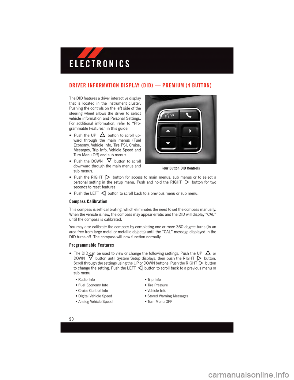
The DID features a driver interactive display
that is located in the instrument cluster.
Pushing the controls on the left side of the
steering wheel allows the driver to select
vehicle information and Personal Settings.
For additional information, refer to “Pro-
grammable Features” in this guide.
•PushtheUPbutton to scroll up-
ward through the main menus (Fuel
Economy, Vehicle Info, Tire PSI, Cruise,
Messages, Trip Info, Vehicle Speed and
Tu r n M e n u O f f ) a n d s u b m e n u s .
•PushtheDOWNbutton to scroll
downward through the main menus and
sub menus.
•PushtheRIGHTbutton for access to main menus, sub menus or to select a
personal setting in the setup menu. Push and hold the RIGHTbutton for two
seconds to reset features
•PushtheLEFTbutton to scroll back to a previous menu or sub menu.
Compass Calibration
This compass is self-calibrating, which eliminates the need to set the compass manually.
When the vehicle is new, the compass may appear erratic and the DID will display “CAL”
until the compass is calibrated.
Yo u m a y a l s o c a l i b r a t e t h e c o m p a s s b y c o m p l e t i n g o n e o r m o r e 3 6 0 d e g r e e t u r n s ( i n a n
area free from large metal or metallic objects) until the “CAL” message displayed in the
DID turns off. The compass will now function normally.
Programmable Features
•TheDIDcanbeusedtovieworchangethefollowingsettings.PushtheUPor
DOWNbutton until System Setup displays, then push the RIGHTbutton.
Scroll through the settings using the UP or DOWN buttons. Push the RIGHTbutton
to change the setting. Push the LEFTbutton to scroll back to a previous menu or
sub menu.
•RadioInfo•TripInfo
•FuelEconomyInfo•TirePressure
•CruiseControlInfo•VehicleInfo
•DigitalVehicleSpeed•StoredWarningMessages
•AnalogVehicleSpeed•TurnMenuOFF
Four Button DID Controls
ELECTRONICS
90
Page 94 of 164
Trip Info
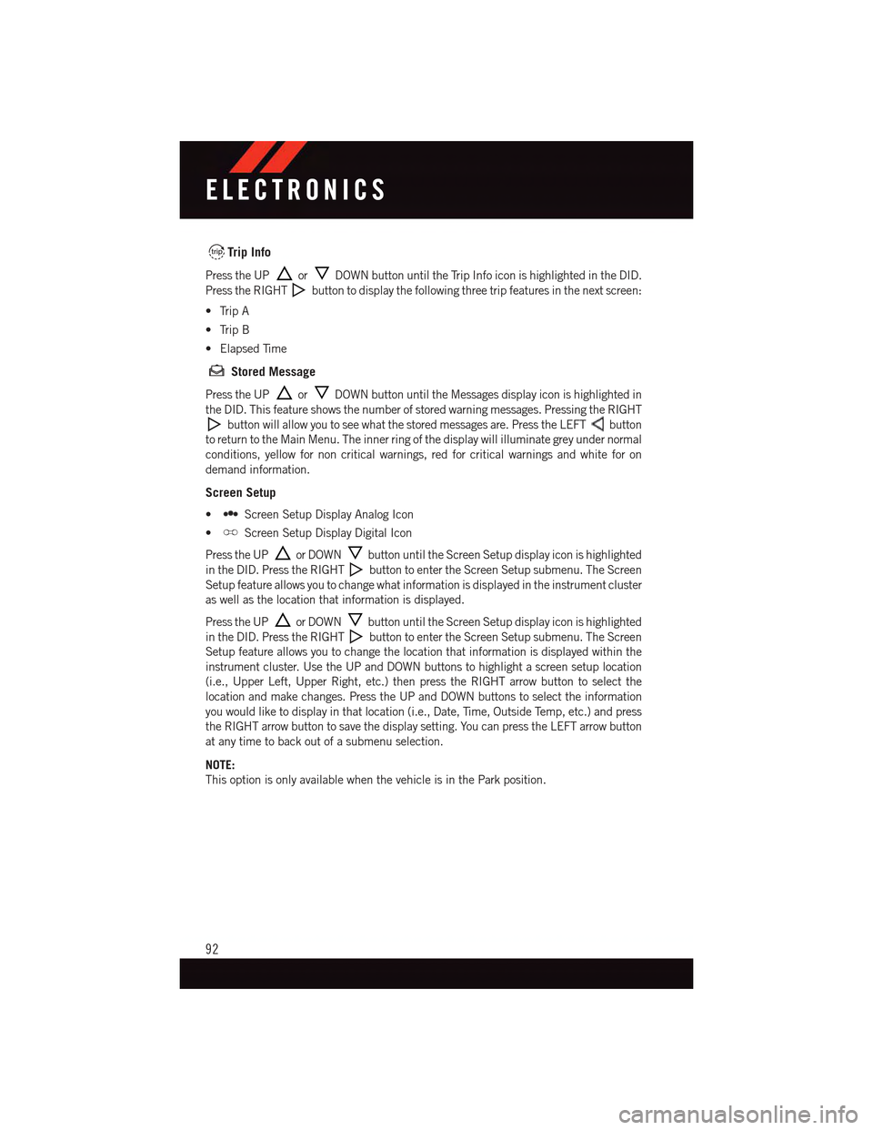
Press the UPorDOWN button until the Trip Info icon is highlighted in the DID.
Press the RIGHTbutton to display the following three trip features in the next screen:
•TripA
•TripB
•ElapsedTime
Stored Message
Press the UPorDOWN button until the Messages display icon is highlighted in
the DID. This feature shows the number of stored warning messages. Pressing the RIGHT
button will allow you to see what the stored messages are. Press the LEFTbutton
to return to the Main Menu. The inner ring of the display will illuminate grey under normal
conditions, yellow for non critical warnings, red for critical warnings and white for on
demand information.
Screen Setup
•Screen Setup Display Analog Icon
•Screen Setup Display Digital Icon
Press the UPor DOWNbutton until the Screen Setup display icon is highlighted
in the DID. Press the RIGHTbutton to enter the Screen Setup submenu. The Screen
Setup feature allows you to change what information is displayed in the instrument cluster
as well as the location that information is displayed.
Press the UPor DOWNbutton until the Screen Setup display icon is highlighted
in the DID. Press the RIGHTbutton to enter the Screen Setup submenu. The Screen
Setup feature allows you to change the location that information is displayed within the
instrument cluster. Use the UP and DOWN buttons to highlight a screen setup location
(i.e., Upper Left, Upper Right, etc.) then press the RIGHT arrow button to select the
location and make changes. Press the UP and DOWN buttons to select the information
you would like to display in that location (i.e., Date, Time, Outside Temp, etc.) and press
the RIGHT arrow button to save the display setting. You can press the LEFT arrow button
at any time to back out of a submenu selection.
NOTE:
This option is only available when the vehicle is in the Park position.
ELECTRONICS
92
Page 98 of 164
Programming A Non-Rolling Code
For programming Garage Door Openers manufactured before 1995.
1. Turn the ignition switch to the ON/RUN position.
2. Place the hand-held transmitter 1 to 3 inches (3 to 8 cm) away from the HomeLink®
button you want to program while keeping the HomeLink®indicator light in view.
3. Push and hold the HomeLink®button you want to program while you push and hold
the hand-held transmitter button.
4. Continue to hold both buttons and observe the indicator light. The Homelink®
indicator will flash slowly and then rapidly after Homelink®has received the frequency
signal from the hand-held transmitter. Release both buttons after the indicator light
changes from slow to rapid.
5. Press and hold the programmed HomeLink®button and observe the indicator light.
•Iftheindicatorlightstaysonconstantly,programmingiscompleteandthegarage
door (or device) should activate when the HomeLink®button is pressed.
To p r o g r a m t h e t w o r e m a i n i n g H o m e L i n k®buttons, repeat each step for each remaining
button. DO NOT erase the channels.
Using HomeLink®
To o p e r a t e , p u s h a n d r e l e a s e t h e p r o g r a m m e d H o m e L i n k®button. Activation will now
occur for the programmed device (e.g., garage door opener, gate operator, security system,
entry door lock, home/office lighting, etc.). The hand-held transmitter of the device may
also be used at any time.
WARNING!
•Yourmotorizeddoororgatewillopenandclosewhileyouareprogrammingthe
universal transceiver. Do not program the transceiver if people or pets are in the
path of the door or gate.
•Donotrunyourvehicleinaclosedgarageorconfinedareawhileprogrammingthe
transceiver. Exhaust gas from your vehicle contains Carbon Monoxide (CO) which is
odorless and colorless. Carbon Monoxide is poisonous when inhaled and can cause
you and others to be severely injured or killed.
ELECTRONICS
96
Page 102 of 164
ROADSIDE ASSISTANCE
Dial toll-free 1-800-521-2779 for U.S. Residents or 1-800-363-4869 for Canadian
Residents.
•Provideyourname,vehicleidentificationnumber,licenseplatenumber,andyour
location, including the telephone number from which you are calling.
•Brieflydescribethenatureoftheproblemandanswerafewsimplequestions.
•Youwillbegiventhenameoftheserviceproviderandanestimatedtimeofarrival.If
you feel you are in an “unsafe situation”, please let us know. With your consent, we will
contact local police or safety authorities.
INSTRUMENT CLUSTER WARNING LIGHTS
-ElectronicStabilityControl(ESC)Activation/MalfunctionIndicatorLight
The “ESC Activation/Malfunction Indicator Light” in the instrument cluster will come on
when the ignition switch is turned to the ON/RUN position. It should go out with the
engine running. If the “ESC Activation/Malfunction Indicator Light” comes on continu-
ously with the engine running, a malfunction has been detected in the ESC system.
If this light remains on after several ignition cycles, and the vehicle has been driven
several miles (kilometers) at speeds greater than 30 mph (48 km/h), we recommend you
drive to the nearest service center and have the vehicle serviced immediately.
-TirePressureMonitoringSystem(TPMS)Light
Each tire, including the spare (if provided), should be checked monthly when cold and
inflated to the inflation pressure recommended by the vehicle manufacturer on the
vehicle placard or tire inflation pressure label. (If your vehicle has tires of a different size
than the size indicated on the vehicle placard or tire inflation pressure label, you should
determine the proper tire inflation pressure for those tires.)
As an added safety feature, your vehicle has been equipped with a tire pressure
monitoring system (TPMS) that illuminates a low tire pressure telltale when one or more
of your tires is significantly under-inflated. Accordingly, when the low tire pressure telltale
illuminates, you should stop and check your tires as soon as possible, and inflate them to
the proper pressure. Driving on a significantly under-inflated tire causes the tire to
overheat and can lead to tire failure. Under-inflation also reduces fuel efficiency and tire
tread life, and may affect the vehicle’s handling and stopping ability.
IF THE LIGHT STARTS FLASHING INDICATING A LOW TIRE PRESSURE, ADJUST THE AIR
PRESSURE IN THE LOW TIRE TO THE AIR PRESSURE SHOWN ON THE VEHICLE PLACARD OR
TIRE INFLATION PRESSURE LABEL LOCATED ON THE DRIVER'S DOOR.
WHAT TO DO IN EMERGENCIES
100
Page 103 of 164
NOTE:
AFTER INFLATION, THE VEHICLE MAY NEED TO BE DRIVEN FOR 20 MINUTES
BEFORE THE FLASHING LIGHT WILL TURN OFF.
Please note that the TPMS is not a substitute for proper tire maintenance, and it is the
driver’s responsibility to maintain correct tire pressure, even if under-inflation has not
reached the level to trigger illumination of the TPMS low tire pressure telltale.
Yo u r v e h i c l e h a s a l s o b e e n e q u i p p e d w i t h a T P M S m a l f u n c t i o n i n d i c a t o r t o i n d i c a t e w h e n
the system is not operating properly. The TPMS malfunction indicator is combined with
the low tire pressure telltale.
When the system detects a malfunction, the telltale will flash for approximately one
minute and then remain continuously illuminated. This sequence will continue upon
subsequent vehicle start-ups as long as the malfunction exists. When the malfunction
indicator is illuminated, the system may not be able to detect or signal low tire pressure
as intended. TPMS malfunctions may occur for a variety of reasons, including the
installation of replacement or alternate tires or wheels on the vehicle that prevent the
TPMS from functioning properly. Always check the TPMS malfunction telltale after
replacing one or more tires or wheels on your vehicle to ensure that the replacement or
alternate tires and wheels allow the TPMS to continue to function properly.
NOTE:
Ti r e p r e s s u r e s c h a n g e b y a p p r o x i m a t e l y 1 p s i ( 7 k P a ) p e r 1 2 ° F ( 7 ° C ) o f a i r t e m p e r a t u r e
change. Keep this in mind when checking tire pressure inside a garage, especially in the
Winter. Example: If garage temperature is 68°F (20°C) and the outside temperature is
32°F (0°C), then the cold tire inflation pressure should be increased by 3 psi (21 kPa),
which equals 1 psi (7 kPa) for every 12°F (7°C) for this outside temperature condition.
CAUTION!
The TPMS has been optimized for the original equipment tires and wheels. TPMS
pressures and warning have been established for the tire size equipped on your vehicle.
Undesirable system operation or sensor damage may result when using replacement
equipment that is not of the same size, type, and/or style. Aftermarket wheels can
cause sensor damage. Do not use tire sealant from a can, or balance beads if your
vehicle is equipped with a TPMS, as damage to the sensors may result.
WHAT TO DO IN EMERGENCIES
101
Page 104 of 164
-EngineTemperatureWarningLight
This light warns of an overheated engine condition.
If the light turns on or flashes continuously while driving, safely pull over and stop the
vehicle. If the A/C system is on, turn it off. Also, shift the transmission into NEUTRAL and
idle the vehicle. If the temperature reading does not return to normal, turn the engine off
immediately.
We recommend that you do not operate the vehicle or engine damage will occur. Have the
vehicle serviced immediately.
WARNING!
Ahotenginecoolingsystemisdangerous.Youorotherscouldbebadlyburnedby
steam or boiling coolant.
-BrakeWarningLight
This light monitors various brake functions, including brake fluid level and parking brake
application. If the brake light turns on it may indicate that the parking brake is applied,
that the brake fluid level is low, or that there is a problem with the anti-lock brake system
reservoir.
If the light remains on when the parking brake has been disengaged, and the fluid level is
at the full mark on the master cylinder reservoir, it indicates a possible brake hydraulic
system malfunction or that a problem with the Brake Booster has been detected by the
Anti-Lock Brake System (ABS)/Electronic Stability Control (ESC) system. In this case, the
light will remain on until the condition has been corrected. If the problem is related to the
brake booster, the ABS pump will run when applying the brake and a brake pedal
pulsation may be felt during each stop.
The dual brake system provides a reserve braking capacity in the event of a failure to a
portion of the hydraulic system. A leak in either half of the dual brake system is indicated
by the Brake Warning Light, which will turn on when the brake fluid level in the master
cylinder has dropped below a specified level. The light will remain on until the cause is
corrected.
Vehicles equipped with the Anti-Lock Brake System (ABS), are also equipped with
Electronic Brake Force Distribution (EBD). In the event of an EBD failure, the Brake
Warning Light will turn on along with the ABS Light. Immediate repair to the ABS system
is required.
Operation of the Brake Warning Light can be checked by turning the ignition switch from
the OFF position to the ON/RUN position. The light should illuminate for approximately
two seconds. The light should then turn off unless the parking brake is applied or a brake
fault is detected. If the light does not illuminate, have the light inspected by an authorized
dealer.
WHAT TO DO IN EMERGENCIES
102