Park light DODGE DART 2015 PF / 1.G User Guide
[x] Cancel search | Manufacturer: DODGE, Model Year: 2015, Model line: DART, Model: DODGE DART 2015 PF / 1.GPages: 164, PDF Size: 25.19 MB
Page 15 of 164
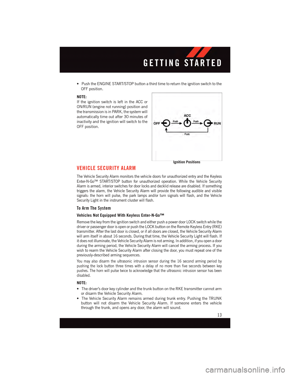
•PushtheENGINESTART/STOPbuttonathirdtimetoreturntheignitionswitchtothe
OFF position.
NOTE:
If the ignition switch is left in the ACC or
ON/RUN (engine not running) position and
the transmission is in PARK, the system will
automatically time out after 30 minutes of
inactivity and the ignition will switch to the
OFF position.
VEHICLE SECURITY ALARM
The Vehicle Security Alarm monitors the vehicle doors for unauthorized entry and the Keyless
Enter-N-Go™ START/STOP button for unauthorized operation. While the Vehicle SecurityAlarm is armed, interior switches for door locks and decklid release are disabled. If somethingtriggers the alarm, the Vehicle Security Alarm will provide the following audible and visiblesignals: the horn will pulse, the park lamps and/or turn signals will flash, and the VehicleSecurity Light in the instrument cluster will flash.
To Arm The System
Vehicles Not Equipped With Keyless Enter-N-Go™
Remove the key from the ignition switch and either push a power door LOCK switch while thedriver or passenger door is open or push the LOCK button on the Remote Keyless Entry (RKE)transmitter. After the last door is closed, or if all doors are closed, the Vehicle Security Alarmwill arm itself in about 16 seconds. During that time, the Vehicle Security Light will flash. Ifit does not illuminate, the Vehicle Security Alarm is not arming. In addition, if you open a doorduring the arming period, the Vehicle Security Alarm will cancel the arming process. If youwish to rearm the Vehicle Security Alarm after closing the door, you must repeat one of thepreviously-described arming sequences.
Yo u m a y a l s o d i s a r m t h e u l t r a s o n i c i n t r u s i o n s e n s o r d u r i n g t h e 1 6 s e c o n d a r m i n g p e r i o d b ypushing the lock button three times with a delay of no more than five seconds between keypushes. The horn will pulse twice to acknowledge that the ultrasonic intrusion sensor has beendisabled.
NOTE:
•Thedriver’sdoorkeycylinderandthetrunkbuttonontheRKEtransmittercannotarmor disarm the Vehicle Security Alarm.
•TheVehicleSecurityAlarmremainsarmedduringtrunkentry.PushingtheTRUNKbutton will not disarm the Vehicle Security Alarm. If someone enters the vehiclethrough the trunk, and opens any door, the alarm will sound.
Ignition Positions
GETTING STARTED
13
Page 37 of 164
HEADLIGHT SWITCH
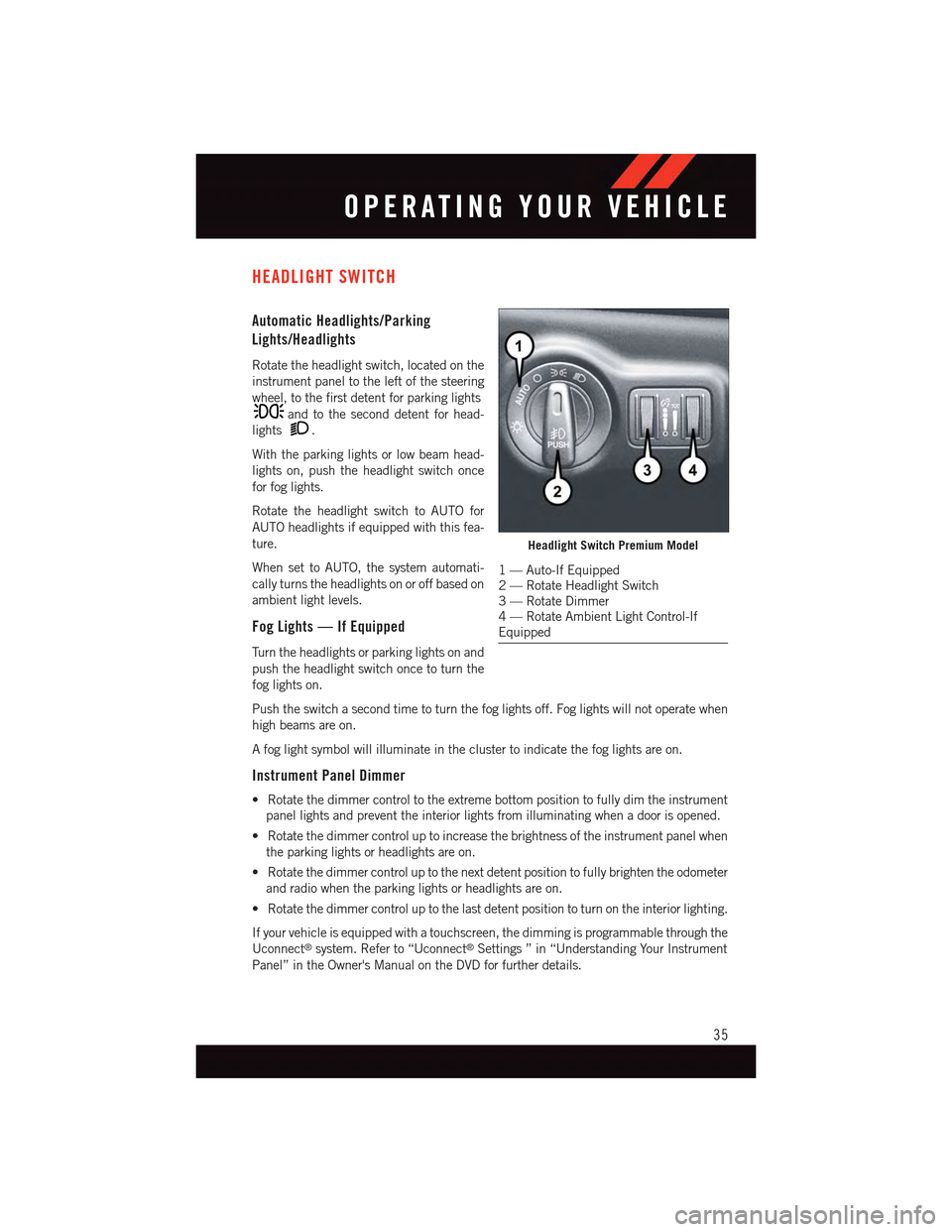
Automatic Headlights/Parking
Lights/Headlights
Rotate the headlight switch, located on the
instrument panel to the left of the steering
wheel, to the first detent for parking lights
and to the second detent for head-
lights.
With the parking lights or low beam head-
lights on, push the headlight switch once
for fog lights.
Rotate the headlight switch to AUTO for
AUTO headlights if equipped with this fea-
ture.
When set to AUTO, the system automati-
cally turns the headlights on or off based on
ambient light levels.
Fog Lights — If Equipped
Tu r n t h e h e a d l i g h t s o r p a r k i n g l i g h t s o n a n d
push the headlight switch once to turn the
fog lights on.
Push the switch a second time to turn the fog lights off. Fog lights will not operate when
high beams are on.
Afoglightsymbolwillilluminateintheclustertoindicatethefoglightsareon.
Instrument Panel Dimmer
•Rotatethedimmercontroltotheextremebottompositiontofullydimtheinstrument
panel lights and prevent the interior lights from illuminating when a door is opened.
•Rotatethedimmercontroluptoincreasethebrightnessoftheinstrumentpanelwhen
the parking lights or headlights are on.
•Rotatethedimmercontroluptothenextdetentpositiontofullybrightentheodometer
and radio when the parking lights or headlights are on.
•Rotatethedimmercontroluptothelastdetentpositiontoturnontheinteriorlighting.
If your vehicle is equipped with a touchscreen, the dimming is programmable through the
Uconnect®system. Refer to “Uconnect®Settings ” in “Understanding Your Instrument
Panel” in the Owner's Manual on the DVD for further details.
Headlight Switch Premium Model
1—Auto-IfEquipped2—RotateHeadlightSwitch3—RotateDimmer4—RotateAmbientLightControl-IfEquipped
OPERATING YOUR VEHICLE
35
Page 46 of 164
BLIND SPOT MONITORING
The Blind Spot Monitoring (BSM) system uses two radar-based sensors, located inside the
rear bumper fascia, to detect Highway licensable vehicles (automobiles, trucks, motor-
cycles etc.) that enter the blind spot zones from the rear/front/side of the vehicle.
The Blind Spot Monitoring (BSM) system warning light, located in the outside mirrors, will
illuminate if a vehicle moves into a blind spot zone.
The BSM system can also be configured to sound an audible (chime) alert and mute the
radio to notify you of objects that have entered the detection zones.
Refer to your Owner's Manual on the DVD for further details.
PARKVIEW® REAR BACK-UP CAMERA
Yo u c a n s e e a n o n - s c r e e n i m a g e o f t h e r e a r o f y o u r v e h i c l e w h e n e v e r t h e s h i f t l e v e r i s p u t
into REVERSE. The ParkView®Rear Back-Up Camera image will be displayed on the radio
display screen, located on the center stack of the instrument panel.
If the radio display screen appears foggy, clean the camera lens located on the rear of the
vehicle above the rear license plate.
Refer to your Owner's Manual on the DVD for further details.
WARNING!
Drivers must be careful when backing up; even when using the ParkView®Rear
Back-Up Camera. Always check carefully behind your vehicle, and be sure to check for
pedestrians, animals, other vehicles, obstructions, or blind spots before backing up.
Yo u m u s t c o n t i n u e t o p a y a t t e n t i o n w h i l e b a c k i n g u p . F a i l u r e t o d o s o c a n r e s u l t i n
serious injury or death.
WIND BUFFETING
Wind buffeting can be described as a helicopter-type percussion sound. If buffeting
occurs with the rear windows open, adjust the front and rear windows together.
If buffeting occurs with the sunroof open, adjust the sunroof opening, or adjust any
window. This will minimize buffeting.
OPERATING YOUR VEHICLE
44
Page 94 of 164
Trip Info
Press the UPorDOWN button until the Trip Info icon is highlighted in the DID.
Press the RIGHTbutton to display the following three trip features in the next screen:
•TripA
•TripB
•ElapsedTime
Stored Message
Press the UPorDOWN button until the Messages display icon is highlighted in
the DID. This feature shows the number of stored warning messages. Pressing the RIGHT
button will allow you to see what the stored messages are. Press the LEFTbutton
to return to the Main Menu. The inner ring of the display will illuminate grey under normal
conditions, yellow for non critical warnings, red for critical warnings and white for on
demand information.
Screen Setup
•Screen Setup Display Analog Icon
•Screen Setup Display Digital Icon
Press the UPor DOWNbutton until the Screen Setup display icon is highlighted
in the DID. Press the RIGHTbutton to enter the Screen Setup submenu. The Screen
Setup feature allows you to change what information is displayed in the instrument cluster
as well as the location that information is displayed.
Press the UPor DOWNbutton until the Screen Setup display icon is highlighted
in the DID. Press the RIGHTbutton to enter the Screen Setup submenu. The Screen
Setup feature allows you to change the location that information is displayed within the
instrument cluster. Use the UP and DOWN buttons to highlight a screen setup location
(i.e., Upper Left, Upper Right, etc.) then press the RIGHT arrow button to select the
location and make changes. Press the UP and DOWN buttons to select the information
you would like to display in that location (i.e., Date, Time, Outside Temp, etc.) and press
the RIGHT arrow button to save the display setting. You can press the LEFT arrow button
at any time to back out of a submenu selection.
NOTE:
This option is only available when the vehicle is in the Park position.
ELECTRONICS
92
Page 96 of 164
Uconnect® 8.4 CUSTOMER PROGRAMMABLE FEATURES
The Uconnect®8.4 system allows you to access Customer Programmable feature settings
such as Display, Clock, Safety/Assistance, Lights, Doors & Locks, Heated Seats, Engine
Off Operation, Compass Settings, Audio, Phone/Bluetooth®and SiriusXM Setup through
buttons on the touchscreen.
Press the “More” button on the touchscreen on the bottom of the screen, then press the
“Settings” button on the touchscreen to access the Settings screen. When making a
selection, scroll up or down until the preferred setting is highlighted, then press and
release the preferred setting until a check-mark appears next to the setting, showing that
setting has been selected. The following feature settings are available:
•Display•Clock
•Safety/Assistance•Lights
•Doors&Locks•Auto-OnComfort&RemoteStart
•EngineOffOptions•CompassSettings
•Audio•Phone/Bluetooth®
•SiriusXMSetup
UNIVERSAL GARAGE DOOR OPENER (HomeLink®)
HomeLink®replaces up to three hand-held transmitters that operate devices such as
garage door openers, motorized gates, lighting or home security systems. The HomeLink®
unit is powered by your vehicles 12 Volt battery.
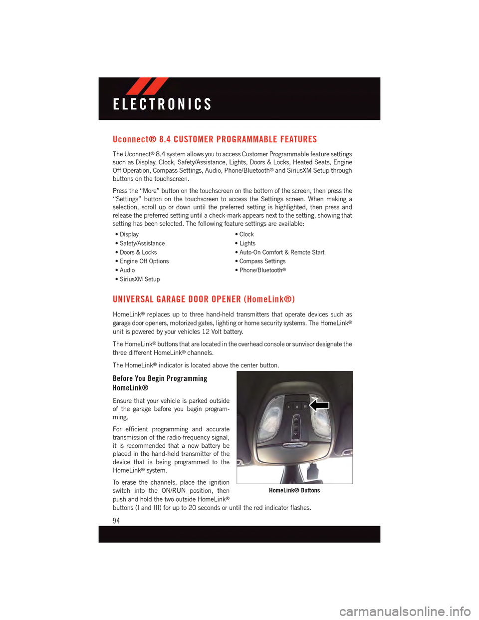
The HomeLink®buttons that are located in the overhead console or sunvisor designate the
three different HomeLink®channels.
The HomeLink®indicator is located above the center button.
Before You Begin Programming
HomeLink®
Ensure that your vehicle is parked outside
of the garage before you begin program-
ming.
For efficient programming and accurate
transmission of the radio-frequency signal,
it is recommended that a new battery be
placed in the hand-held transmitter of the
device that is being programmed to the
HomeLink®system.
To e r a s e t h e c h a n n e l s , p l a c e t h e i g n i t i o n
switch into the ON/RUN position, then
push and hold the two outside HomeLink®
buttons (I and III) for up to 20 seconds or until the red indicator flashes.
HomeLink® Buttons
ELECTRONICS
94
Page 104 of 164
-EngineTemperatureWarningLight
This light warns of an overheated engine condition.
If the light turns on or flashes continuously while driving, safely pull over and stop the
vehicle. If the A/C system is on, turn it off. Also, shift the transmission into NEUTRAL and
idle the vehicle. If the temperature reading does not return to normal, turn the engine off
immediately.
We recommend that you do not operate the vehicle or engine damage will occur. Have the
vehicle serviced immediately.
WARNING!
Ahotenginecoolingsystemisdangerous.Youorotherscouldbebadlyburnedby
steam or boiling coolant.
-BrakeWarningLight
This light monitors various brake functions, including brake fluid level and parking brake
application. If the brake light turns on it may indicate that the parking brake is applied,
that the brake fluid level is low, or that there is a problem with the anti-lock brake system
reservoir.
If the light remains on when the parking brake has been disengaged, and the fluid level is
at the full mark on the master cylinder reservoir, it indicates a possible brake hydraulic
system malfunction or that a problem with the Brake Booster has been detected by the
Anti-Lock Brake System (ABS)/Electronic Stability Control (ESC) system. In this case, the
light will remain on until the condition has been corrected. If the problem is related to the
brake booster, the ABS pump will run when applying the brake and a brake pedal
pulsation may be felt during each stop.
The dual brake system provides a reserve braking capacity in the event of a failure to a
portion of the hydraulic system. A leak in either half of the dual brake system is indicated
by the Brake Warning Light, which will turn on when the brake fluid level in the master
cylinder has dropped below a specified level. The light will remain on until the cause is
corrected.
Vehicles equipped with the Anti-Lock Brake System (ABS), are also equipped with
Electronic Brake Force Distribution (EBD). In the event of an EBD failure, the Brake
Warning Light will turn on along with the ABS Light. Immediate repair to the ABS system
is required.
Operation of the Brake Warning Light can be checked by turning the ignition switch from
the OFF position to the ON/RUN position. The light should illuminate for approximately
two seconds. The light should then turn off unless the parking brake is applied or a brake
fault is detected. If the light does not illuminate, have the light inspected by an authorized
dealer.
WHAT TO DO IN EMERGENCIES
102
Page 105 of 164
The light also will turn on when the parking brake is applied with the ignition switch in the
ON/RUN position.
NOTE:
This light shows only that the parking brake is applied. It does not show the degree of
brake application.
WARNING!
Driving a vehicle with the red brake light on is dangerous. Part of the brake system may
have failed. It will take longer to stop the vehicle. You could have a collision. Have the
vehicle checked immediately.
-MalfunctionIndicatorLight(MIL)
Certain conditions, such as a loose or missing gas cap, poor fuel quality, etc., may
illuminate the MIL after engine start. The vehicle should be serviced if the light stays on
through several typical driving cycles. In most situations, the vehicle will drive normally
and not require towing.
If the MIL flashes when the engine is running, serious conditions may exist that could lead
to immediate loss of power or severe catalytic converter damage. We recommend you do
not operate the vehicle. Have the vehicle serviced immediately.
-ElectronicStabilityControl(ESC)OFFIndicatorLight
This light indicates the Electronic Stability Control (ESC) is off.
-ChargingSystemLight
This light shows the status of the electrical charging system. If the charging system light
remains on, it means that the vehicle is experiencing a problem with the charging system.
We recommend you do not continue driving if the charging system light is on. Have the
vehicle serviced immediately.
-OilPressureWarningLight
This light indicates low engine oil pressure. If the light turns on while driving, stop the
vehicle and shut off the engine as soon as possible. A chime will sound when this light
turns on.
We recommend you do not operate the vehicle or engine damage will occur. Have the
vehicle serviced immediately.
-Anti-LockBrake(ABS)Light
This light monitors the Anti-Lock Brake System (ABS).
If the light is not on during starting, stays on, or turns on while driving, we recommend you
contact the nearest authorized dealer and have the vehicle serviced immediately.
WHAT TO DO IN EMERGENCIES
103
Page 106 of 164
-ElectronicThrottleControl(ETC)IndicatorLight
This light informs you of a problem with the system.
If a problem is detected, the light will come on while the engine is running. Cycle the
ignition when the vehicle has completely stopped and the shift lever is placed in the PARK
position; the light should turn off.
If the light remains lit with the engine running, your vehicle will usually be drivable;
however, see an authorized dealer immediately. If the light is flashing when the engine is
running, immediate service is required and you may experience reduced performance, an
elevated/rough idle or engine stall and your vehicle may require towing.
-AirBagWarningLight
If the light is not on during starting, stays on, or turns on while driving, have the vehicle
serviced by an authorized dealer immediately.
Fuel Cap/Loose Gas Cap Message
•Ifa“gascap”message(shownasCheckFuelCap)appears,tightenthegascapuntil
a“clicking”soundisheard.
•Presstheodometerresetbuttontoturnthemessageoff.
•Ifthemessagecontinuestoappearformorethanthreedaysaftertighteningthegas
cap, see your authorized service center.
Oil Change Indicator
•Yourvehicleisequippedwithanengineoilchangeindicatorsystem.The“OilChange
Due” message will flash in the EVIC display for approximately 10 seconds after a single
chime has sounded, to indicate the next scheduled oil change interval. The engine oil
change indicator system is duty cycle based, which means the engine oil change
interval may fluctuate, dependent upon your personal driving style.
•Unlessreset,thismessagewillcontinuetodisplayeachtimeyouturntheignition
switch to the ON/RUN position or cycle the ignition to the ON/RUN position if equipped
with Keyless Enter-N-Go™. To turn off the message temporarily, press and release the
MENU button. To reset the oil change indicator system (after performing the scheduled
maintenance) refer to the following procedure.
Vehicles Equipped With Keyless Enter-N-Go™
1. Without pressing the brake pedal, cycle the ignition to the ON/RUN position (do not
start the engine).
2. Fully depress the accelerator pedal, slowly, three times within 10 seconds.
3. Cycle the ignition to the OFF/LOCK position.
WHAT TO DO IN EMERGENCIES
104
Page 122 of 164
JUMP-STARTING
If your vehicle has a discharged battery it
can be jump-started using a set of jumper
cables and a battery in another vehicle or by
using a portable battery booster pack.
Jump-starting can be dangerous if done
improperly so please follow the procedures
in this section carefully.
NOTE:
When using a portable battery booster pack
follow the manufacturer’s operating instruc-
tions and precautions.
Preparations For Jump-Start
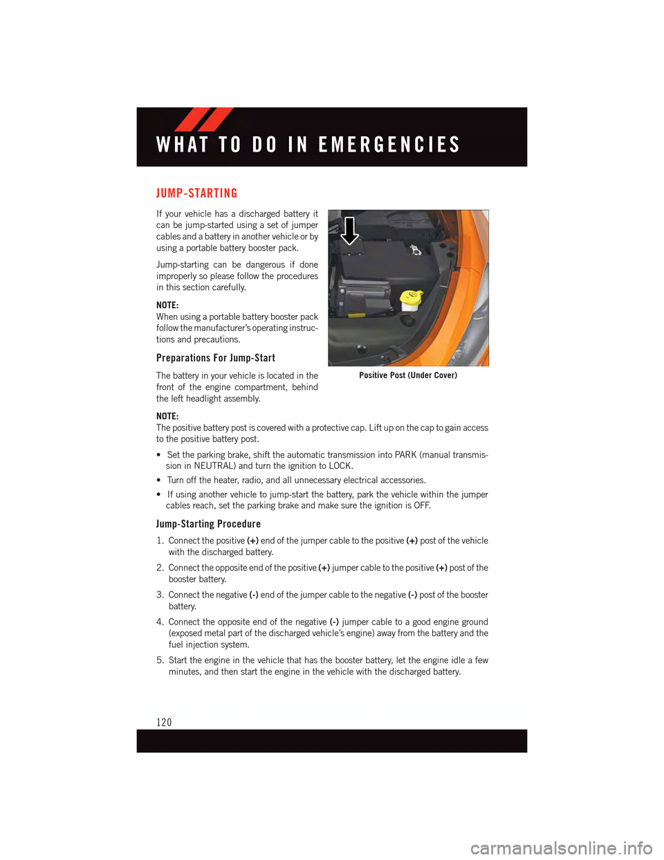
The battery in your vehicle is located in the
front of the engine compartment, behind
the left headlight assembly.
NOTE:
The positive battery post is covered with a protective cap. Lift up on the cap to gain access
to the positive battery post.
•Settheparkingbrake,shifttheautomatictransmissionintoPARK(manualtransmis-
sion in NEUTRAL) and turn the ignition to LOCK.
•Turnofftheheater,radio,andallunnecessaryelectricalaccessories.
•Ifusinganothervehicletojump-startthebattery,parkthevehiclewithinthejumper
cables reach, set the parking brake and make sure the ignition is OFF.
Jump-Starting Procedure
1. Connect the positive(+)end of the jumper cable to the positive(+)post of the vehicle
with the discharged battery.
2. Connect the opposite end of the positive(+)jumper cable to the positive(+)post of the
booster battery.
3. Connect the negative(-)end of the jumper cable to the negative(-)post of the booster
battery.
4. Connect the opposite end of the negative(-)jumper cable to a good engine ground
(exposed metal part of the discharged vehicle’s engine) away from the battery and the
fuel injection system.
5. Start the engine in the vehicle that has the booster battery, let the engine idle a few
minutes, and then start the engine in the vehicle with the discharged battery.
Positive Post (Under Cover)
WHAT TO DO IN EMERGENCIES
120
Page 151 of 164
AUTHENTIC ACCESSORIES BY MOPAR®
•ThefollowinghighlightsjustsomeofthemanyAuthenticDodgeAccessoriesby
Mopar®featuring a fit, finish, and functionality specifically for your Dodge Dart.
•InchoosingAuthenticAccessoriesyougainfarmorethanexpressivestyle,premium
protection, or extreme entertainment, you also benefit from enhancing your vehicle
with accessories that have been thoroughly tested and factory-approved.
•ForthefulllineofAuthenticDodgeAccessoriesbyMopar®,visityourlocaldealership
or online at mopar.com for U.S. residents and mopar.ca for Canadian residents.
NOTE:
All parts are subject to availability.
EXTERIOR:
•FrontChinSpoiler •ChromeDoorHandles •ChromeGrilleInsert
•RearAirDiffuser •TurnSignalMirrors •SideSills
INTERIOR:
•PremiumCarpetFloorMats•DoorSillGuards •Emergency/FirstAidKit
•SlushMats •Trunk/CargoMat •RearCargoOrganizer
•LeatherWrappedShiftKnob
ELECTRONICS:
•Mopar®Web (WiFi) • Trunk Lid Light Bar • Park Distance Sensors
•KickerSpeakerUpgrades •WirelessCharging(MobilePhone)•ElectronicVehicleTrackingSystem
•RemoteStart •Interior/AmbientLighting
CARRIERS:
•Hitch-MountBikeCarrier •RoofBoxCargoCarrier •RoofMountBikeCarrier
•RoofMountSkiandSnow-board Carrier•RoofMountWaterSportsCarrier•HitchReceiver
•RoofRack
MOPAR® ACCESSORIES
149