brake light DODGE DART 2015 PF / 1.G User Guide
[x] Cancel search | Manufacturer: DODGE, Model Year: 2015, Model line: DART, Model: DODGE DART 2015 PF / 1.GPages: 164, PDF Size: 25.19 MB
Page 104 of 164
-EngineTemperatureWarningLight
This light warns of an overheated engine condition.
If the light turns on or flashes continuously while driving, safely pull over and stop the
vehicle. If the A/C system is on, turn it off. Also, shift the transmission into NEUTRAL and
idle the vehicle. If the temperature reading does not return to normal, turn the engine off
immediately.
We recommend that you do not operate the vehicle or engine damage will occur. Have the
vehicle serviced immediately.
WARNING!
Ahotenginecoolingsystemisdangerous.Youorotherscouldbebadlyburnedby
steam or boiling coolant.
-BrakeWarningLight
This light monitors various brake functions, including brake fluid level and parking brake
application. If the brake light turns on it may indicate that the parking brake is applied,
that the brake fluid level is low, or that there is a problem with the anti-lock brake system
reservoir.
If the light remains on when the parking brake has been disengaged, and the fluid level is
at the full mark on the master cylinder reservoir, it indicates a possible brake hydraulic
system malfunction or that a problem with the Brake Booster has been detected by the
Anti-Lock Brake System (ABS)/Electronic Stability Control (ESC) system. In this case, the
light will remain on until the condition has been corrected. If the problem is related to the
brake booster, the ABS pump will run when applying the brake and a brake pedal
pulsation may be felt during each stop.
The dual brake system provides a reserve braking capacity in the event of a failure to a
portion of the hydraulic system. A leak in either half of the dual brake system is indicated
by the Brake Warning Light, which will turn on when the brake fluid level in the master
cylinder has dropped below a specified level. The light will remain on until the cause is
corrected.
Vehicles equipped with the Anti-Lock Brake System (ABS), are also equipped with
Electronic Brake Force Distribution (EBD). In the event of an EBD failure, the Brake
Warning Light will turn on along with the ABS Light. Immediate repair to the ABS system
is required.
Operation of the Brake Warning Light can be checked by turning the ignition switch from
the OFF position to the ON/RUN position. The light should illuminate for approximately
two seconds. The light should then turn off unless the parking brake is applied or a brake
fault is detected. If the light does not illuminate, have the light inspected by an authorized
dealer.
WHAT TO DO IN EMERGENCIES
102
Page 105 of 164
The light also will turn on when the parking brake is applied with the ignition switch in the
ON/RUN position.
NOTE:
This light shows only that the parking brake is applied. It does not show the degree of
brake application.
WARNING!
Driving a vehicle with the red brake light on is dangerous. Part of the brake system may
have failed. It will take longer to stop the vehicle. You could have a collision. Have the
vehicle checked immediately.
-MalfunctionIndicatorLight(MIL)
Certain conditions, such as a loose or missing gas cap, poor fuel quality, etc., may
illuminate the MIL after engine start. The vehicle should be serviced if the light stays on
through several typical driving cycles. In most situations, the vehicle will drive normally
and not require towing.
If the MIL flashes when the engine is running, serious conditions may exist that could lead
to immediate loss of power or severe catalytic converter damage. We recommend you do
not operate the vehicle. Have the vehicle serviced immediately.
-ElectronicStabilityControl(ESC)OFFIndicatorLight
This light indicates the Electronic Stability Control (ESC) is off.
-ChargingSystemLight
This light shows the status of the electrical charging system. If the charging system light
remains on, it means that the vehicle is experiencing a problem with the charging system.
We recommend you do not continue driving if the charging system light is on. Have the
vehicle serviced immediately.
-OilPressureWarningLight
This light indicates low engine oil pressure. If the light turns on while driving, stop the
vehicle and shut off the engine as soon as possible. A chime will sound when this light
turns on.
We recommend you do not operate the vehicle or engine damage will occur. Have the
vehicle serviced immediately.
-Anti-LockBrake(ABS)Light
This light monitors the Anti-Lock Brake System (ABS).
If the light is not on during starting, stays on, or turns on while driving, we recommend you
contact the nearest authorized dealer and have the vehicle serviced immediately.
WHAT TO DO IN EMERGENCIES
103
Page 106 of 164
-ElectronicThrottleControl(ETC)IndicatorLight
This light informs you of a problem with the system.
If a problem is detected, the light will come on while the engine is running. Cycle the
ignition when the vehicle has completely stopped and the shift lever is placed in the PARK
position; the light should turn off.
If the light remains lit with the engine running, your vehicle will usually be drivable;
however, see an authorized dealer immediately. If the light is flashing when the engine is
running, immediate service is required and you may experience reduced performance, an
elevated/rough idle or engine stall and your vehicle may require towing.
-AirBagWarningLight
If the light is not on during starting, stays on, or turns on while driving, have the vehicle
serviced by an authorized dealer immediately.
Fuel Cap/Loose Gas Cap Message
•Ifa“gascap”message(shownasCheckFuelCap)appears,tightenthegascapuntil
a“clicking”soundisheard.
•Presstheodometerresetbuttontoturnthemessageoff.
•Ifthemessagecontinuestoappearformorethanthreedaysaftertighteningthegas
cap, see your authorized service center.
Oil Change Indicator
•Yourvehicleisequippedwithanengineoilchangeindicatorsystem.The“OilChange
Due” message will flash in the EVIC display for approximately 10 seconds after a single
chime has sounded, to indicate the next scheduled oil change interval. The engine oil
change indicator system is duty cycle based, which means the engine oil change
interval may fluctuate, dependent upon your personal driving style.
•Unlessreset,thismessagewillcontinuetodisplayeachtimeyouturntheignition
switch to the ON/RUN position or cycle the ignition to the ON/RUN position if equipped
with Keyless Enter-N-Go™. To turn off the message temporarily, press and release the
MENU button. To reset the oil change indicator system (after performing the scheduled
maintenance) refer to the following procedure.
Vehicles Equipped With Keyless Enter-N-Go™
1. Without pressing the brake pedal, cycle the ignition to the ON/RUN position (do not
start the engine).
2. Fully depress the accelerator pedal, slowly, three times within 10 seconds.
3. Cycle the ignition to the OFF/LOCK position.
WHAT TO DO IN EMERGENCIES
104
Page 122 of 164
JUMP-STARTING
If your vehicle has a discharged battery it
can be jump-started using a set of jumper
cables and a battery in another vehicle or by
using a portable battery booster pack.
Jump-starting can be dangerous if done
improperly so please follow the procedures
in this section carefully.
NOTE:
When using a portable battery booster pack
follow the manufacturer’s operating instruc-
tions and precautions.
Preparations For Jump-Start
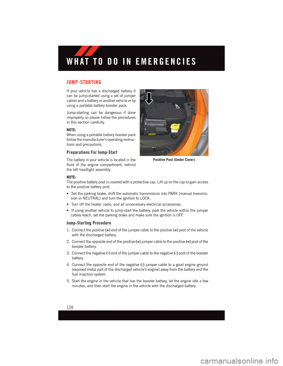
The battery in your vehicle is located in the
front of the engine compartment, behind
the left headlight assembly.
NOTE:
The positive battery post is covered with a protective cap. Lift up on the cap to gain access
to the positive battery post.
•Settheparkingbrake,shifttheautomatictransmissionintoPARK(manualtransmis-
sion in NEUTRAL) and turn the ignition to LOCK.
•Turnofftheheater,radio,andallunnecessaryelectricalaccessories.
•Ifusinganothervehicletojump-startthebattery,parkthevehiclewithinthejumper
cables reach, set the parking brake and make sure the ignition is OFF.
Jump-Starting Procedure
1. Connect the positive(+)end of the jumper cable to the positive(+)post of the vehicle
with the discharged battery.
2. Connect the opposite end of the positive(+)jumper cable to the positive(+)post of the
booster battery.
3. Connect the negative(-)end of the jumper cable to the negative(-)post of the booster
battery.
4. Connect the opposite end of the negative(-)jumper cable to a good engine ground
(exposed metal part of the discharged vehicle’s engine) away from the battery and the
fuel injection system.
5. Start the engine in the vehicle that has the booster battery, let the engine idle a few
minutes, and then start the engine in the vehicle with the discharged battery.
Positive Post (Under Cover)
WHAT TO DO IN EMERGENCIES
120
Page 136 of 164
MAINTENANCE SCHEDULE
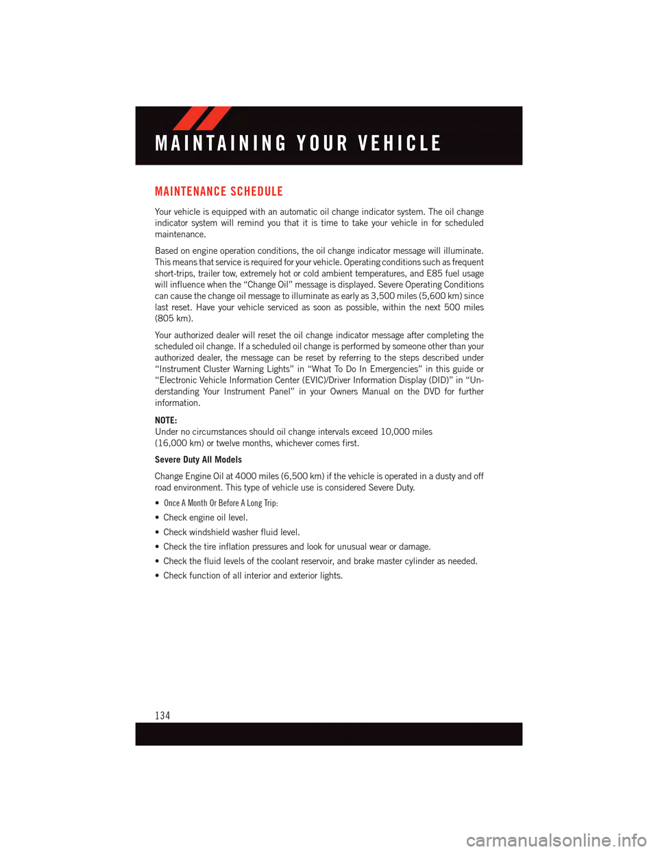
Yo u r v e h i c l e i s e q u i p p e d w i t h a n a u t o m a t i c o i l c h a n g e i n d i c a t o r s y s t e m . T h e o i l c h a n g e
indicator system will remind you that it is time to take your vehicle in for scheduled
maintenance.
Based on engine operation conditions, the oil change indicator message will illuminate.
This means that service is required for your vehicle. Operating conditions such as frequent
short-trips, trailer tow, extremely hot or cold ambient temperatures, and E85 fuel usage
will influence when the “Change Oil” message is displayed. Severe Operating Conditions
can cause the change oil message to illuminate as early as 3,500 miles (5,600 km) since
last reset. Have your vehicle serviced as soon as possible, within the next 500 miles
(805 km).
Yo u r a u t h o r i z e d d e a l e r w i l l r e s e t t h e o i l c h a n g e i n d i c a t o r m e s s a g e a f t e r c o m p l e t i n g t h e
scheduled oil change. If a scheduled oil change is performed by someone other than your
authorized dealer, the message can be reset by referring to the steps described under
“Instrument Cluster Warning Lights” in “What To Do In Emergencies” in this guide or
“Electronic Vehicle Information Center (EVIC)/Driver Information Display (DID)” in “Un-
derstanding Your Instrument Panel” in your Owners Manual on the DVD for further
information.
NOTE:
Under no circumstances should oil change intervals exceed 10,000 miles
(16,000 km) or twelve months, whichever comes first.
Severe Duty All Models
Change Engine Oil at 4000 miles (6,500 km) if the vehicle is operated in a dusty and off
road environment. This type of vehicle use is considered Severe Duty.
• Once A Month Or Before A Long Trip:
•Checkengineoillevel.
•Checkwindshieldwasherfluidlevel.
•Checkthetireinflationpressuresandlookforunusualwearordamage.
•Checkthefluidlevelsofthecoolantreservoir,andbrakemastercylinderasneeded.
•Checkfunctionofallinteriorandexteriorlights.
MAINTAINING YOUR VEHICLE
134
Page 142 of 164
Underhood Fuses
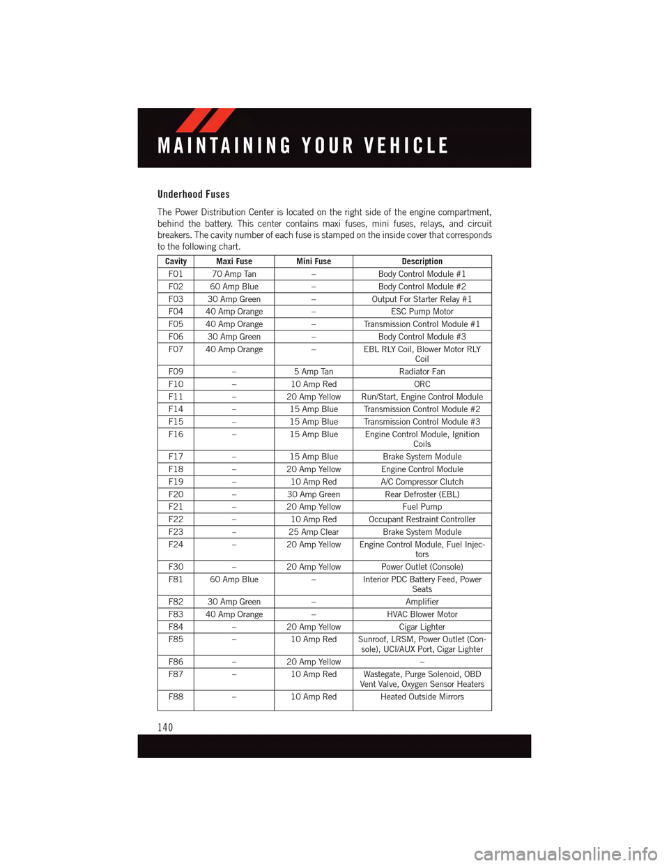
The Power Distribution Center is located on the right side of the engine compartment,
behind the battery. This center contains maxi fuses, mini fuses, relays, and circuit
breakers. The cavity number of each fuse is stamped on the inside cover that corresponds
to the following chart.
Cavity Maxi FuseMini FuseDescription
F01 70 Amp Tan–Body Control Module #1
F02 60 Amp Blue–Body Control Module #2
F03 30 Amp Green–Output For Starter Relay #1
F04 40 Amp Orange–ESC Pump Motor
F05 40 Amp Orange–Tr a n s m i s s i o n C o n t r o l M o d u l e # 1
F06 30 Amp Green–Body Control Module #3
F07 40 Amp Orange–EBL RLY Coil, Blower Motor RLYCoil
F09–5AmpTanRadiator Fan
F10–10 Amp RedORC
F11–20 Amp Yellow Run/Start, Engine Control Module
F14–15 Amp Blue Transmission Control Module #2
F15–15 Amp Blue Transmission Control Module #3
F16–15 Amp Blue Engine Control Module, IgnitionCoils
F17–15 Amp BlueBrake System Module
F18–20 Amp Yellow Engine Control Module
F19–10 Amp RedA/C Compressor Clutch
F20–30 Amp GreenRear Defroster (EBL)
F21–20 Amp YellowFuel Pump
F22–10 Amp Red Occupant Restraint Controller
F23–25 Amp ClearBrake System Module
F24–20 Amp Yellow Engine Control Module, Fuel Injec-tors
F30–20 Amp Yellow Power Outlet (Console)
F81 60 Amp Blue–Interior PDC Battery Feed, PowerSeats
F82 30 Amp Green–Amplifier
F83 40 Amp Orange–HVAC Blower Motor
F84–20 Amp YellowCigar Lighter
F85–10 Amp Red Sunroof, LRSM, Power Outlet (Con-sole), UCI/AUX Port, Cigar Lighter
F86–20 Amp Yellow–
F87–10 Amp Red Wastegate, Purge Solenoid, OBDVent Valve, Oxygen Sensor Heaters
F88–10 Amp Red Heated Outside Mirrors
MAINTAINING YOUR VEHICLE
140
Page 154 of 164
Adding Engine Coolant (Antifreeze) . .133
Adding Washer Fluid..........133
Air Bag
Advanced Front Air Bag.......16
Advance Front Air Bag.......16
Air Bags . . . . . . . . . . . . . . .16
Air Bag Warning Light . . . . . . . .16
Front Air Bag . . . . . . . . . . . .16
Rollover . . . . . . . . . . . . . . .16
Side Impacts.............16
Air bag Light . . . . . . . . . . . . . .104Air Cleaner, Engine (Engine Air CleanerFilter)................133Air Conditioner Maintenance.....133Air Conditioning Refrigerant......133Air Conditioning System........133AlarmVehicle Security Alarm.......13Alarm (Security Alarm)......13,106Antifreeze (Engine Coolant) . . .132, 133Capacities.............132Disposal . . . . . . . . . . . . . .133Anti-Lock Warning Light........103Appearance Care............133Assistance Towing...........100Audio Settings............53,56Audio Systems (Radio)..........5Automatic Headlights..........35Automatic TemperatureControl (ATC) . . . . . . . . . . .39, 41Automatic TransmissionFluid Type . . . . . . . . . . . . .133
Back-Up Camera............44Battery.................133Blind Spot Monitoring..........44Body Mechanism Lubrication.....133Brake Fluid . . . . . . . . . . . . . . .133Brakes . . . . . . . . . . . . . . . . .133Brake System.............133Master Cylinder..........133Warning Light . . . . . . . . . . .102Break-In Recommendations, NewVehicle . . . . . . . . . . . . . . . .32Bulb Replacement...........145Bulbs, Light . . . . . . . . . . . . . .145
Calibration, Compass..........90
Capacities, Antifreeze (Engine
Coolant)...............132
Capacities, Fluid............132
Caps, Filler
Oil (Engine)............133
Car Washes . . . . . . . . . . . . . . .133
Change Oil Indicator..........104
Changing A Flat Tire..........108
Charging System Light.........103
Child Restraint..............22
Child RestraintsChild Tether AnchorageLocations...............25CleaningWheels...............133Windshield Wiper Blades.....133Climate Control . . . . . . . . . . . . . .5Clock Setting...............53Cluster Warning/Indicator LightsAnti-Lock Brake (ABS) Light . . .103Brake Warning Light . . . . . . . .102Charging System Light......103Electronic Speed Control ONIndicator . . . . . . . . . . . . . .106Electronic Speed Control SETIndicator . . . . . . . . . . . . . .106Electronic Throttle Control (ETC) Indi-cator Light . . . . . . . . . . . . .104Engine Temperature WarningLight . . . . . . . . . . . . . . . .102Front Fog Light Indicator . . . . .106High Beam Indicator.......106
Malfunction Indicator Light (MIL)..103Oil Pressure Warning Light . . . .103Ti r e P r e s s u r e M o n i t o r i n g S y s t e m(TPMS) Light...........100Tu r n S i g n a l I n d i c a t o r.......106Vehicle Security Light.......106Clutch . . . . . . . . . . . . . . . . .133Clutch Fluid . . . . . . . . . . . . . .133Compact Spare Tire..........143Compass Calibration...........90Coolant (Antifreeze)..........132Cooling System . . . . . . . . . . . . .133Adding Coolant (Antifreeze)....133Coolant Level...........133Disposal of Used Coolant.....133Drain, Flush, and Refill......133
INDEX
152
Page 155 of 164
Inspection . . . . . . . . . . . . .133
Points to Remember.......133
Pressure Cap . . . . . . . . . . .133
Selection of Coolant (Antifreeze)..133
Corrosion Protection..........133
Cruise Light . . . . . . . . . . . . . . .36
Customer Assistance.......146, 147
Customer Programmable Features . . .94
Defects, Reporting...........148Dimmer Control.............35Dimmer Switch, Headlight.......35Disabled Vehicle Towing . . . . . . . .100DisposalAntifreeze (Engine Coolant)....133Door Locks.................8Driver Cockpit...............4
ElectronicsYo u r Ve h i c l e ' s S o u n dSystem.............50,51Electronic Stability Control (ESC) . . .100Electronic Stability Control (ESC) OFFIndicator . . . . . . . . . . . . . .103Electronic Throttle Control WarningLight . . . . . . . . . . . . . . . . .104Emergency, In Case ofFreeing Vehicle When Stuck . . .123Jacking . . . . . . . . . . . . . .108Overheating . . . . . . . . . . . .107To w i n g . . . . . . . . . . . . . . . 1 0 0EngineAir Cleaner.............133Break-In Recommendations....32Checking Oil Level.........133Cooling . . . . . . . . . . . . . . .133Oil . . . . . . . . . . . . . .132, 133Oil Filler Cap...........133Oil Selection . . . . . . . . .132, 133Overheating . . . . . . . . . . . .107Starting...............12Stopping..............12Te m p e r a t u r e W a r n i n g L i g h t....102Event Data Recorder..........124Exhaust System............133
FiltersAir Cleaner.............133
Engine Oil.............133
Engine Oil Disposal........133
Flashers
Tu r n S i g n a l............106
Flat Tire Changing...........108
Fluid, Brake . . . . . . . . . . . . . .133
Fluid Capacities............132
Fluids . . . . . . . . . . . . . . .132, 133
Fluids, Lubricants and Genuine
Parts . . . . . . . . . . . . . . . . .132Fog Lights . . . . . . . . . . . . .35, 106Folding Rear Seat............29Freeing A Stuck Vehicle . . . . . . . .123Front Heated Seats...........29FuelCapacity..............132Filler Cap (Gas Cap)........104Specifications...........132Ta n k C a p a c i t y...........132Fuse . . . . . . . . . . . . . . . . . .139Fuses . . . . . . . . . . . . . . . . . .139
Garage Door Opener (HomeLink®)...94Gasoline (Fuel).............132General Maintenance.........133Glass Cleaning.............133
HeadlightsAutomatic . . . . . . . . . . . . . .35Cleaning..............133Dimmer Switch...........35High Beam.............34Head Restraints.............26Heated Seats..............29Heated Steering Wheel.........30High Beam Indicator..........106High Beam/Low Beam Select (Dimmer)Switch . . . . . . . . . . . . . . . .34HomeLink®(Garage Door Opener) . . .94Hood Release.............125
Instrument Cluster............6Instrument Cluster Indicator Lights . .106Instrument Cluster Warning Lights . .100Instrument Panel Cover........133Instrument Panel Lens Cleaning . . .133Interior Appearance Care.......133Intermittent Wipers (Delay Wipers) . . .33
INDEX
153
Page 156 of 164
Introduction................2
iPod®/USB/MP3 Control
Bluetooth®Streaming Audio....72
Jacking Instructions . . . . . . . . . .109
Jack Location. . . . . . . . . . . . . .108
Jack Operation . . . . . . . . . . . . .109
Jump Starting.............120
Key Fob . . . . . . . . . . . . . . . . . .8
Lock The Doors............8Unlock The Doors...........8Keyless Enter-N-Go............9Lock/Unlock . . . . . . . . . . . . .10Starting/Stopping..........12Keyless Enter-N-Go™Lock The Vehicle’s Doors.......8
Lane Change Assist...........33Light Bulbs . . . . . . . . . . . . . . .145LightsFog . . . . . . . . . . . . . . . . .106High Beam Indicator . . . . . . .106Security Alarm...........106Ti r e P r e s s u r e M o n i t o r i n g ( T P M S )..100LocksDoor..................8Lower Anchors and Tether for CHildren(LATCH)................23Lubrication, Body...........133
Maintenance Free Battery . . . . . . .133Maintenance, General.........133Maintenance Procedures.......133Maintenance Record..........138Maintenance Schedule........134Malfunction Indicator Light (CheckEngine)...............103Manual Transmission..........46Master Cylinder (Brakes)........133MOPAR®Accessories.........149
Navigation Voice Commands......87New Vehicle Break-In Period . . . . . .32
Occupant Restraints........21,22Oil Change Indicator..........104Oil Change Indicator, Reset......104
Oil, Engine............132, 133
Capacity..............132
Change Interval..........133
Checking..............133
Disposal..............133
Filter................133
Filter Disposal...........133
Materials Added to........133
Recommendation......132, 133
Viscosity..............133
Oil Filter, Selection...........133Oil Pressure Light . . . . . . . . . . .103OutletPower................97Overheating, Engine..........107
Paint Care . . . . . . . . . . . . . . .133Panic Alarm................8Phone (Pairing)...........57,80Phone (Uconnect®). . . . . . . . .57,80Placard, Tire and LoadingInformation . . . . . . . . . . . . .142PowerGlass Sunroof............45Outlet (Auxiliary Electrical Outlet)..97Seats................27Preparation for Jacking........109
Rain Sensitive Wiper System......33Rear Camera...............44Rear Cross Path.............44Rear ParkSense System.........44Rear Seat, Folding............29Recreational Towing...........98Refrigerant . . . . . . . . . . . . . . .133Remote ControlTr u n k R e l e a s e . . . . . . . . . . . . 8Remote Keyless Entry (RKE)Lock The Doors............8Unlock The Doors...........8Remote Starting System.........9Replacement Bulbs..........145Reporting Safety Defects.......148Restraint, Head.............26Rocking Vehicle When Stuck.....123
Schedule, Maintenance........134Seat Belt Maintenance........133
INDEX
154